
 Product
 Brand
Brand Articles
 Tools
Tools
STM3240G-EVAL Complete Setup and Development Guide


EVAL BOARD FOR STM3240G
Set up your STM3240G-EVAL board with ease. Learn hardware connections, software installation, and run your first program to unlock its full potential.
Product Introduction
The STM3240G-EVAL is a powerful evaluation board designed to help you explore the capabilities of the STM32F4 series MCU. This board offers a good starting point for learning embedded systems and experimenting with hardware and software integration. With robust board support, it simplifies development and testing, making it ideal for beginners and professionals alike. Whether you are creating your first project or diving into advanced features, this eval board equips you with all the tools you need to succeed.
Unboxing and Hardware Setup
Components in the STM3240G-EVAL Package
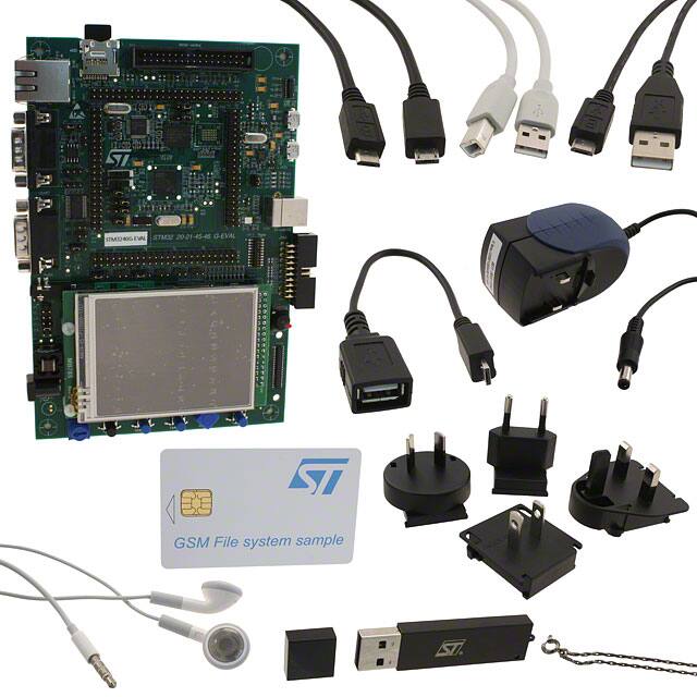
When you open the STM3240G-EVAL package, you will find everything you need to get started. The package includes the STM3240G evaluation board, a USB cable, and a power adapter. You will also receive a quick start guide to help you set up the board. Some packages may include additional accessories, such as an Ethernet cable or a touchscreen stylus, depending on the version you purchase.
Take a moment to inspect the contents. Ensure that all components are present and undamaged. If anything is missing, contact the seller immediately. Keeping the packaging intact can also be helpful for future storage or transportation.
Connecting Power and Peripherals to the STM3240G
To power the STM3240G, use the included power adapter. Locate the power input port on the board and securely connect the adapter. Plug the other end into a power outlet. You will notice an LED indicator light up, confirming that the board is receiving power.
Next, connect the USB cable to the board's USB port. This connection allows you to program the MCU and communicate with your computer. If your project requires additional peripherals, such as an Ethernet cable or external sensors, connect them to the appropriate ports on the board. Refer to the quick start guide for detailed port locations.
Ensuring Proper Hardware Connections
Before proceeding, double-check all connections. Ensure that the power adapter is firmly plugged in and the USB cable is securely attached. Verify that any additional peripherals are connected to the correct ports. Loose or incorrect connections can cause issues during operation.
If you encounter any problems, consult the quick start guide or the STM3240G-EVAL user manual. These resources provide diagrams and troubleshooting tips to help you resolve common issues. Taking the time to ensure proper connections will save you from potential headaches later.
Software Installation for STM3240G-EVAL
Downloading STM32CubeIDE and ST-LINK Drivers
To begin programming your STM3240G-EVAL, you need to install the necessary software. Start by downloading STM32CubeIDE, an integrated development environment (IDE) designed for STM32 microcontrollers. Visit the official STMicroelectronics website and navigate to the STM32CubeIDE download page. Select the version compatible with your operating system (Windows, macOS, or Linux).
You also need the ST-LINK drivers to enable communication between your computer and the STM3240G board. These drivers are available on the same website. Look for the ST-LINK Utility section and download the latest version.
Tip: If the download button is greyed, ensure you have created an account and logged in. Some downloads require user authentication.
Save both files to an easily accessible location on your computer. This will make the installation process smoother.
Installing and Configuring STM32CubeIDE for STM3240G
Once the downloads are complete, locate the STM32CubeIDE installer file. Double-click it to start the installation process. Follow the on-screen instructions to install the IDE. Choose the default settings unless you have specific preferences.
After installing the IDE, connect your STM3240G to your computer using the USB cable. Open STM32CubeIDE and navigate to the "Help" menu. Select "Install New Software" and ensure the ST-LINK drivers are properly installed. This step is crucial for establishing a connection with the STM3240G board.
Next, configure the IDE for your STM3240G-EVAL. Create a new workspace and select the STM32F4 series MCU as your target device. This ensures the IDE recognizes your board and provides the correct tools for development.
Note: If the download button is greyed during driver installation, check your internet connection and ensure no firewall settings are blocking the process.
Troubleshooting Software Installation Issues
Sometimes, you may encounter issues during installation. If the download button is greyed, verify that you are logged into the STMicroelectronics website. Clear your browser cache and try again.
If the IDE fails to recognize your STM3240G, double-check the USB connection. Ensure the cable is securely attached to both the board and your computer. Try using a different USB port if the problem persists.
For driver-related issues, open the Device Manager on your computer. Look for the ST-LINK device under "Universal Serial Bus controllers." If it appears with a yellow warning icon, reinstall the drivers.
Tip: Always restart your computer after installing new software or drivers. This helps resolve many common issues.
Once you resolve these problems, you can proceed to compile the project and upload it to your STM3240G-EVAL.
Running Your First Program on STM3240G

Creating a Simple Project in STM32CubeIDE
To get started, open STM32CubeIDE and create a new project. Select "File" from the menu and click "New STM32 Project." A device selector window will appear. Choose the STM32F4 series MCU that matches your STM3240G-EVAL board. This ensures the IDE generates the correct configuration files for your project.
Next, name your project and select the folder where you want to save it. The IDE will create a basic template with the necessary files. You can now add your code to the main.c file. For your first program, try a simple LED blink example. This is one of the easiest examples for this board and a great way to verify that everything is working.
Compiling, Uploading, and Running the Program
Once your code is ready, compile it by clicking the hammer icon in the toolbar. The IDE will check your code for errors and generate a binary file. If there are no errors, connect your STM3240G-EVAL to your computer using the USB cable.
To flash it to the board, click the green "Debug" button in the toolbar. The IDE will upload the binary file to the MCU and start the program. You should see the LED on the board blinking if you used the LED blink example. This confirms that the program has been successfully uploaded.
Verifying Program Execution on STM3240G-EVAL
After you flash it to the board, verify that the program is running as expected. Observe the board's behavior. If you used the LED blink example, check if the LED blinks at the correct interval. If the program doesn't work, use the debug feature in STM32CubeIDE. This tool helps you identify and fix issues in your code.
You can also explore other examples for this board to test different features. These examples provide a great way to learn more about the capabilities of your STM3240G-EVAL.
Exploring Advanced Features of STM3240G-EVAL
Using the Touchscreen Interface
The STM3240G-EVAL features a 3.2-inch TFT color LCD with a resolution of 240x320 pixels. This display includes a responsive touchscreen interface, enabling you to interact with your programs visually. Whether you are designing a graphical user interface (GUI) or testing touch-based applications, this feature provides a hands-on experience.
| Feature | Specification |
|---|---|
| Display | 3.2" 240x320 TFT color LCD |
| Touchscreen Interface | Yes |
| Microcontroller | STM32F417IGH6 |
To get started, use the STM32CubeIDE to create a project that utilizes the touchscreen. The IDE includes libraries and examples for touchscreen applications. For instance, you can design a simple button interface that changes the screen color when pressed. This is a great way to explore the touchscreen's capabilities while learning how to integrate hardware and software.
Networking with Ethernet on STM3240G
The STM3240G-EVAL supports Ethernet connectivity, making it ideal for network-based applications. With this feature, you can create projects that involve data transfer, remote monitoring, or IoT (Internet of Things) solutions. The board's Ethernet port allows you to connect it directly to a network, enabling communication with other devices or servers.
| Feature | Description |
|---|---|
| Ethernet | Enables network connectivity |
| CAN | Supports Controller Area Network communication |
To use Ethernet, connect a standard Ethernet cable to the board. Then, configure the network settings in your project using STM32CubeIDE. You can download example projects from the STMicroelectronics website to help you get started. These examples include basic client-server communication and data logging over a network. Experimenting with these projects will help you understand how to implement Ethernet-based solutions effectively.
Exploring Audio Capabilities
The STM3240G-EVAL includes advanced audio features, such as an integrated I2S audio DAC and a stereo audio jack. These features allow you to develop audio-based applications, such as music players or voice recorders. The I2S interface ensures high-quality audio output, making it suitable for professional-grade projects.
| Feature | Description |
|---|---|
| I2S audio DAC | Integrated digital-to-analog converter for audio |
| Stereo audio jack | Connector for headset audio output |
To explore the audio capabilities, start by downloading the audio example projects available in STM32CubeIDE. These projects demonstrate how to play audio files or generate sound using the board's DAC. You can also connect external speakers or headphones to the stereo jack for testing. This hands-on approach will help you understand how to integrate audio features into your applications.
Additional Resources for Advanced Applications
Unlocking the full potential of the STM3240G-EVAL board requires access to reliable resources. These tools and materials help you dive deeper into advanced applications, whether you're developing complex projects or exploring new features. Below are some curated resources to guide your journey:
Software development tools: Explore IDEs, debuggers, and utilities tailored for STM32 microcontrollers. These tools simplify programming and debugging tasks, ensuring smooth project execution.
Embedded software: Access libraries, BSP files, and firmware examples designed for STM32 boards. These resources provide ready-to-use code for various peripherals, saving you time during development.
Solutions: Discover application-specific solutions, including IoT frameworks and AI integration. These solutions demonstrate how to implement advanced features on the STM3240G-EVAL.
Developer resources: Find documentation, tutorials, and BSP files that help you understand the board's capabilities. These resources are essential for troubleshooting and optimizing your projects.
Case studies: Learn from real-world examples of STM32-based applications. These case studies showcase innovative uses of the board, inspiring you to create unique projects.
Tools: Access utilities for testing, monitoring, and optimizing your STM3240G-EVAL board. These tools enhance your workflow and ensure efficient development.
Community: Join forums and discussions to connect with other developers. The community offers valuable insights, tips, and solutions for common challenges.
Tip: Bookmark these resources for quick access during your development process. They provide essential support for both beginners and advanced users.
When working on advanced applications, BSP files play a crucial role. These files contain board-specific configurations, enabling seamless integration of hardware and software. For example, when implementing a touchscreen interface or Ethernet networking, BSP files ensure proper initialization and operation. Flash memory also becomes vital for storing firmware and application data. Efficient use of flash memory improves performance and reliability, especially in projects requiring frequent updates.
By leveraging these resources, you can confidently explore the STM3240G-EVAL's advanced features. Whether you're flashing new firmware or integrating BSP files into your project, these tools and examples will help you achieve your goals.
The STM3240G-EVAL board offers a seamless path from setup to advanced development. You’ve learned how to unbox, connect hardware, install software, and run your first program. Its versatility shines in applications like ROS 2 prototypes, where performance currently reaches 3 Hz but promises future improvements. Experiment with its touchscreen, Ethernet, and audio features to unlock its full potential. Each project you create builds your skills and opens new possibilities. Keep exploring, and let this board inspire your next innovation.
FAQ
What should I do if my STM3240G-EVAL board doesn’t power on?
Check the power adapter connection. Ensure the adapter is plugged into a working outlet and securely connected to the board. Verify the LED indicator on the board. If it remains off, inspect the adapter for damage or replace it.
Can I use STM3240G-EVAL with operating systems other than Windows?
Yes, STM32CubeIDE supports macOS and Linux. Download the compatible version from the STMicroelectronics website. Ensure you install the correct ST-LINK drivers for your operating system to establish communication with the board.
How do I debug a program that isn’t running correctly?
Use the debug feature in STM32CubeIDE. Connect the board via USB and click the "Debug" button. Monitor the IDE for error messages or unexpected behavior. Adjust your code based on the debug output to resolve issues.
Is the touchscreen interface difficult to program?
No, STM32CubeIDE provides libraries and examples for touchscreen applications. Start with simple projects, like creating a button interface. These examples guide you through the process, making it easy to integrate touchscreen functionality into your programs.
Where can I find additional resources for STM3240G-EVAL?
Visit the STMicroelectronics website for documentation, tutorials, and example projects. Explore the community forums for tips and solutions. Bookmark these resources to access them quickly during development.
Specifications
- TypeParameter
- Mounting Type
The "Mounting Type" in electronic components refers to the method used to attach or connect a component to a circuit board or other substrate, such as through-hole, surface-mount, or panel mount.
Fixed - Series
In electronic components, the "Series" refers to a group of products that share similar characteristics, designs, or functionalities, often produced by the same manufacturer. These components within a series typically have common specifications but may vary in terms of voltage, power, or packaging to meet different application needs. The series name helps identify and differentiate between various product lines within a manufacturer's catalog.
STM32F4 - Part Status
Parts can have many statuses as they progress through the configuration, analysis, review, and approval stages.
Active - Moisture Sensitivity Level (MSL)
Moisture Sensitivity Level (MSL) is a standardized rating that indicates the susceptibility of electronic components, particularly semiconductors, to moisture-induced damage during storage and the soldering process, defining the allowable exposure time to ambient conditions before they require special handling or baking to prevent failures
1 (Unlimited) - TypeMCU 32-Bit
- Operating Supply Voltage
The voltage level by which an electrical system is designated and to which certain operating characteristics of the system are related.
5V - Interface
In electronic components, the term "Interface" refers to the point at which two different systems, devices, or components connect and interact with each other. It can involve physical connections such as ports, connectors, or cables, as well as communication protocols and standards that facilitate the exchange of data or signals between the connected entities. The interface serves as a bridge that enables seamless communication and interoperability between different parts of a system or between different systems altogether. Designing a reliable and efficient interface is crucial in ensuring proper functionality and performance of electronic components and systems.
CAN, Ethernet, I2C, RS-232, SPI, USB - Number of Bits32
- Core Processor
The term "Core Processor" typically refers to the central processing unit (CPU) of a computer or electronic device. It is the primary component responsible for executing instructions, performing calculations, and managing data within the system. The core processor is often considered the brain of the device, as it controls the overall operation and functionality. It is crucial for determining the speed and performance capabilities of the device, as well as its ability to handle various tasks and applications efficiently. In modern devices, core processors can have multiple cores, allowing for parallel processing and improved multitasking capabilities.
ARM® Cortex®-M4 - Data Bus Width
The data bus width in electronic components refers to the number of bits that can be transferred simultaneously between the processor and memory. It determines the amount of data that can be processed and transferred in a single operation. A wider data bus allows for faster data transfer speeds and improved overall performance of the electronic device. Common data bus widths include 8-bit, 16-bit, 32-bit, and 64-bit, with higher numbers indicating a larger capacity for data transfer. The data bus width is an important specification to consider when evaluating the speed and efficiency of a computer system or other electronic device.
32b - Utilized IC / Part
Utilized IC / Part is a parameter that refers to the extent to which an integrated circuit (IC) or electronic component is being used or consumed within a system or application. It typically indicates the percentage or ratio of the component's capabilities that are being utilized in a given scenario. This parameter is important for assessing the efficiency and performance of the component, as well as for determining if the component is being underutilized or overburdened in a particular application. Monitoring and optimizing the utilization of ICs and electronic parts can help improve overall system reliability, efficiency, and cost-effectiveness.
STM32F407IGH6 - Evaluation Kit
An Evaluation Kit is a collection of hardware and software components designed to help engineers and developers assess and test the functionality of a particular electronic component or system. It typically includes a development board, sample code, utilities, and documentation to facilitate development and prototype testing. Evaluation Kits enable users to quickly prototype applications, evaluate performance characteristics, and determine compatibility with other systems. They are commonly used in the design and development phases of electronic projects to simplify the integration of complex components.
Yes - Core Architecture
In electronic components, the term "Core Architecture" refers to the fundamental design and structure of the component's internal circuitry. It encompasses the arrangement of key components, such as processors, memory units, and input/output interfaces, within the device. The core architecture plays a crucial role in determining the component's performance, power efficiency, and overall capabilities. Different core architectures are optimized for specific applications and requirements, such as high-speed processing, low power consumption, or specialized functions. Understanding the core architecture of electronic components is essential for engineers and designers to select the most suitable components for their projects.
ARM - ContentsBoard(s), Cable(s), LCD, Power Supply, Accessories
- Board Type
Board Type refers to the specific configuration or category of a printed circuit board (PCB) used in electronic devices. It defines the characteristics and design of the board, such as single-sided, double-sided, or multilayer constructions. The Board Type impacts factors like signal integrity, power distribution, and thermal management, influencing the overall performance and functionality of the electronic component. Different applications and environments may require specific Board Types to meet durability and operational requirements.
Evaluation Platform - REACH SVHC
The parameter "REACH SVHC" in electronic components refers to the compliance with the Registration, Evaluation, Authorization, and Restriction of Chemicals (REACH) regulation regarding Substances of Very High Concern (SVHC). SVHCs are substances that may have serious effects on human health or the environment, and their use is regulated under REACH to ensure their safe handling and minimize their impact.Manufacturers of electronic components need to declare if their products contain any SVHCs above a certain threshold concentration and provide information on the safe use of these substances. This information allows customers to make informed decisions about the potential risks associated with using the components and take appropriate measures to mitigate any hazards.Ensuring compliance with REACH SVHC requirements is essential for electronics manufacturers to meet regulatory standards, protect human health and the environment, and maintain transparency in their supply chain. It also demonstrates a commitment to sustainability and responsible manufacturing practices in the electronics industry.
No SVHC - Radiation Hardening
Radiation hardening is the process of making electronic components and circuits resistant to damage or malfunction caused by high levels of ionizing radiation, especially for environments in outer space (especially beyond the low Earth orbit), around nuclear reactors and particle accelerators, or during nuclear accidents or nuclear warfare.
No - RoHS Status
RoHS means “Restriction of Certain Hazardous Substances” in the “Hazardous Substances Directive” in electrical and electronic equipment.
ROHS3 Compliant - Lead Free
Lead Free is a term used to describe electronic components that do not contain lead as part of their composition. Lead is a toxic material that can have harmful effects on human health and the environment, so the electronics industry has been moving towards lead-free components to reduce these risks. Lead-free components are typically made using alternative materials such as silver, copper, and tin. Manufacturers must comply with regulations such as the Restriction of Hazardous Substances (RoHS) directive to ensure that their products are lead-free and environmentally friendly.
Lead Free
Parts with Similar Specs
- ImagePart NumberManufacturerData Bus WidthInterfaceLead FreeNumber of BitsPart StatusRadiation HardeningREACH SVHCRoHS StatusView Compare
![STM3240G-EVAL]()
STM3240G-EVAL
32 b
CAN, Ethernet, I2C, RS-232, SPI, USB
Lead Free
32
Active
No
No SVHC
ROHS3 Compliant
![PIC32MX575F256L-80I/PT]()
32 b
CAN, I2C, SPI, UART, USART, USB
Lead Free
32
Active
No
No SVHC
ROHS3 Compliant
![PIC32MX795F512L-80I/PT]()
32 b
CAN, Ethernet, I2C, SPI, UART, USART, USB
Lead Free
32
Active
No
No SVHC
ROHS3 Compliant
![PIC32MX795F512H-80I/PT]()
32 b
CAN, Ethernet, I2C, SPI, UART, USART, USB
Lead Free
32
Active
No
No SVHC
ROHS3 Compliant


Datasheet PDF
- Datasheets :
 XC2S200-5PQG208C and XC2S200-5PQ208C A Detailed Comparison
06 June 2025210
 ATMEGA328P-MU AVR 8-bit Microcontrollers - MCU 32KB In-system: Datasheet, Pinout, and Equivalents
24 February 20223730
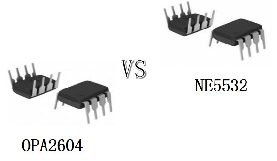 OPA2604 VS NE5532 How to differentiate them?
14 April 202213120
 MCP25625 CAN Controller: Datasheet, Block Diagram, Feature
06 October 20213602
 ATmega16 Microcontroller: Datasheet, Pinout and Alternatives
16 July 202110738
 Kintex-7 Series Technical Guide: Selection, Design, Alternatives
14 January 20261806
 Microchip PIC16F1613TIML Microcontroller Datasheet Overview
29 February 2024133
 74HC193 Counter: Specification, Pinout and Datasheet PDF
21 June 20217751
 An Overview of LPDDR
25 March 202637137
 A Guide to Selecting the Ideal Microphone for Your Audio Needs
15 May 20232147
 Introduction to Mass Air Flow Sensor
15 September 202010799
 Transceivers Shortage Outlook 2026: Supply, Lead Times, and Sourcing Options
09 July 2026364
 Comparing Heat Sink Types for Modern Applications
19 July 20253647
 Selection and Optimization of Peripheral Components for DC-DC Boost Regulator
15 April 20222249
 An Introduction to DIACs
21 May 20256282
 Nexperia Chip Alternative Selection Guide: Cross-Reference Compatible Models & Parameter Comparison
21 October 20258775
STMicroelectronics
In Stock: 2365
United States
China
Canada
Japan
Russia
Germany
United Kingdom
Singapore
Italy
Hong Kong(China)
Taiwan(China)
France
Korea
Mexico
Netherlands
Malaysia
Austria
Spain
Switzerland
Poland
Thailand
Vietnam
India
United Arab Emirates
Afghanistan
Åland Islands
Albania
Algeria
American Samoa
Andorra
Angola
Anguilla
Antigua & Barbuda
Argentina
Armenia
Aruba
Australia
Azerbaijan
Bahamas
Bahrain
Bangladesh
Barbados
Belarus
Belgium
Belize
Benin
Bermuda
Bhutan
Bolivia
Bonaire, Sint Eustatius and Saba
Bosnia & Herzegovina
Botswana
Brazil
British Indian Ocean Territory
British Virgin Islands
Brunei
Bulgaria
Burkina Faso
Burundi
Cabo Verde
Cambodia
Cameroon
Cayman Islands
Central African Republic
Chad
Chile
Christmas Island
Cocos (Keeling) Islands
Colombia
Comoros
Congo
Congo (DRC)
Cook Islands
Costa Rica
Côte d’Ivoire
Croatia
Cuba
Curaçao
Cyprus
Czechia
Denmark
Djibouti
Dominica
Dominican Republic
Ecuador
Egypt
El Salvador
Equatorial Guinea
Eritrea
Estonia
Eswatini
Ethiopia
Falkland Islands
Faroe Islands
Fiji
Finland
French Guiana
French Polynesia
Gabon
Gambia
Georgia
Ghana
Gibraltar
Greece
Greenland
Grenada
Guadeloupe
Guam
Guatemala
Guernsey
Guinea
Guinea-Bissau
Guyana
Haiti
Honduras
Hungary
Iceland
Indonesia
Iran
Iraq
Ireland
Isle of Man
Israel
Jamaica
Jersey
Jordan
Kazakhstan
Kenya
Kiribati
Kosovo
Kuwait
Kyrgyzstan
Laos
Latvia
Lebanon
Lesotho
Liberia
Libya
Liechtenstein
Lithuania
Luxembourg
Macao(China)
Madagascar
Malawi
Maldives
Mali
Malta
Marshall Islands
Martinique
Mauritania
Mauritius
Mayotte
Micronesia
Moldova
Monaco
Mongolia
Montenegro
Montserrat
Morocco
Mozambique
Myanmar
Namibia
Nauru
Nepal
New Caledonia
New Zealand
Nicaragua
Niger
Nigeria
Niue
Norfolk Island
North Korea
North Macedonia
Northern Mariana Islands
Norway
Oman
Pakistan
Palau
Palestinian Authority
Panama
Papua New Guinea
Paraguay
Peru
Philippines
Pitcairn Islands
Portugal
Puerto Rico
Qatar
Réunion
Romania
Rwanda
Samoa
San Marino
São Tomé & Príncipe
Saudi Arabia
Senegal
Serbia
Seychelles
Sierra Leone
Sint Maarten
Slovakia
Slovenia
Solomon Islands
Somalia
South Africa
South Sudan
Sri Lanka
St Helena, Ascension, Tristan da Cunha
St. Barthélemy
St. Kitts & Nevis
St. Lucia
St. Martin
St. Pierre & Miquelon
St. Vincent & Grenadines
Sudan
Suriname
Svalbard & Jan Mayen
Sweden
Syria
Tajikistan
Tanzania
Timor-Leste
Togo
Tokelau
Tonga
Trinidad & Tobago
Tunisia
Turkey
Turkmenistan
Turks & Caicos Islands
Tuvalu
U.S. Outlying Islands
U.S. Virgin Islands
Uganda
Ukraine
Uruguay
Uzbekistan
Vanuatu
Vatican City
Venezuela
Wallis & Futuna
Yemen
Zambia
Zimbabwe
![NUCLEO-F030R8]() NUCLEO-F030R8
NUCLEO-F030R8STMicroelectronics
![SPC560B-DIS]() SPC560B-DIS
SPC560B-DISSTMicroelectronics
![NUCLEO-L152RE]() NUCLEO-L152RE
NUCLEO-L152RESTMicroelectronics
![NUCLEO-F411RE]() NUCLEO-F411RE
NUCLEO-F411RESTMicroelectronics
![NUCLEO-F767ZI]() NUCLEO-F767ZI
NUCLEO-F767ZISTMicroelectronics
![NUCLEO-F401RE]() NUCLEO-F401RE
NUCLEO-F401RESTMicroelectronics
![NUCLEO-F412ZG]() NUCLEO-F412ZG
NUCLEO-F412ZGSTMicroelectronics
![STM32F769I-DISCO]() STM32F769I-DISCO
STM32F769I-DISCOSTMicroelectronics
![NUCLEO-F429ZI]() NUCLEO-F429ZI
NUCLEO-F429ZISTMicroelectronics
![STM32F746G-DISCO]() STM32F746G-DISCO
STM32F746G-DISCOSTMicroelectronics


