SI4133 Integrated Circuit: Pinout, Features and Datasheet
3V Frequency Synthesizer SI4133 Clock Generators 28 Pins 28-VFQFN Exposed Pad 28 Terminals Surface Mount 2.7V~3.6V Tray
Unit Price: $5.722840
Ext Price: $5.72


3V Frequency Synthesizer SI4133 Clock Generators 28 Pins 28-VFQFN Exposed Pad 28 Terminals Surface Mount 2.7V~3.6V Tray
The SI4133 is a monolithic integrated circuit that performs both IF and dualband RF synthesis for wireless communications applications. The SI4133 includes three VCOs, loop filters, reference and VCO dividers, and phase detectors. Divider and powerdown settings are programmable with a threewire serial interface. Furthermore, Huge range of Semiconductors, Capacitors, Resistors and IcS in stock. Welcome RFQ.

What Is An Integrated Circuit (IC)
SI4133 Pinout
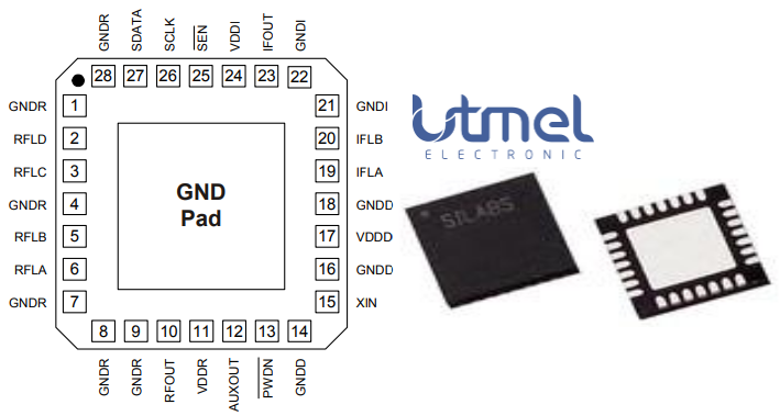
Pinout
SI4133 CAD Model
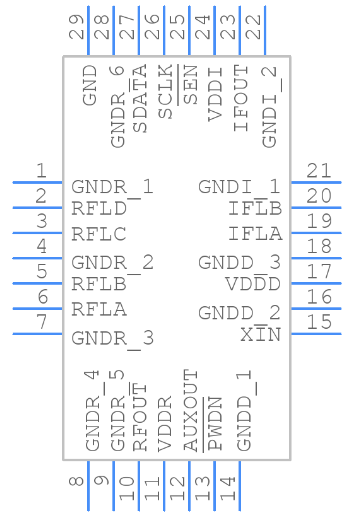
PCB Symbol
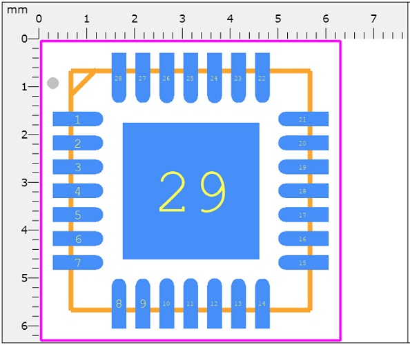
PCB Footprint
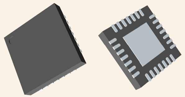
3D Model
SI4133 Overview
The SI4133 is a monolithic integrated circuit that performs IF and dual-band RF synthesis for wireless communications applications. This integrated circuit (IC), with minimal external components, completes the frequency synthesis function necessary for RF communications systems. The SI4133 has three complete phase-locked loops (PLLs) with integrated voltage-controlled oscillators (VCOs). The low phase noise of the VCOs makes the SI4133 suitable for demanding wireless communications applications. The SI4133 is programmed serially with 22-bit words comprised of 18-bit data fields and 4-bit address fields. The SI4133 may operate at an extended frequency range of 1850 MHz to 2050 MHz by connecting the RFLA and RFLB pins directly.
This article provides you with a basic overview of the SI4133 Integrated Circuit, including its pin descriptions, features and specifications, etc., to help you quickly understand what SI4133 is.
SI4133 Features
● Dual-band RF synthesizers
◆ RF1: 900 MHz to 1.8 GHz
◆ RF2: 750 MHz to 1.5 GHz
● IF synthesizer: 62.5 to 1000 MHz
● Integrated VCOs, loop filters, varactors, and resonators
● Minimal (2) number of external components required
● Low phase noise
● Programmable powerdown modes
● 1 µA standby current
● 18 mA typical supply current
● 2.7 to 3.6 V operation
● Packages: 24-pin TSSOP, 28-lead QFN
◆ Lead-free and RoHS compliant
Specifications
- TypeParameter
- Factory Lead Time8 Weeks
- Mounting Type
The "Mounting Type" in electronic components refers to the method used to attach or connect a component to a circuit board or other substrate, such as through-hole, surface-mount, or panel mount.
Surface Mount - Package / Case
refers to the protective housing that encases an electronic component, providing mechanical support, electrical connections, and thermal management.
28-VFQFN Exposed Pad - Surface Mount
having leads that are designed to be soldered on the side of a circuit board that the body of the component is mounted on.
YES - Number of Pins28
- Weight63.58798mg
- Frequency(Max)1.8GHz
- Number of Elements3
- Operating Temperature
The operating temperature is the range of ambient temperature within which a power supply, or any other electrical equipment, operate in. This ranges from a minimum operating temperature, to a peak or maximum operating temperature, outside which, the power supply may fail.
-40°C~85°C - Packaging
Semiconductor package is a carrier / shell used to contain and cover one or more semiconductor components or integrated circuits. The material of the shell can be metal, plastic, glass or ceramic.
Tray - Published2017
- JESD-609 Code
The "JESD-609 Code" in electronic components refers to a standardized marking code that indicates the lead-free solder composition and finish of electronic components for compliance with environmental regulations.
e3 - Pbfree Code
The "Pbfree Code" parameter in electronic components refers to the code or marking used to indicate that the component is lead-free. Lead (Pb) is a toxic substance that has been widely used in electronic components for many years, but due to environmental concerns, there has been a shift towards lead-free alternatives. The Pbfree Code helps manufacturers and users easily identify components that do not contain lead, ensuring compliance with regulations and promoting environmentally friendly practices. It is important to pay attention to the Pbfree Code when selecting electronic components to ensure they meet the necessary requirements for lead-free applications.
yes - Part Status
Parts can have many statuses as they progress through the configuration, analysis, review, and approval stages.
Active - Moisture Sensitivity Level (MSL)
Moisture Sensitivity Level (MSL) is a standardized rating that indicates the susceptibility of electronic components, particularly semiconductors, to moisture-induced damage during storage and the soldering process, defining the allowable exposure time to ambient conditions before they require special handling or baking to prevent failures
3 (168 Hours) - Number of Terminations28
- TypeFrequency Synthesizer
- Terminal Finish
Terminal Finish refers to the surface treatment applied to the terminals or leads of electronic components to enhance their performance and longevity. It can improve solderability, corrosion resistance, and overall reliability of the connection in electronic assemblies. Common finishes include nickel, gold, and tin, each possessing distinct properties suitable for various applications. The choice of terminal finish can significantly impact the durability and effectiveness of electronic devices.
Matte Tin (Sn) - Voltage - Supply
Voltage - Supply refers to the range of voltage levels that an electronic component or circuit is designed to operate with. It indicates the minimum and maximum supply voltage that can be applied for the device to function properly. Providing supply voltages outside this range can lead to malfunction, damage, or reduced performance. This parameter is critical for ensuring compatibility between different components in a circuit.
2.7V~3.6V - Terminal Position
In electronic components, the term "Terminal Position" refers to the physical location of the connection points on the component where external electrical connections can be made. These connection points, known as terminals, are typically used to attach wires, leads, or other components to the main body of the electronic component. The terminal position is important for ensuring proper connectivity and functionality of the component within a circuit. It is often specified in technical datasheets or component specifications to help designers and engineers understand how to properly integrate the component into their circuit designs.
QUAD - Peak Reflow Temperature (Cel)
Peak Reflow Temperature (Cel) is a parameter that specifies the maximum temperature at which an electronic component can be exposed during the reflow soldering process. Reflow soldering is a common method used to attach electronic components to a circuit board. The Peak Reflow Temperature is crucial because it ensures that the component is not damaged or degraded during the soldering process. Exceeding the specified Peak Reflow Temperature can lead to issues such as component failure, reduced performance, or even permanent damage to the component. It is important for manufacturers and assemblers to adhere to the recommended Peak Reflow Temperature to ensure the reliability and functionality of the electronic components.
260 - Number of Functions1
- Supply Voltage
Supply voltage refers to the electrical potential difference provided to an electronic component or circuit. It is crucial for the proper operation of devices, as it powers their functions and determines performance characteristics. The supply voltage must be within specified limits to ensure reliability and prevent damage to components. Different electronic devices have specific supply voltage requirements, which can vary widely depending on their design and intended application.
3V - Terminal Pitch
The center distance from one pole to the next.
0.5mm - Frequency
In electronic components, the parameter "Frequency" refers to the rate at which a signal oscillates or cycles within a given period of time. It is typically measured in Hertz (Hz) and represents how many times a signal completes a full cycle in one second. Frequency is a crucial aspect in electronic components as it determines the behavior and performance of various devices such as oscillators, filters, and communication systems. Understanding the frequency characteristics of components is essential for designing and analyzing electronic circuits to ensure proper functionality and compatibility with other components in a system.
26MHz - Time@Peak Reflow Temperature-Max (s)
Time@Peak Reflow Temperature-Max (s) refers to the maximum duration that an electronic component can be exposed to the peak reflow temperature during the soldering process, which is crucial for ensuring reliable solder joint formation without damaging the component.
40 - Base Part Number
The "Base Part Number" (BPN) in electronic components serves a similar purpose to the "Base Product Number." It refers to the primary identifier for a component that captures the essential characteristics shared by a group of similar components. The BPN provides a fundamental way to reference a family or series of components without specifying all the variations and specific details.
SI4133 - Output
In electronic components, the parameter "Output" typically refers to the signal or data that is produced by the component and sent to another part of the circuit or system. The output can be in the form of voltage, current, frequency, or any other measurable quantity depending on the specific component. The output of a component is often crucial in determining its functionality and how it interacts with other components in the circuit. Understanding the output characteristics of electronic components is essential for designing and troubleshooting electronic circuits effectively.
Clock - Pin Count
a count of all of the component leads (or pins)
28 - Operating Supply Voltage
The voltage level by which an electrical system is designated and to which certain operating characteristics of the system are related.
3V - Supply Voltage-Min (Vsup)
The parameter "Supply Voltage-Min (Vsup)" in electronic components refers to the minimum voltage level required for the component to operate within its specified performance range. This parameter indicates the lowest voltage that can be safely applied to the component without risking damage or malfunction. It is crucial to ensure that the supply voltage provided to the component meets or exceeds this minimum value to ensure proper functionality and reliability. Failure to adhere to the specified minimum supply voltage may result in erratic behavior, reduced performance, or even permanent damage to the component.
2.7V - Number of Circuits1
- Nominal Supply Current
Nominal current is the same as the rated current. It is the current drawn by the motor while delivering rated mechanical output at its shaft.
27mA - Input
In electronic components, "Input" refers to the signal or data that is provided to a device or system for processing or manipulation. It is the information or command that is received by the component to initiate a specific function or operation. The input can come from various sources such as sensors, other electronic devices, or user interactions. It is crucial for the proper functioning of the component as it determines how the device will respond or behave based on the input received. Understanding and managing the input parameters is essential in designing and using electronic components effectively.
Crystal - Ratio - Input:Output
The parameter "Ratio - Input:Output" in electronic components refers to the relationship between the input and output quantities of a device or system. It is a measure of how the input signal or energy is transformed or converted into the output signal or energy. This ratio is often expressed as a numerical value or percentage, indicating the efficiency or effectiveness of the component in converting the input to the desired output. A higher ratio typically signifies better performance or higher efficiency, while a lower ratio may indicate losses or inefficiencies in the conversion process. Understanding and optimizing the input-output ratio is crucial in designing and evaluating electronic components for various applications.
1:3 - PLL
PLL stands for Phase-Locked Loop, which is a control system that generates an output signal whose phase is related to the phase of an input signal. It is commonly used in electronic components to synchronize, modulate, demodulate, filter, or recover a signal's frequency. A PLL typically consists of a phase detector, a loop filter, a voltage-controlled oscillator (VCO), and a feedback circuit. The PLL locks the phase of the output signal to the phase of the input signal, making it a versatile tool in various applications such as frequency synthesis, clock recovery, and frequency modulation.
Yes - Differential - Input:Output
Differential - Input:Output refers to the relationship between the input and output signals in differential amplifiers or circuits. It measures the difference in voltage between two input terminals and produces an output that is proportional to this difference. This parameter is essential for noise rejection and improving signal integrity in various applications, such as operational amplifiers and data acquisition systems. It allows circuits to effectively amplify small signals while minimizing interference and common-mode noise.
No/No - Divider/Multiplier
The parameter "Divider/Multiplier" in electronic components refers to a feature that allows the component to divide or multiply an input signal by a certain factor. This feature is commonly found in components such as operational amplifiers, voltage regulators, and signal processing circuits. In the context of operational amplifiers, the Divider/Multiplier parameter indicates the ability of the amplifier to scale the input signal by a specific factor, either dividing it or multiplying it. This can be useful for adjusting the amplitude or gain of a signal in a circuit.Overall, the Divider/Multiplier parameter provides flexibility in signal processing applications by allowing users to manipulate the input signal according to their specific requirements, whether it involves scaling down the signal for further processing or amplifying it for increased output.
Yes/No - Length5mm
- Height Seated (Max)
Height Seated (Max) is a parameter in electronic components that refers to the maximum allowable height of the component when it is properly seated or installed on a circuit board or within an enclosure. This specification is crucial for ensuring proper fit and alignment within the overall system design. Exceeding the maximum seated height can lead to mechanical interference, electrical shorts, or other issues that may impact the performance and reliability of the electronic device. Manufacturers provide this information to help designers and engineers select components that will fit within the designated space and function correctly in the intended application.
0.9mm - Width5mm
- Radiation Hardening
Radiation hardening is the process of making electronic components and circuits resistant to damage or malfunction caused by high levels of ionizing radiation, especially for environments in outer space (especially beyond the low Earth orbit), around nuclear reactors and particle accelerators, or during nuclear accidents or nuclear warfare.
No - RoHS Status
RoHS means “Restriction of Certain Hazardous Substances” in the “Hazardous Substances Directive” in electrical and electronic equipment.
RoHS Compliant - Lead Free
Lead Free is a term used to describe electronic components that do not contain lead as part of their composition. Lead is a toxic material that can have harmful effects on human health and the environment, so the electronics industry has been moving towards lead-free components to reduce these risks. Lead-free components are typically made using alternative materials such as silver, copper, and tin. Manufacturers must comply with regulations such as the Restriction of Hazardous Substances (RoHS) directive to ensure that their products are lead-free and environmentally friendly.
Lead Free
SI4133 Functional Block Diagram
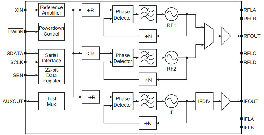
Functional Block Diagram
Parts with Similar Specs
- ImagePart NumberManufacturerPackage / CaseNumber of PinsPLLInputFrequency (Max)Supply VoltageTerminal PitchPbfree CodeView Compare
SI4133-D-GM
28-VFQFN Exposed Pad
28
Yes
Crystal
1.8GHz
3 V
0.5 mm
yes
24-VFQFN Exposed Pad
24
Yes
LVCMOS, Crystal
106.25MHz
3.3 V
0.5 mm
yes
28-VFQFN Exposed Pad
28
Yes
Crystal
1.8GHz
3 V
0.5 mm
yes
28-VFQFN Exposed Pad
28
Yes
Crystal
1.8GHz
3 V
0.5 mm
yes
28-VFQFN Exposed Pad
28
Yes
Crystal
1.5GHz
3 V
0.5 mm
yes
SI4133 Applications
● Dual-band communications
● Digital cellular telephones GSM 850, E-GSM 900, DCS 1800, PCS 1900
● Digital cordless phones
● Analog cordless phones
● Wireless local loop
SI4133 Package
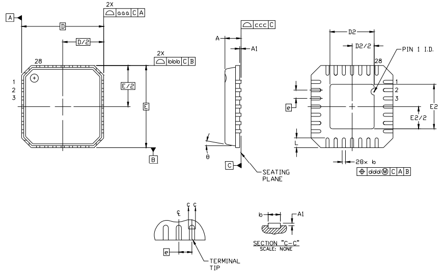
Package Outline
SI4133 Manufacturer
Silicon Labs (NASDAQ: SLAB) is a leading provider of silicon, software and system solutions for the Internet of Things, Internet infrastructure, industrial control, consumer and automotive markets. Resolving the electronics industry's toughest problems, providing customers with significant advantages in performance, energy savings, connectivity, and design simplicity. Backed by world-class engineering teams with unsurpassed software and mixed-signal design expertise, Silicon Labs empowers developers with the tools and technologies they need to advance quickly and easily from initial idea to final product.
Trend Analysis
Datasheet PDF
- Datasheets :
What is the essential property of the SI4133?
The SI4133 is a monolithic integrated circuit that performs both IF and dualband RF synthesis for wireless communications applications. The SI4133 includes three VCOs, loop filters, reference and VCO dividers, and phase detectors.
Is SI4133 suitable for demanding wireless communication applications?
The SI4133 has three complete phase-locked loops (PLLs) with integrated voltage-controlled oscillators (VCOs). The low phase noise of the VCOs makes the SI4133 suitable for demanding wireless communications applications.
What is the extended frequency range of SI4133?
The SI4133 may operate at an extended frequency range of 1850 MHz to 2050 MHz by connecting the RFLA and RFLB pins directly.
 Texas Instruments MSP430F15x/F16x/F161x Mixed Signal Microcontroller: A Comprehensive Overview
29 February 202499
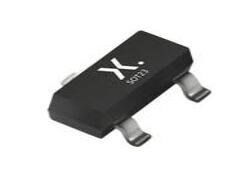 PMBT2222A Transistor: PMBT2222A, SOT23, Datasheet
28 April 20222046
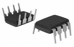 MCP2551 Transceiver: Circuits, Pinout, and Datasheet
22 December 20219734
 L5973D:35V, 250kHz, Pinout and Datasheet
07 March 20221329
 AP7331 Linear Regulator: Features, Pinout and Datasheet
11 March 2022686
 PCA9555 CMOS Device: Datasheet, Pinout, Application Circuit
21 October 20214168
 AR8031 Ethernet Transceiver: Features, Equivalent and Datasheet
19 January 20223625
 TL431CZ Automotive Adjustable Voltage Reference: Pinout, Datasheet, and Applications
16 September 2021552
 What is a Memory Controller?
12 August 202031838
 The Development Trends in the Field of Electronic Component Applications
28 July 20233255
 Lattice FPGA: The Ultimate Guide to Low-Power, Small Form Factor Solutions
19 September 20251801
 What is PWM "Dead Band"?
21 April 20226317
 Things You Need to Know about Seven-segment Display
14 October 20216580
 Global Semiconductor Industry Outlook: SEMI Discusses the Future
06 September 20231715
 What is Comparator?
11 April 20225676
 Electronic Components in the Smart Home System
24 April 20251041
Silicon Labs
In Stock
Minimum: 1 Multiples: 1
Qty
Unit Price
Ext Price
1
$5.722840
$5.72
10
$5.398906
$53.99
100
$5.093308
$509.33
500
$4.805007
$2,402.50
1000
$4.533026
$4,533.03
Not the price you want? Send RFQ Now and we'll contact you ASAP.
Inquire for More Quantity


