
 Product
 Brand
Brand Articles
 Tools
Tools
IL511 Digital Isolators: Datasheet, Pinout and Applications


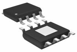
DGTL ISO 2500VRMS 2CH GP 8MSOP
IL511 is a Dc-correct digital isolator. This article mainly covers datasheet, pinout, applications, and other details about IL511.
IL511 Pinout


IL511 CAD Model
Symbol

Footprint

3D Model

IL511 Description
IL5011 isolator is a low-cost isolator operating up to 2 Mbps over an operating temperature range of −40 ºC to 85 ºC.
IL511 Functional Diagram

Specifications
- TypeParameter
- Factory Lead Time1 Weeks
- Mounting Type
The "Mounting Type" in electronic components refers to the method used to attach or connect a component to a circuit board or other substrate, such as through-hole, surface-mount, or panel mount.
Surface Mount - Package / Case
refers to the protective housing that encases an electronic component, providing mechanical support, electrical connections, and thermal management.
8-TSSOP, 8-MSOP (0.118, 3.00mm Width) - Surface Mount
having leads that are designed to be soldered on the side of a circuit board that the body of the component is mounted on.
YES - Operating Temperature
The operating temperature is the range of ambient temperature within which a power supply, or any other electrical equipment, operate in. This ranges from a minimum operating temperature, to a peak or maximum operating temperature, outside which, the power supply may fail.
-40°C~85°C - Packaging
Semiconductor package is a carrier / shell used to contain and cover one or more semiconductor components or integrated circuits. The material of the shell can be metal, plastic, glass or ceramic.
Tube - Series
In electronic components, the "Series" refers to a group of products that share similar characteristics, designs, or functionalities, often produced by the same manufacturer. These components within a series typically have common specifications but may vary in terms of voltage, power, or packaging to meet different application needs. The series name helps identify and differentiate between various product lines within a manufacturer's catalog.
IsoLoop® - Part Status
Parts can have many statuses as they progress through the configuration, analysis, review, and approval stages.
Active - Moisture Sensitivity Level (MSL)
Moisture Sensitivity Level (MSL) is a standardized rating that indicates the susceptibility of electronic components, particularly semiconductors, to moisture-induced damage during storage and the soldering process, defining the allowable exposure time to ambient conditions before they require special handling or baking to prevent failures
1 (Unlimited) - Number of Terminations8
- ECCN Code
An ECCN (Export Control Classification Number) is an alphanumeric code used by the U.S. Bureau of Industry and Security to identify and categorize electronic components and other dual-use items that may require an export license based on their technical characteristics and potential for military use.
5A991 - TypeGeneral Purpose
- Voltage - Supply
Voltage - Supply refers to the range of voltage levels that an electronic component or circuit is designed to operate with. It indicates the minimum and maximum supply voltage that can be applied for the device to function properly. Providing supply voltages outside this range can lead to malfunction, damage, or reduced performance. This parameter is critical for ensuring compatibility between different components in a circuit.
3V~5.5V - Terminal Position
In electronic components, the term "Terminal Position" refers to the physical location of the connection points on the component where external electrical connections can be made. These connection points, known as terminals, are typically used to attach wires, leads, or other components to the main body of the electronic component. The terminal position is important for ensuring proper connectivity and functionality of the component within a circuit. It is often specified in technical datasheets or component specifications to help designers and engineers understand how to properly integrate the component into their circuit designs.
DUAL - Terminal Form
Occurring at or forming the end of a series, succession, or the like; closing; concluding.
GULL WING - Number of Functions2
- Supply Voltage
Supply voltage refers to the electrical potential difference provided to an electronic component or circuit. It is crucial for the proper operation of devices, as it powers their functions and determines performance characteristics. The supply voltage must be within specified limits to ensure reliability and prevent damage to components. Different electronic devices have specific supply voltage requirements, which can vary widely depending on their design and intended application.
3.3V - Terminal Pitch
The center distance from one pole to the next.
0.65mm - Pin Count
a count of all of the component leads (or pins)
8 - JESD-30 Code
JESD-30 Code refers to a standardized descriptive designation system established by JEDEC for semiconductor-device packages. This system provides a systematic method for generating designators that convey essential information about the package's physical characteristics, such as size and shape, which aids in component identification and selection. By using JESD-30 codes, manufacturers and engineers can ensure consistency and clarity in the specification of semiconductor packages across various applications and industries.
S-PDSO-G8 - Voltage - Isolation
Voltage - Isolation is a parameter in electronic components that refers to the maximum voltage that can be safely applied between two isolated points without causing electrical breakdown or leakage. It is a crucial specification for components such as transformers, optocouplers, and capacitors that require isolation to prevent electrical interference or safety hazards. The voltage isolation rating ensures that the component can withstand the specified voltage without compromising its performance or safety. It is typically measured in volts and is an important consideration when designing circuits that require isolation between different parts of the system.
2500Vrms - Supply Voltage-Max (Vsup)
The parameter "Supply Voltage-Max (Vsup)" in electronic components refers to the maximum voltage that can be safely applied to the component without causing damage. It is an important specification to consider when designing or using electronic circuits to ensure the component operates within its safe operating limits. Exceeding the maximum supply voltage can lead to overheating, component failure, or even permanent damage. It is crucial to adhere to the specified maximum supply voltage to ensure the reliable and safe operation of the electronic component.
5.5V - Supply Voltage-Min (Vsup)
The parameter "Supply Voltage-Min (Vsup)" in electronic components refers to the minimum voltage level required for the component to operate within its specified performance range. This parameter indicates the lowest voltage that can be safely applied to the component without risking damage or malfunction. It is crucial to ensure that the supply voltage provided to the component meets or exceeds this minimum value to ensure proper functionality and reliability. Failure to adhere to the specified minimum supply voltage may result in erratic behavior, reduced performance, or even permanent damage to the component.
3V - Number of Channels2
- Data Rate
Data Rate is defined as the amount of data transmitted during a specified time period over a network. It is the speed at which data is transferred from one device to another or between a peripheral device and the computer. It is generally measured in Mega bits per second(Mbps) or Mega bytes per second(MBps).
2Mbps - Rise / Fall Time (Typ)
The parameter "Rise / Fall Time (Typ)" in electronic components refers to the time it takes for a signal to transition from a specified low level to a specified high level (rise time) or from a high level to a low level (fall time). It is typically measured in nanoseconds or picoseconds and is an important characteristic in determining the speed and performance of a component, such as a transistor or integrated circuit. A shorter rise/fall time indicates faster signal switching and can impact the overall speed and efficiency of a circuit. Designers often consider this parameter when selecting components for high-speed applications to ensure proper signal integrity and timing.
1ns 1ns - Channel Type
In electronic components, the parameter "Channel Type" refers to the type of channel through which electrical signals or current flow within the component. This parameter is commonly associated with field-effect transistors (FETs) and other semiconductor devices. The channel type can be categorized as either N-channel or P-channel, depending on the polarity of the majority charge carriers (electrons or holes) that carry the current within the channel. N-channel devices have an electron-conducting channel, while P-channel devices have a hole-conducting channel. Understanding the channel type is crucial for proper circuit design and component selection to ensure compatibility and optimal performance.
Unidirectional - Propagation Delay tpLH / tpHL (Max)
Propagation delay tpLH and tpHL refer to the time it takes for a digital signal to travel through a logic gate or other electronic component. tpLH is the maximum time delay for the output to transition from a low state to a high state, while tpHL is the maximum time delay for the output to transition from a high state to a low state. These parameters are critical for determining the speed and timing performance of digital circuits, as they impact how quickly signals can propagate through the system and affect overall operation.
25ns, 25ns - Common Mode Transient Immunity (Min)
Common Mode Transient Immunity (Min) is a parameter that measures the ability of an electronic component to withstand and reject common mode noise or interference signals. Common mode noise refers to unwanted signals that are present on both input and output lines of a component. The minimum value of Common Mode Transient Immunity indicates the minimum level of noise or interference that the component can tolerate without affecting its performance. A higher Common Mode Transient Immunity value signifies better protection against common mode noise, ensuring reliable operation of the component in noisy environments. It is an important specification to consider when designing circuits that are exposed to external disturbances or electromagnetic interference.
30kV/μs - Inputs - Side 1/Side 2
The parameter "Inputs - Side 1/Side 2" in electronic components refers to the configuration of input connections on the component. It indicates which side of the component is designated as Side 1 and which side is designated as Side 2 for input connections. This parameter is important for proper installation and connection of the component in a circuit or system. By following the specified input configuration, users can ensure that the component functions correctly and interfaces properly with other components in the circuit.
2/0 - Isolated Power
ISO measures the raw power of a hitter by taking only extra-base hits -- and the type of extra-base hit -- into account.
No - Pulse Width Distortion (Max)
Pulse Width Distortion (Max) is a parameter that measures the maximum deviation in the width of a pulse signal from its ideal or expected width. In electronic components such as integrated circuits or signal generators, pulse width distortion can occur due to various factors like signal propagation delays, component tolerances, or noise interference. This parameter is important because it indicates the level of accuracy and consistency in generating or processing pulse signals. A lower value of Pulse Width Distortion (Max) signifies better performance and reliability of the electronic component in maintaining the desired pulse width.
10ns - Length3mm
- Height Seated (Max)
Height Seated (Max) is a parameter in electronic components that refers to the maximum allowable height of the component when it is properly seated or installed on a circuit board or within an enclosure. This specification is crucial for ensuring proper fit and alignment within the overall system design. Exceeding the maximum seated height can lead to mechanical interference, electrical shorts, or other issues that may impact the performance and reliability of the electronic device. Manufacturers provide this information to help designers and engineers select components that will fit within the designated space and function correctly in the intended application.
1.1mm - RoHS Status
RoHS means “Restriction of Certain Hazardous Substances” in the “Hazardous Substances Directive” in electrical and electronic equipment.
ROHS3 Compliant
IL511 Features
• 2 Mbps maximum speed
• DC-correct
• 3 V to 5 V power supplies
• 1.3 mA/channel typical quiescent current
• −40ºC to 85ºC operating temperature
• 50 kV/μs typ.; 30 kV/μs min. common-mode transient immunity
• 1000 VRMS/1500 VDC high voltage endurance
• 44000-year barrier life
• 10 ns pulse width distortion
• 25 ns propagation delay
• Low EMC footprint
• 8-pin MSOP and SOIC; 0.15", 0.3", and True 8™ mm 16-pin SOIC packages
• UL 1577 recognized; IEC 60747-5-5 (VDE 0884) certified
IL511 Applications
• ADCs and DACs
• Digital Fieldbus
• RS-485 and RS-422
• Multiplexed data transmission
• Data interfaces
• Board-to-board communication
• Digital noise reduction
• Ground loop elimination
• Peripheral interfaces
• Parallel bus
• Logic level shifting
IL511 Application Circuit

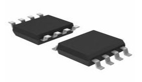
IL511 Package

IL511 Manufacturer
NVE is a leader in spintronics, nanotechnology. NVE licenses MRAM intellectual property and sells Giant Magnetoresistive (GMR) sensors and isolators.
Datasheet PDF
- Datasheets :
What is IL500-Series Isolators?
IL500-Series Isolators are a cost-effective alternative to digital optocouplers in a number of applications including serial interfaces, isolated Serial Peripheral Interface (SPI), isolated A/D converters, and isolated power interfaces.
 XRP7675 Step-Down Regulator: Pinout, Features and Datasheet
16 March 2022758
 AD8138ARZ High-Speed Differential Amplifier: 320MHz Bandwidth, Low Distortion for Precision Applications
23 July 2025257
 LM358 Dual Op-Amp: Pinout, Equivalent and Datasheet
03 December 202119228
 HMC462LP5 Low Noise Amplifier: Datasheet, Pinout, Price
20 December 2021353
 STM32F302VEH6 Microcontroller: 72MHz, 100-UFBGA, Pinout and Features
19 January 2022259
 MPX2010DP Pressure Sensor: MPX2010DP Datasheet and Block Diagram
28 March 20223945
 CD4049 Buffer and Converter IC: Pinout, Equivalent and Datasheet
28 August 20216519
 LTC6752IMS8-2#TRPBF Linear Comparator: Product Overview and Applications
06 March 2024204
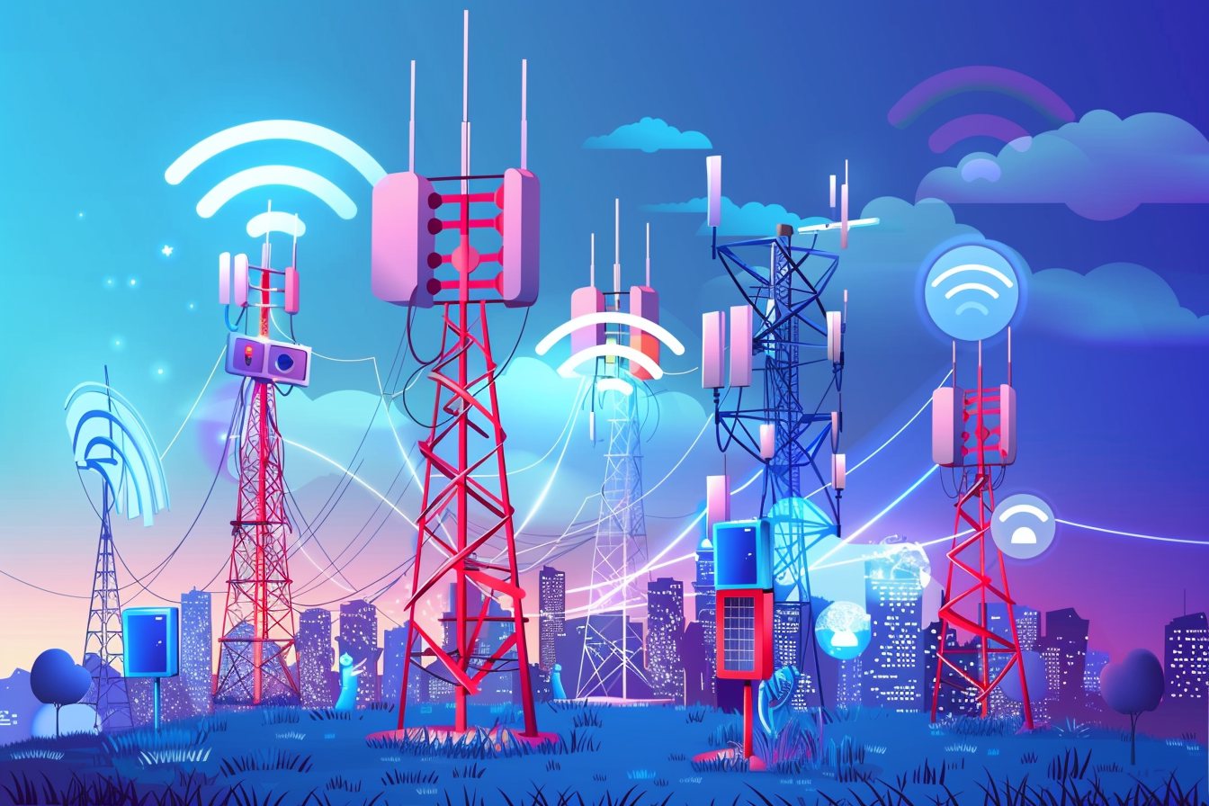 ‘6G Networks’ - Pioneering the Next Era of Connectivity And Innovation
18 March 20243339
 CR2450 vs CR2032 Batteries
18 June 20251646
 Microwave Diode: Introduction and Types
07 January 202124002
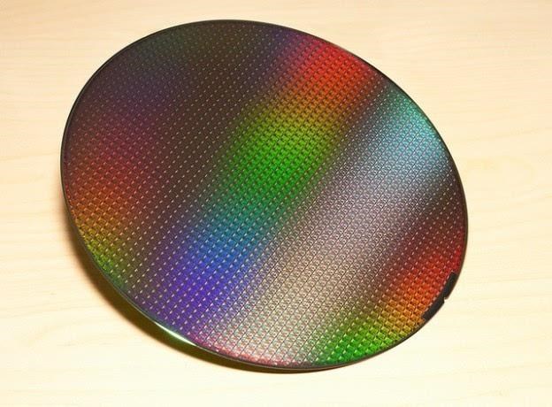 Analysis of Semiconductor Wafers
22 October 202514319
 Challenges and Control Approaches for Current Sharing in DC Microgrids
07 June 20234726
 Beginner’s Handbook for Choosing Circular Connectors
14 July 20253175
 State-of-Charge Estimation Techniques for Lithium-Ion Batteries
26 January 20242198
 Intel Launches First-of-its-Kind Semiconductor Technician Certificate Program to Address Workforce Shortage
28 September 20233251
NVE Corp/Isolation Products
In Stock: 500
Minimum: 1 Multiples: 1
Qty
Unit Price
Ext Price
1
$4.700512
$4.70
10
$4.434445
$44.34
100
$4.183439
$418.34
500
$3.946641
$1,973.32
1000
$3.723246
$3,723.25
Not the price you want? Send RFQ Now and we'll contact you ASAP.
Inquire for More Quantity
![IL 717-3E]() IL 717-3E
IL 717-3ENVE Corp/Isolation Products
![IL 712-1E]() IL 712-1E
IL 712-1ENVE Corp/Isolation Products
![IL 41050TTVE]() IL 41050TTVE
IL 41050TTVENVE Corp/Isolation Products
![IL 711T-3E]() IL 711T-3E
IL 711T-3ENVE Corp/Isolation Products
![IL 41050TE]() IL 41050TE
IL 41050TENVE Corp/Isolation Products
![IL 610-1E]() IL 610-1E
IL 610-1ENVE Corp/Isolation Products
![IL 711-1E]() IL 711-1E
IL 711-1ENVE Corp/Isolation Products
![IL 261-1ETR7]() IL 261-1ETR7
IL 261-1ETR7NVE Corp/Isolation Products
![IL 710-1ETR7]() IL 710-1ETR7
IL 710-1ETR7NVE
![IL 710T-1ETR7]()


