
IM03GR Signal Relays: Features, Pinout, CAD Model

TE Connectivity Potter & Brumfield Relays
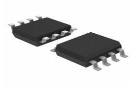
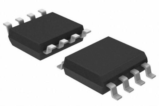
Signal Relay 5VDC 2A DPDT( (10mm 7.5mm 5.65mm)) SMD Automotive


Signal Relay 5VDC 2A DPDT( (10mm 7.5mm 5.65mm)) SMD Automotive
TE Connectivity's IM03GR is a signal relay module. This article mainly introduces Features, Pinout, CAD Model and other detailed information about TE Connectivity Potter & Brumfield Relays IM03GR.
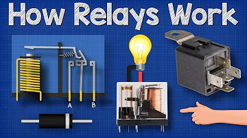
How Relays Work - Basic working principle electronics engineering electrician amp
IM03GR Description
TE Connectivity's IM03GR is a signal relay module. The IM series is a narrow line, low-profile electromechanical power relay with a height of 5.65mm that is commonly used in small devices. Standard and high dielectric, high current, and high contact stability relays are among the models available in the IM series. It has a high dielectric and surge capability of up to 2500Vrms between the open contacts and 3000Vrms between the coil and the contacts.
IM03GR Pinout

IM03GR CAD Model


IM03GR Features
• Slim line 10x6mm, low profile 5.65mm and min. board-space 60mm2
• Switching current 2/5A, switching power 60W/62.5VA and switching voltage 220VDC/250VAC
• Low coil power consumption,
140mW standard, 100mW for high sensitive version, 50mW for ultra high sensitive version and 100mW for bistable version
• High dielectric and surge capability up to 2500Vrms between open contacts and 2500Vrms between coil and contacts
• High mechanical shock resistance up to 50g functional
• DPDT contact form
• Switching power is 60W
• Monostable , bistable versions available
• Coil voltage ranges from 1.5 to 24VDC
• UL standard approved
• Through hole and SMD terminals available
Specifications
- TypeParameter
- Factory Lead Time2 Weeks
- Mounting Type
The "Mounting Type" in electronic components refers to the method used to attach or connect a component to a circuit board or other substrate, such as through-hole, surface-mount, or panel mount.
Surface Mount - Surface Mount
having leads that are designed to be soldered on the side of a circuit board that the body of the component is mounted on.
NO - Weight0.75g
- End Contact Plating
End contact plating refers to the process of applying a thin layer of metal coating to the contact points at the ends of electronic components. This plating serves several purposes, including enhancing the electrical conductivity of the contacts, preventing corrosion, and improving solderability. The choice of plating material can vary depending on the specific requirements of the component, with common options including gold, silver, tin, and nickel. Proper end contact plating is essential for ensuring reliable electrical connections and overall performance of electronic components.
GOLD ALLOY - CoilResistance178Ohm
- Contact MaterialsPalladium (Pd), Ruthenium (Ru), Gold (Au)
- ElectricalLife100000 Cycle(s)
- Isolation-Max-18.8 dB
- Operating Frequency (Max)900MHz
- Operating Temperature
The operating temperature is the range of ambient temperature within which a power supply, or any other electrical equipment, operate in. This ranges from a minimum operating temperature, to a peak or maximum operating temperature, outside which, the power supply may fail.
-40°C~85°C - Packaging
Semiconductor package is a carrier / shell used to contain and cover one or more semiconductor components or integrated circuits. The material of the shell can be metal, plastic, glass or ceramic.
Cut Tape (CT) - Series
In electronic components, the "Series" refers to a group of products that share similar characteristics, designs, or functionalities, often produced by the same manufacturer. These components within a series typically have common specifications but may vary in terms of voltage, power, or packaging to meet different application needs. The series name helps identify and differentiate between various product lines within a manufacturer's catalog.
IM, AXICOM - Published2007
- Pbfree Code
The "Pbfree Code" parameter in electronic components refers to the code or marking used to indicate that the component is lead-free. Lead (Pb) is a toxic substance that has been widely used in electronic components for many years, but due to environmental concerns, there has been a shift towards lead-free alternatives. The Pbfree Code helps manufacturers and users easily identify components that do not contain lead, ensuring compliance with regulations and promoting environmentally friendly practices. It is important to pay attention to the Pbfree Code when selecting electronic components to ensure they meet the necessary requirements for lead-free applications.
yes - Part Status
Parts can have many statuses as they progress through the configuration, analysis, review, and approval stages.
Active - Moisture Sensitivity Level (MSL)
Moisture Sensitivity Level (MSL) is a standardized rating that indicates the susceptibility of electronic components, particularly semiconductors, to moisture-induced damage during storage and the soldering process, defining the allowable exposure time to ambient conditions before they require special handling or baking to prevent failures
3 (168 Hours) - Number of Terminations8
- ECCN Code
An ECCN (Export Control Classification Number) is an alphanumeric code used by the U.S. Bureau of Industry and Security to identify and categorize electronic components and other dual-use items that may require an export license based on their technical characteristics and potential for military use.
EAR99 - Additional Feature
Any Feature, including a modified Existing Feature, that is not an Existing Feature.
RELEASE TIME WITH DIODE IN PARALLEL - HTS Code
HTS (Harmonized Tariff Schedule) codes are product classification codes between 8-1 digits. The first six digits are an HS code, and the countries of import assign the subsequent digits to provide additional classification. U.S. HTS codes are 1 digits and are administered by the U.S. International Trade Commission.
8536.49.00.50 - Packing Method
The packing method in electronic components refers to the technique used to package and protect the component during shipping and handling. It encompasses various forms including tape and reel, tray, tube, or bulk packaging, each suited for different types of components and manufacturing processes. The choice of packing method can affect the ease of handling, storage, and the efficiency of assembly in automated processes. Additionally, it plays a crucial role in ensuring the reliability and integrity of the components until they are used in electronic devices.
BOX; TR - Reference Standard
In the context of electronic components, the term "Reference Standard" typically refers to a specific set of guidelines, specifications, or requirements that serve as a benchmark for evaluating the quality, performance, and characteristics of the component. These standards are established by organizations such as the International Electrotechnical Commission (IEC), the Institute of Electrical and Electronics Engineers (IEEE), or specific industry bodies.Reference standards help ensure consistency and interoperability among different components, as they provide a common framework for manufacturers, designers, and users to adhere to. They outline parameters such as electrical properties, mechanical dimensions, environmental conditions, and safety considerations that the component must meet to be considered compliant.By referencing these standards, manufacturers can design and produce components that meet industry-recognized criteria, which in turn helps users select the right components for their applications with confidence. Adhering to reference standards also facilitates regulatory compliance and promotes overall quality and reliability in electronic systems.
CSA; UL - Termination Style
"Termination style" in electronic components refers to the method used to connect the component to a circuit board or other electronic devices. It determines how the component's leads or terminals are designed for soldering or mounting onto the circuit board. Common termination styles include through-hole, surface mount, and wire lead terminations.Through-hole components have leads that are inserted through holes in the circuit board and soldered on the other side. Surface mount components have flat terminals that are soldered directly onto the surface of the circuit board. Wire lead terminations involve attaching wires to the component for connection.The choice of termination style depends on factors such as the type of component, the manufacturing process, and the space available on the circuit board. Different termination styles offer various advantages in terms of ease of assembly, reliability, and space efficiency in electronic designs.
Gull Wing - Body Length or Diameter
Body length or diameter in electronic components refers to the physical dimensions of a component's housing, typically measured in millimeters or inches. It indicates the size of the component that affects its fit within a circuit board or system. This parameter is crucial for ensuring compatibility with the design and mounting of electronic devices. It can impact heat dissipation, electrical performance, and overall assembly efficiency. Accurate measurement of body length or diameter is essential for proper component selection and placement in electronic applications.
10mm - Body Breadth
Body breadth in electronic components refers to the width of the physical body of a component, such as a resistor, capacitor, or integrated circuit. This measurement is crucial for ensuring proper fit within a circuit board or enclosure. It can affect the component's thermal performance, mechanical stability, and overall compatibility with other components in a design. Body breadth is typically specified in millimeters or inches and is an important factor in the selection and design of electronic assemblies.
6 mm - Physical Dimension
The parameter "Physical Dimension" in electronic components refers to the measurable size and shape characteristics of a component. This includes dimensions such as length, width, height, and diameter, which are critical for ensuring proper fit and integration into electronic circuits and systems. Physical dimensions also influence the component's performance, thermal management, and overall reliability in application environments. Understanding these dimensions is essential for designers to maintain compatibility with circuit boards and reduce issues related to space constraints.
10mm x 6mm x 5.65mm - Contact Resistance
Contact resistance refers to the resistance encountered at the point of contact between two conductive materials or components. It is a measure of how well the two materials make electrical contact with each other. High contact resistance can lead to voltage drops, power losses, and inefficient electrical connections. It is typically measured in ohms and is an important parameter to consider in electronic components such as connectors, switches, and relays. Lower contact resistance is desirable for ensuring reliable and efficient electrical connections in electronic circuits.
50mOhm - Insulation Resistance
The measurement of insulation resistance is carried out by means of a megohmmeter – high resistance range ohmmeter. A general rule-of-thumb is 10 Megohm or more.
1000000000Ohm - Sealing
Sealing in electronic components refers to the process of enclosing and protecting sensitive parts from environmental factors such as moisture, dust, and chemicals. This is essential for ensuring the reliability and longevity of the components. Sealing is achieved through various methods, including the use of potting compounds, encapsulation materials, or hermetic sealing techniques. Proper sealing enhances the performance and durability of electronic devices in demanding applications.
IP67 - Contact Voltage(DC)-Max
Contact Voltage(DC)-Max refers to the maximum allowable direct current voltage that can be applied across the contacts of an electronic component without causing permanent damage or failure. It indicates the threshold above which electrical breakdown may occur, potentially harming the component's functionality. This parameter is crucial for ensuring the reliability and safety of components in various applications, as exceeding this value can lead to insulation breakdown or overheating.
220V - Contact Form
A page on a website that allows users to communicate with the site owner. The page has fields for filling in name, address and type of comment. On most company websites, email and mailing addresses are also included; however, the contact form provides an immediate, convenient way for users to ask the company questions.
DPDT (2 Form C) - Relay Type
In electronic components, the parameter "Relay Type" refers to the specific classification or categorization of a relay based on its design, functionality, and application. Relays are electromechanical devices that are used to control the switching of circuits by opening or closing contacts in response to an electrical signal. The relay type typically indicates the specific characteristics of the relay, such as its switching mechanism (e.g., electromagnetic, solid-state), contact configuration (e.g., SPST, DPDT), operating voltage, current rating, and intended use (e.g., power relays, signal relays, automotive relays). Understanding the relay type is important for selecting the right relay for a particular application to ensure proper functionality and reliability.
Telecom - Operate Time
The time interval between the instant of the occurrence of a specified input condition to a system and the instant of completion of a specified operation.
3ms - Coil Voltage
Coil voltage refers to the electrical potential difference that is applied across the coil of an electromechanical device, such as a relay or a solenoid. This voltage is essential for energizing the coil, creating a magnetic field that enables the device to perform its intended function, such as opening or closing contacts. The coil voltage is specified by the manufacturer and varies depending on the design and application of the component, commonly available in standard values like 5V, 12V, 24V, and others. Proper selection of coil voltage is crucial for optimal performance and longevity of the device.
5VDC - Coil Type
There are 2 different types of 'coil'; one has copper on it (IUD) and the other contains hormone (Mirena IUS). Both are over 99% effective at protecting against pregnancy.
Non Latching - Switching Voltage
The maximum switching voltage of a relay is the maximum voltage that can be across the contacts whether the relay is open or closed. Operating a relay with high voltages present can cause arcing, and this in turn erodes the contacts and eventually degrades contact performance.
250VAC 220VDC -Max - Coil Current
A current coil is basically a coil, such as, a wire wrapped around an electrical conductor.
28mA - Release Time
In telecommunication, release time is the time interval for a circuit to respond when an enabling signal is discontinued
10 ms - Must Operate Voltage
Must Operate Voltage is the minimum voltage level at which an electronic component or device is guaranteed to function correctly. Below this threshold, the component may experience performance issues, erratic behavior, or complete failure to operate. It is a critical specification for ensuring reliable operation in various applications where voltage variations can occur.
3.75VDC - Contact Rating (Current)
Contact Rating (Current) is a parameter used to specify the maximum current that an electronic component's contact can handle without causing damage or failure. It is typically expressed in amperes (A) and is crucial for ensuring the safe and reliable operation of the component within a circuit. Exceeding the specified contact rating can lead to overheating, arcing, or even permanent damage to the component. Therefore, it is important to carefully consider the contact rating when designing or selecting components for a circuit to prevent potential hazards and ensure optimal performance.
2A - Coil Power
Coil Power in electronic components refers to the amount of power consumed by a coil or inductor when an electrical current passes through it. It is a measure of the energy dissipated as heat within the coil due to its resistance. The coil power is typically specified in watts and is important to consider when designing circuits to ensure that the coil can handle the power without overheating. Properly managing coil power is crucial for the overall performance and reliability of electronic systems.
140mW - Must Release Voltage
Must Release Voltage is the minimum voltage level that an electronic component, such as a relay or circuit breaker, requires to safely disengage or reset its mechanical operation. This parameter ensures that the component can reliably return to a non-energized state when power is removed or when a control signal goes low. It is an important specification for ensuring proper operation and safety in electronic circuits where the component may be exposed to fluctuating voltages.
0.5VDC - Contact Voltage(AC)-Max
Contact Voltage(AC)-Max refers to the maximum alternating current voltage that an electronic component can safely handle at its contact points. This parameter is critical for ensuring the safe and effective operation of devices in AC circuits. Exceeding this voltage can lead to failure or damage of the component, making it essential for designers to adhere to specified voltage ratings.
250V - Contact/Output Supply Type
Contact/Output Supply Type is a parameter used to describe the type of connection or output supply required for an electronic component to function properly. This parameter specifies the specific type of contact or supply needed for the component to receive power or transmit signals. It can include details such as the number of pins, voltage levels, current requirements, and communication protocols. Understanding the Contact/Output Supply Type is crucial for selecting compatible components and ensuring proper functionality within an electronic system.
AC/DC - Relay Action
Relay action refers to the type of mechanical movement performed by a relay in response to an electrical signal. It typically describes how the relay transitions between its open and closed states to either allow or interrupt the flow of current in a circuit. Relay action can be classified as normally open or normally closed, indicating the default state of the relay contacts before any current is applied. The speed and responsiveness of this action can significantly affect the performance of the overall circuit in which the relay is used.
MOMENTARY - Coil/Input Supply Type
Coil/Input Supply Type refers to the voltage and current specifications required to operate the coil in electromagnetic components such as relays and solenoids. This parameter indicates whether the component is designed to operate with AC or DC voltage sources and specifies the nominal voltage level for optimal performance. Understanding the Coil/Input Supply Type is essential for ensuring proper operation and compatibility with circuit designs.
DC - Operating Frequency-Min
Operating Frequency-Min is a parameter in electronic components that specifies the minimum frequency at which the component can function reliably. This parameter is crucial for determining the performance and compatibility of the component within a given system or circuit. It indicates the lowest frequency at which the component can operate without experiencing issues such as signal degradation, timing errors, or malfunctions. Designers and engineers use this specification to ensure that the component will meet the required performance criteria under specific operating conditions.
100MHz - VSWR
VSWR stands for Voltage Standing Wave Ratio, and it is a measure of how efficiently radio frequency (RF) power is transmitted from a source, such as a transmitter, to a load, such as an antenna, through a transmission line. It is a dimensionless ratio that compares the maximum voltage in a standing wave pattern to the minimum voltage in that pattern along the transmission line. A VSWR value of 1 indicates perfect impedance matching, meaning all the power is being efficiently transferred without any reflections. Higher VSWR values indicate a mismatch in impedance, which can lead to power loss, signal degradation, and potential damage to components. VSWR is an important parameter in RF systems to ensure optimal performance and signal integrity.
1.49 - Seal Rating
Seal Rating in electronic components refers to the level of protection the component has against environmental factors such as dust, moisture, and other contaminants. It is a measure of how well the component is sealed to prevent these external elements from entering and potentially damaging the internal circuitry. The seal rating is typically represented by an IP (Ingress Protection) code, which consists of two digits. The first digit indicates the level of protection against solid particles, while the second digit indicates the level of protection against liquids. A higher seal rating indicates a greater level of protection against environmental factors.
Sealed - Hermetically - Insertion Loss (Max)
Insertion Loss (Max) is a parameter used to measure the amount of signal loss that occurs when a component is inserted into a circuit. It is typically expressed in decibels (dB) and represents the maximum amount of signal attenuation that can be expected when the component is in use. A higher insertion loss value indicates greater signal loss, which can impact the overall performance of the circuit. It is important to consider the insertion loss when designing or selecting components for a circuit to ensure that the desired signal integrity and performance requirements are met.
-0.33 dB - Dielectric Strength Between Open Contacts
The parameter "Dielectric Strength Between Open Contacts" in electronic components refers to the maximum voltage that can be applied across open contacts without causing electrical breakdown or arcing. It is a measure of the insulation capability of the material between the contacts. When the dielectric strength is exceeded, the insulating material may break down, leading to a short circuit or other electrical issues. This parameter is important in ensuring the reliability and safety of electronic components, especially in high-voltage applications where maintaining proper insulation is critical. Manufacturers provide dielectric strength specifications to help designers and engineers select components that can withstand the required voltage levels without failure.
1000 Vrms - Input Switching Control Type
Input Switching Control Type refers to the method or mechanism used to control the switching of inputs in electronic components such as switches, relays, or multiplexers. This parameter determines how the selection of different input channels is managed within the component. Common types of input switching control include manual control, where a user physically selects the input channel, and automatic control, where the switching is done based on predetermined criteria or signals. The choice of input switching control type can impact the functionality, flexibility, and ease of use of the electronic component in various applications.
Random - Dielectric Strength Between Coil and Contacts
The parameter "Dielectric Strength Between Coil and Contacts" in electronic components refers to the maximum voltage that can be applied between the coil and the contacts without causing electrical breakdown or insulation failure. It is a critical specification that indicates the insulation capability of the component and its ability to withstand high voltage levels. A higher dielectric strength value indicates better insulation properties and increased reliability in preventing electrical arcing or short circuits between the coil and contacts. This parameter is important in ensuring the safe and reliable operation of the electronic component in various applications where high voltages may be present.
1800 Vrms - Contact (AC) Max Power Rating R Load
The parameter "Contact (AC) Max Power Rating R Load" in electronic components refers to the maximum power that can be safely handled by the contacts when carrying an alternating current (AC) load. This rating is important for ensuring that the contacts do not overheat or fail when carrying the specified power level. It is typically expressed in watts and helps determine the suitability of the component for a particular application where AC power is involved. Manufacturers provide this specification to guide users in selecting components that can reliably handle the required power levels without experiencing damage or performance degradation.
62.5VA@250VAC - Contact (DC) Max Power Rating R Load
The parameter "Contact (DC) Max Power Rating R Load" in electronic components refers to the maximum amount of power that can be safely handled by the contacts of the component when a direct current (DC) load is applied. This rating is important to ensure that the contacts do not overheat or fail when carrying current. It is typically specified in watts and helps determine the suitability of the component for a particular application where power dissipation is a concern. It is crucial to adhere to this rating to prevent damage to the component and ensure reliable operation in the circuit.
60W@220VDC - Coil Operate Voltage(DC)
Coil Operate Voltage (DC) refers to the direct current voltage level required to energize the coil of an electromagnetic component, such as a relay or solenoid. This voltage is essential for activating the component, allowing it to perform its intended function. If the applied voltage is below the specified coil operate voltage, the component may not engage properly or may fail to operate altogether. Conversely, applying a voltage significantly higher than the rated value may result in overheating or damage to the coil.
3.5V - Switching Time
Switching time in electronic components refers to the time it takes for a device to change its state from one condition to another. It is a crucial parameter in determining the speed and efficiency of electronic circuits. The switching time is typically measured as the time taken for a signal to transition between specified voltage levels, such as from high to low or vice versa. Faster switching times indicate a more responsive and high-performance component, while slower switching times can lead to delays and inefficiencies in the circuit operation. Overall, understanding and optimizing the switching time of electronic components is essential for designing reliable and efficient electronic systems.
18 ms - Body Height
In electronic components, "Body Height" refers to the vertical dimension of the component's physical body or package. It is the measurement from the bottom of the component to the top, excluding any leads or terminals. Body Height is an important parameter to consider when designing circuit boards or enclosures to ensure proper fit and clearance. It is typically specified in datasheets or technical drawings provided by the component manufacturer. Understanding the Body Height of electronic components is crucial for proper placement and integration within a circuit or system.
5.65mm - RoHS Status
RoHS means “Restriction of Certain Hazardous Substances” in the “Hazardous Substances Directive” in electrical and electronic equipment.
RoHS Compliant
IM03GR Applications
• Telecommunication
• Access and Transmission Equipment
• Optical Network
• Terminals, Modems
• Office and Business Equipment
• Consumer Electronics
• Measurement and Test Equipment
• Industrial Control, Medical Equipment
• HVAC
• Industrial
• Power Management
• Automation & Process Control
• Test & Measurement
• Automotive
• Portable Devices
IM03GR Package


IM03GR Manufacturer
Many industries are served by TE Connectivity P&B, originally Tyco Electronics P&B, including appliance, HVAC, industrial control, computer peripheral, and security. P&B has a wide range of relays and circuit breakers to fulfill your needs. For PC board and panel/plug-in mounting, electromechanical, solid state, and time delay relays are available. Circuit breakers, both thermal and magnetic.
Datasheet PDF
- PCN Design/Specification :
- PCN Packaging :
- 3D Drawings :
What is a Signal Relays?
Signal relays offer superior contact reliability even with a small signal load owing to its gold-pasted contact and bifurcated crossbar structure.
What is the height of the IM03GR?
5.65mm.
What is the dielectric and surge capability between open contacts?
2500Vrms.
 BC557B Transistors: Pinout, Features and Datasheet
28 September 20213783
 RT9193 Ultra-Fast CMOS LDO Regulator: Datasheet pdf, Ultra-Fast Regulator and Specifications
26 November 20213585
 DW01A Battery Protection IC: Datasheet pdf, Schematic and Alternatives
19 November 202113376
 SP2502LBTG TVS Diode: Pinout, Datasheet, Schematic
30 August 2021464
 LM211QD Voltage Comparator Overview
14 August 2024782
 CD4001BE: Overview, Applications and Datasheet
09 November 20231679
 ATMEGA32U4 Microcontroller: Pinout, Datasheet and Equivalents
09 July 202112401
 PCA9555 CMOS Device: Datasheet, Pinout, Application Circuit
21 October 20214780
 What is MCU Decryption?
17 January 20221658
 How to Address IoT Eco-security in the Era of Digital Transformation?
22 April 2022533
 Optical Image Stabilization (OIS) Explained: Types and Working
21 May 202110528
 Working and Types of Touch Screen
20 March 20215810
 How does the CPU recognize the Code?
08 August 20221122
 Semiconductor Memory Market to See More Significant Price Declines
17 August 2022956
 A Study of the Interelectrode Capacitances of SiC and GaN Power Semiconductor Devices Using Multiple Current Probes
01 February 20231092
 What is G.654E Fiber?
24 May 20225171
TE Connectivity Potter & Brumfield Relays
In Stock: 6575
United States
China
Canada
Japan
Russia
Germany
United Kingdom
Singapore
Italy
Hong Kong(China)
Taiwan(China)
France
Korea
Mexico
Netherlands
Malaysia
Austria
Spain
Switzerland
Poland
Thailand
Vietnam
India
United Arab Emirates
Afghanistan
Åland Islands
Albania
Algeria
American Samoa
Andorra
Angola
Anguilla
Antigua & Barbuda
Argentina
Armenia
Aruba
Australia
Azerbaijan
Bahamas
Bahrain
Bangladesh
Barbados
Belarus
Belgium
Belize
Benin
Bermuda
Bhutan
Bolivia
Bonaire, Sint Eustatius and Saba
Bosnia & Herzegovina
Botswana
Brazil
British Indian Ocean Territory
British Virgin Islands
Brunei
Bulgaria
Burkina Faso
Burundi
Cabo Verde
Cambodia
Cameroon
Cayman Islands
Central African Republic
Chad
Chile
Christmas Island
Cocos (Keeling) Islands
Colombia
Comoros
Congo
Congo (DRC)
Cook Islands
Costa Rica
Côte d’Ivoire
Croatia
Cuba
Curaçao
Cyprus
Czechia
Denmark
Djibouti
Dominica
Dominican Republic
Ecuador
Egypt
El Salvador
Equatorial Guinea
Eritrea
Estonia
Eswatini
Ethiopia
Falkland Islands
Faroe Islands
Fiji
Finland
French Guiana
French Polynesia
Gabon
Gambia
Georgia
Ghana
Gibraltar
Greece
Greenland
Grenada
Guadeloupe
Guam
Guatemala
Guernsey
Guinea
Guinea-Bissau
Guyana
Haiti
Honduras
Hungary
Iceland
Indonesia
Iran
Iraq
Ireland
Isle of Man
Israel
Jamaica
Jersey
Jordan
Kazakhstan
Kenya
Kiribati
Kosovo
Kuwait
Kyrgyzstan
Laos
Latvia
Lebanon
Lesotho
Liberia
Libya
Liechtenstein
Lithuania
Luxembourg
Macao(China)
Madagascar
Malawi
Maldives
Mali
Malta
Marshall Islands
Martinique
Mauritania
Mauritius
Mayotte
Micronesia
Moldova
Monaco
Mongolia
Montenegro
Montserrat
Morocco
Mozambique
Myanmar
Namibia
Nauru
Nepal
New Caledonia
New Zealand
Nicaragua
Niger
Nigeria
Niue
Norfolk Island
North Korea
North Macedonia
Northern Mariana Islands
Norway
Oman
Pakistan
Palau
Palestinian Authority
Panama
Papua New Guinea
Paraguay
Peru
Philippines
Pitcairn Islands
Portugal
Puerto Rico
Qatar
Réunion
Romania
Rwanda
Samoa
San Marino
São Tomé & Príncipe
Saudi Arabia
Senegal
Serbia
Seychelles
Sierra Leone
Sint Maarten
Slovakia
Slovenia
Solomon Islands
Somalia
South Africa
South Sudan
Sri Lanka
St Helena, Ascension, Tristan da Cunha
St. Barthélemy
St. Kitts & Nevis
St. Lucia
St. Martin
St. Pierre & Miquelon
St. Vincent & Grenadines
Sudan
Suriname
Svalbard & Jan Mayen
Sweden
Syria
Tajikistan
Tanzania
Timor-Leste
Togo
Tokelau
Tonga
Trinidad & Tobago
Tunisia
Turkey
Turkmenistan
Turks & Caicos Islands
Tuvalu
U.S. Outlying Islands
U.S. Virgin Islands
Uganda
Ukraine
Uruguay
Uzbekistan
Vanuatu
Vatican City
Venezuela
Wallis & Futuna
Yemen
Zambia
Zimbabwe