
 Product
 Brand
Brand Articles
 Tools
Tools
LT1500CS Regulator: Pinout, Block Diagram, Datasheet

Linear Technology/Analog Devices
14 Terminals LT1500 DC DC Voltage Regulator SWITCHING REGULATOR Tube 14-SOIC (0.154, 3.90mm Width)


14 Terminals LT1500 DC DC Voltage Regulator SWITCHING REGULATOR Tube 14-SOIC (0.154, 3.90mm Width)
The LT1500CS is an adaptive-frequency current mode step-up switching regulator with an internal power switch that is rated up to 700mA. This article will unlock more detailed information about LT1500CS.
LT1500CS Pinout

LT1500CS Description
The LT1500CS is an adaptive-frequency current mode step-up switching regulator with an internal power switch that is rated up to 700mA. In contrast to pulse skipping switching regulators, the LT1500CS uses a current mode topology that provides lower noise operation and improved efficiency.
Specifications
- TypeParameter
- Mounting Type
The "Mounting Type" in electronic components refers to the method used to attach or connect a component to a circuit board or other substrate, such as through-hole, surface-mount, or panel mount.
Surface Mount - Package / Case
refers to the protective housing that encases an electronic component, providing mechanical support, electrical connections, and thermal management.
14-SOIC (0.154, 3.90mm Width) - Surface Mount
having leads that are designed to be soldered on the side of a circuit board that the body of the component is mounted on.
YES - Operating Temperature (Max.)70°C
- Packaging
Semiconductor package is a carrier / shell used to contain and cover one or more semiconductor components or integrated circuits. The material of the shell can be metal, plastic, glass or ceramic.
Tube - JESD-609 Code
The "JESD-609 Code" in electronic components refers to a standardized marking code that indicates the lead-free solder composition and finish of electronic components for compliance with environmental regulations.
e0 - Part Status
Parts can have many statuses as they progress through the configuration, analysis, review, and approval stages.
Obsolete - Moisture Sensitivity Level (MSL)
Moisture Sensitivity Level (MSL) is a standardized rating that indicates the susceptibility of electronic components, particularly semiconductors, to moisture-induced damage during storage and the soldering process, defining the allowable exposure time to ambient conditions before they require special handling or baking to prevent failures
1 (Unlimited) - Number of Terminations14
- ECCN Code
An ECCN (Export Control Classification Number) is an alphanumeric code used by the U.S. Bureau of Industry and Security to identify and categorize electronic components and other dual-use items that may require an export license based on their technical characteristics and potential for military use.
EAR99 - Terminal Finish
Terminal Finish refers to the surface treatment applied to the terminals or leads of electronic components to enhance their performance and longevity. It can improve solderability, corrosion resistance, and overall reliability of the connection in electronic assemblies. Common finishes include nickel, gold, and tin, each possessing distinct properties suitable for various applications. The choice of terminal finish can significantly impact the durability and effectiveness of electronic devices.
Tin/Lead (Sn/Pb) - HTS Code
HTS (Harmonized Tariff Schedule) codes are product classification codes between 8-1 digits. The first six digits are an HS code, and the countries of import assign the subsequent digits to provide additional classification. U.S. HTS codes are 1 digits and are administered by the U.S. International Trade Commission.
8542.39.00.01 - Terminal Position
In electronic components, the term "Terminal Position" refers to the physical location of the connection points on the component where external electrical connections can be made. These connection points, known as terminals, are typically used to attach wires, leads, or other components to the main body of the electronic component. The terminal position is important for ensuring proper connectivity and functionality of the component within a circuit. It is often specified in technical datasheets or component specifications to help designers and engineers understand how to properly integrate the component into their circuit designs.
DUAL - Terminal Form
Occurring at or forming the end of a series, succession, or the like; closing; concluding.
GULL WING - Number of Functions1
- Terminal Pitch
The center distance from one pole to the next.
1.27mm - Reach Compliance Code
Reach Compliance Code refers to a designation indicating that electronic components meet the requirements set by the Registration, Evaluation, Authorization, and Restriction of Chemicals (REACH) regulation in the European Union. It signifies that the manufacturer has assessed and managed the chemical substances within the components to ensure safety and environmental protection. This code is vital for compliance with regulations aimed at minimizing risks associated with hazardous substances in electronic products.
not_compliant - Base Part Number
The "Base Part Number" (BPN) in electronic components serves a similar purpose to the "Base Product Number." It refers to the primary identifier for a component that captures the essential characteristics shared by a group of similar components. The BPN provides a fundamental way to reference a family or series of components without specifying all the variations and specific details.
LT1500 - Pin Count
a count of all of the component leads (or pins)
14 - JESD-30 Code
JESD-30 Code refers to a standardized descriptive designation system established by JEDEC for semiconductor-device packages. This system provides a systematic method for generating designators that convey essential information about the package's physical characteristics, such as size and shape, which aids in component identification and selection. By using JESD-30 codes, manufacturers and engineers can ensure consistency and clarity in the specification of semiconductor packages across various applications and industries.
R-PDSO-G14 - Qualification Status
An indicator of formal certification of qualifications.
Not Qualified - Output Voltage
Output voltage is a crucial parameter in electronic components that refers to the voltage level produced by the component as a result of its operation. It represents the electrical potential difference between the output terminal of the component and a reference point, typically ground. The output voltage is a key factor in determining the performance and functionality of the component, as it dictates the level of voltage that will be delivered to the connected circuit or load. It is often specified in datasheets and technical specifications to ensure compatibility and proper functioning within a given system.
1.265V - Input Voltage-Nom
Input Voltage-Nom refers to the nominal or rated input voltage that an electronic component or device is designed to operate within. This parameter specifies the voltage level at which the component is expected to function optimally and safely. It is important to ensure that the actual input voltage supplied to the component does not exceed this nominal value to prevent damage or malfunction. Manufacturers provide this specification to guide users in selecting the appropriate power supply or input voltage source for the component. It is a critical parameter to consider when designing or using electronic circuits to ensure reliable performance and longevity of the component.
2.3V - Temperature Grade
Temperature grades represent a tire's resistance to heat and its ability to dissipate heat when tested under controlled laboratory test conditions.
COMMERCIAL - Analog IC - Other Type
Analog IC - Other Type is a parameter used to categorize electronic components that are integrated circuits (ICs) designed for analog signal processing but do not fall into more specific subcategories such as amplifiers, comparators, or voltage regulators. These ICs may include specialized analog functions such as analog-to-digital converters (ADCs), digital-to-analog converters (DACs), voltage references, or signal conditioning circuits. They are typically used in various applications where precise analog signal processing is required, such as in audio equipment, instrumentation, communication systems, and industrial control systems. Manufacturers provide detailed specifications for these components to help engineers select the most suitable IC for their specific design requirements.
SWITCHING REGULATOR - Input Voltage (Min)
Input Voltage (Min) is a parameter in electronic components that specifies the minimum voltage level required for the component to operate properly. It indicates the lowest voltage that can be safely applied to the component without causing damage or malfunction. This parameter is crucial for ensuring the reliable and safe operation of the component within its specified operating range. It is important for designers and engineers to consider the minimum input voltage requirement when selecting and using electronic components in their circuits to prevent potential issues such as underperformance or failure.
1.8V - Control Mode
In electronic components, "Control Mode" refers to the method or mode of operation used to regulate or control the behavior of the component. This parameter determines how the component responds to input signals or commands to achieve the desired output. The control mode can vary depending on the specific component and its intended function, such as voltage regulation, current limiting, or frequency modulation. Understanding the control mode of an electronic component is crucial for proper integration and operation within a circuit or system.
CURRENT-MODE - Output Current-Max
Output Current-Max is a parameter in electronic components that specifies the maximum amount of current that can be safely drawn from the output of the component without causing damage. It is an important specification to consider when designing circuits to ensure that the component can handle the required current without overheating or failing. Exceeding the maximum output current can lead to performance issues, component damage, or even complete failure of the circuit. It is crucial to adhere to the specified maximum output current to ensure the reliable operation of the electronic component and the overall circuit.
1.3A - Input Voltage (Max)
Input Voltage (Max) refers to the maximum voltage that an electronic component can safely handle without getting damaged. This parameter is crucial for ensuring the proper functioning and longevity of the component. Exceeding the maximum input voltage can lead to overheating, electrical breakdown, or even permanent damage to the component. It is important to carefully consider and adhere to the specified maximum input voltage when designing or using electronic circuits to prevent any potential issues or failures.
15V - Supply Current-Max (Isup)
Supply Current-Max (Isup) refers to the maximum amount of current that an electronic component can draw from its power supply during operation. It represents the peak current demand of the device under normal operating conditions and is critical for ensuring that the power supply can adequately support the component's needs without risking damage or malfunction. This parameter is essential for designing circuits and selecting appropriate power supply units to prevent overloading and ensure reliable performance.
0.32mA - Switcher Configuration
Switcher Configuration in electronic components refers to the arrangement or setup of a switcher circuit, which is a type of power supply that converts one form of electrical energy into another. The configuration of a switcher circuit includes the specific components used, such as transistors, diodes, capacitors, and inductors, as well as their interconnections and control mechanisms. The switcher configuration determines the efficiency, voltage regulation, and other performance characteristics of the power supply. Different switcher configurations, such as buck, boost, buck-boost, and flyback, are used for various applications depending on the desired output voltage and current requirements. Understanding and selecting the appropriate switcher configuration is crucial in designing reliable and efficient power supply systems for electronic devices.
BOOST - Switching Frequency-Max
Switching Frequency-Max is a parameter in electronic components that refers to the maximum frequency at which the device can switch on and off within a given period of time. This parameter is crucial in determining the performance and efficiency of the component, especially in applications such as power supplies, inverters, and motor drives. A higher switching frequency allows for faster operation and can result in smaller component sizes, reduced power losses, and improved overall system performance. However, it is important to consider the trade-offs between switching frequency, efficiency, and heat dissipation to ensure optimal operation of the electronic component.
500kHz - Length8.65mm
- Height Seated (Max)
Height Seated (Max) is a parameter in electronic components that refers to the maximum allowable height of the component when it is properly seated or installed on a circuit board or within an enclosure. This specification is crucial for ensuring proper fit and alignment within the overall system design. Exceeding the maximum seated height can lead to mechanical interference, electrical shorts, or other issues that may impact the performance and reliability of the electronic device. Manufacturers provide this information to help designers and engineers select components that will fit within the designated space and function correctly in the intended application.
1.75mm - Width3.9mm
- RoHS Status
RoHS means “Restriction of Certain Hazardous Substances” in the “Hazardous Substances Directive” in electrical and electronic equipment.
Non-RoHS Compliant
LT1500CS Features
■ Low Noise Adaptive-Frequency Current Mode Operation Avoids Low-Frequency Noise at Most Load Currents
■ Can Be Externally Synchronized (LT1500)
■ Micro-power Quiescent Current: 200µA
■ Shutdown Current: 8µA Type
■ Internal Loop Compensation
■ Low-Battery Comparator Active in Shutdown
■ Minimum Input Voltage: 1.8V Type
■ Additional Negative Voltage Feedback Pin (LT1500)
■ Up to 500kHz Switching Frequency
■ Uses Low Profile, Low-Cost Surface Mount Inductors
LT1500CS Block Diagram
The LT1500CS uses a current mode architecture without the need for an internal oscillator. Switching frequency is determined by the value of the external inductor used. This technique allows the selection of an operating frequency best suited to each application and considerably simplifies the internal circuitry needed. So we can see the block diagram below.

LT1500CS Application
■ Portable Instrumentation
■ Battery Operated Systems
■ PDA's
■ Standby Power
LT1500CS Typical Application Circuit
The LT1500 operates with input voltages from1.8V to 15V and have only a 200µA operating current dropping to 8µA in shutdown. A low-battery comparator is included which stays alive in shutdown. A second output feedback pin with negative polarity allows negative output voltages to be regulated when the switcher is connected up as a Cuk or a flyback converter.

The typical application circuit is shown above.
LT1500CS Package

LT1500CS Manufacturer
Analog Devices (NASDAQ: ADI) is a world leader in the design, manufacture, and marketing of a broad portfolio of high-performance analogue, mixed-signal, and digital signal processing (DSP) integrated circuits (ICs) used in virtually all types of electronic equipment. Since our inception in 1965, we have focused on solving the engineering challenges associated with signal processing in electronic equipment.
Datasheet PDF
- Datasheets :
What is LT1500CS?
The LT1500CS is an adaptive-frequency current mode step-up switching regulator with an internal power switch that is rated up to 700mA. In contrast to pulse skipping switching regulators, the LT1500CS uses a current mode topology that provides lower noise operation and improved efficiency.
What package is the LT1500CS available in?
The LT1500CS comes in a 14-pin SO package, with two options available for fixed output (3.3V or 5V) or adjustable operation.
What does LT1500CS operate with?
The LT1500CS operates with input voltages from1.8V to 15V and has only a 200µA operating current dropping to 8µA in shutdown.
 TDA7492P Audio Amplifier: Datasheet, Applications Circuit, and Pinout
26 July 20213950
 PIC10F200 Microcontroller: Circuit, Pinout, and Datasheet
26 October 20214362
 IRF640S Power MOSFET: Datasheet, IRF640 MOSFET, Pinout
11 August 20212053
 AT89C5115 Microcontroller: Comprehensive Overview and Applications
29 February 2024120
 OV7670 Camera Module: Datasheet, Specifications and Comparison
05 November 202116127
 STM8AL31E8x STM8AL3LE8x Ultra-Low-Power 8-Bit Family Datasheet Summary
29 February 2024105
 TL494 Control Circuit: Features, Specifications and Applications
13 May 20213232
 6N139 Optocoupler: Pinout, Applications and Datasheet
13 August 20212405
 Silicon Carbide (SiC): The Third-generation Semiconductor Material
30 August 20219228
 Step-by-Step Guide to 2.2 k Ohm Resistor Color Code in 2025
20 August 20252175
 Is there a Limit to the Chip Process Node?
02 November 202119511
 What is Resistor?
02 November 20216809
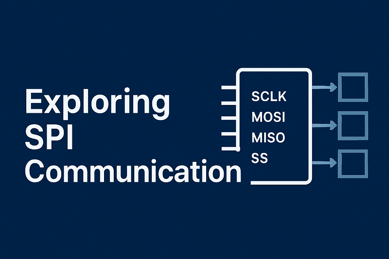 Exploring SPI Communication for Faster Data Transfer
20 June 2025748
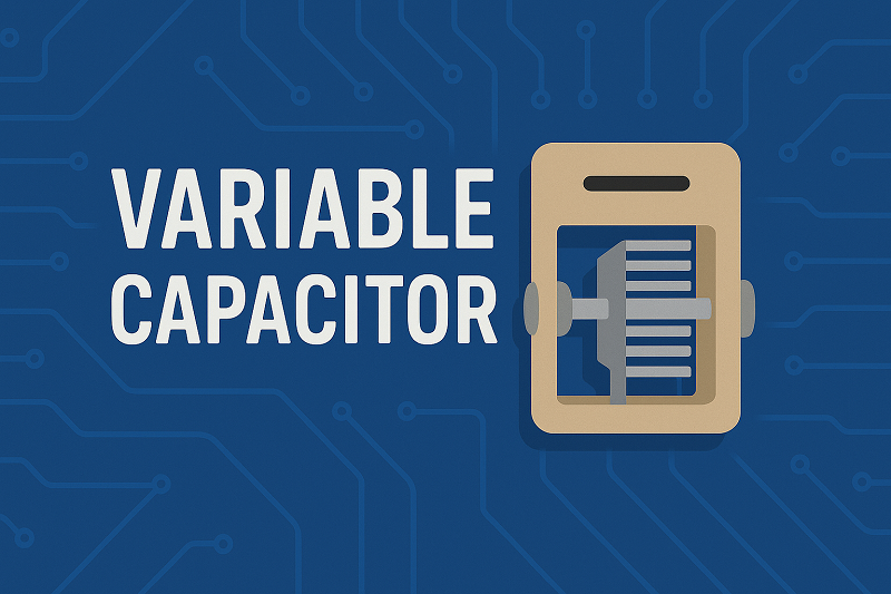 What is a variable capacitor?
16 April 202560978
 Introduction to Coupling Capacitor
04 February 20215632
 BSNPC Inverters in Photovoltaic Applications Using SiC and GaN
04 January 20234033
Linear Technology/Analog Devices
In Stock
United States
China
Canada
Japan
Russia
Germany
United Kingdom
Singapore
Italy
Hong Kong(China)
Taiwan(China)
France
Korea
Mexico
Netherlands
Malaysia
Austria
Spain
Switzerland
Poland
Thailand
Vietnam
India
United Arab Emirates
Afghanistan
Åland Islands
Albania
Algeria
American Samoa
Andorra
Angola
Anguilla
Antigua & Barbuda
Argentina
Armenia
Aruba
Australia
Azerbaijan
Bahamas
Bahrain
Bangladesh
Barbados
Belarus
Belgium
Belize
Benin
Bermuda
Bhutan
Bolivia
Bonaire, Sint Eustatius and Saba
Bosnia & Herzegovina
Botswana
Brazil
British Indian Ocean Territory
British Virgin Islands
Brunei
Bulgaria
Burkina Faso
Burundi
Cabo Verde
Cambodia
Cameroon
Cayman Islands
Central African Republic
Chad
Chile
Christmas Island
Cocos (Keeling) Islands
Colombia
Comoros
Congo
Congo (DRC)
Cook Islands
Costa Rica
Côte d’Ivoire
Croatia
Cuba
Curaçao
Cyprus
Czechia
Denmark
Djibouti
Dominica
Dominican Republic
Ecuador
Egypt
El Salvador
Equatorial Guinea
Eritrea
Estonia
Eswatini
Ethiopia
Falkland Islands
Faroe Islands
Fiji
Finland
French Guiana
French Polynesia
Gabon
Gambia
Georgia
Ghana
Gibraltar
Greece
Greenland
Grenada
Guadeloupe
Guam
Guatemala
Guernsey
Guinea
Guinea-Bissau
Guyana
Haiti
Honduras
Hungary
Iceland
Indonesia
Iran
Iraq
Ireland
Isle of Man
Israel
Jamaica
Jersey
Jordan
Kazakhstan
Kenya
Kiribati
Kosovo
Kuwait
Kyrgyzstan
Laos
Latvia
Lebanon
Lesotho
Liberia
Libya
Liechtenstein
Lithuania
Luxembourg
Macao(China)
Madagascar
Malawi
Maldives
Mali
Malta
Marshall Islands
Martinique
Mauritania
Mauritius
Mayotte
Micronesia
Moldova
Monaco
Mongolia
Montenegro
Montserrat
Morocco
Mozambique
Myanmar
Namibia
Nauru
Nepal
New Caledonia
New Zealand
Nicaragua
Niger
Nigeria
Niue
Norfolk Island
North Korea
North Macedonia
Northern Mariana Islands
Norway
Oman
Pakistan
Palau
Palestinian Authority
Panama
Papua New Guinea
Paraguay
Peru
Philippines
Pitcairn Islands
Portugal
Puerto Rico
Qatar
Réunion
Romania
Rwanda
Samoa
San Marino
São Tomé & Príncipe
Saudi Arabia
Senegal
Serbia
Seychelles
Sierra Leone
Sint Maarten
Slovakia
Slovenia
Solomon Islands
Somalia
South Africa
South Sudan
Sri Lanka
St Helena, Ascension, Tristan da Cunha
St. Barthélemy
St. Kitts & Nevis
St. Lucia
St. Martin
St. Pierre & Miquelon
St. Vincent & Grenadines
Sudan
Suriname
Svalbard & Jan Mayen
Sweden
Syria
Tajikistan
Tanzania
Timor-Leste
Togo
Tokelau
Tonga
Trinidad & Tobago
Tunisia
Turkey
Turkmenistan
Turks & Caicos Islands
Tuvalu
U.S. Outlying Islands
U.S. Virgin Islands
Uganda
Ukraine
Uruguay
Uzbekistan
Vanuatu
Vatican City
Venezuela
Wallis & Futuna
Yemen
Zambia
Zimbabwe
![LTC1624CS8#PBF]() LTC1624CS8#PBF
LTC1624CS8#PBFAnalogDevices
![LT8609EMSE#TRPBF]() LT8609EMSE#TRPBF
LT8609EMSE#TRPBFLinear Technology/Analog Devices
![LT1933ES6#TRPBF]() LT1933ES6#TRPBF
LT1933ES6#TRPBFLinear Technology/Analog Devices
![LT1054IS8#TRPBF]() LT1054IS8#TRPBF
LT1054IS8#TRPBFLinear Technology/Analog Devices
![ADP1613ARMZ-R7]() ADP1613ARMZ-R7
ADP1613ARMZ-R7Analog Devices Inc.
![LT1933ES6#TRMPBF]() LT1933ES6#TRMPBF
LT1933ES6#TRMPBFLinear Technology/Analog Devices
![ADM660ARZ]() ADM660ARZ
ADM660ARZAnalog Devices Inc.
![LT8609SIV#PBF]() LT8609SIV#PBF
LT8609SIV#PBFLinear Technology/Analog Devices
![LT1376HVCS8#PBF]() LT1376HVCS8#PBF
LT1376HVCS8#PBFLinear Technology/Analog Devices
![LT3508EFE#PBF]() LT3508EFE#PBF
LT3508EFE#PBFLinear Technology/Analog Devices


