

 Product
 Brand
Brand Articles
 Tools
Tools
MAX3243IPW Transceiver: Pinout,Specification, and Datasheet

28 Terminations 28 Pin MAX3243 Receivers 3/5 Drivers/Receivers 3 Functions
Unit Price: $0.641243
Ext Price: $0.64


28 Terminations 28 Pin MAX3243 Receivers 3/5 Drivers/Receivers 3 Functions
The MAX3243IPW achieves a 1µA supply current with Maxim's revolutionary AutoShutdown™ feature.
MAX3243IPW Description
When the MAX3243 does not sense a valid signal level on their receiver inputs, the onboard power supply and drivers shut down. This occurs if the RS-232 cable is disconnected or if the transmitters of the connected peripherals are turned off. The system turns on again when a valid level is applied to any RS-232 receiver input.
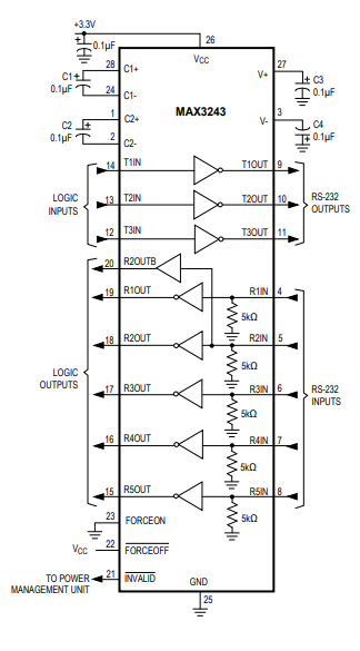
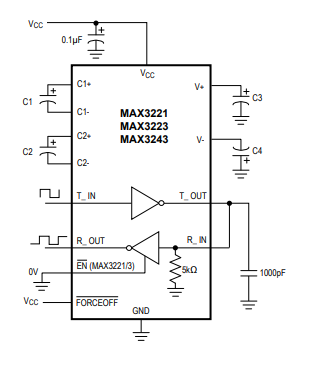
The MAX3243 requires only 0.1µF capacitors in 3.3V operation, and can operate from input voltages ranging from +3.0V to +5.5V.
A proprietary, high-efficiency, dual charge-pump power supply and a low-dropout transmitter combine to deliver true RS-232 performance from a single +3.0V to +5.5V supply.
The MAX3243 is a 3-driver/5-receiver with a complementary always-active receiver for external monitoring in a variety of 28 pin packages. See Order Information table for package offerings.
MAX3243IPW Features
● Integrated charge pump circuitry simplifies power requirements
• Eliminates the need for a ±12 supply
• Operation from a single +3.3V or +5V supply
● 1µA supply current in shutdown mode saves power
• Auto-shutdown feature is enabled after no activity on receiver inputs for 30µs
• Software control option for shutdown
MAX3243IPW Applicaitons
● Battery-powered equipment
● Hand-held equipment
● Peripherals
● Portable diagnostics equipment
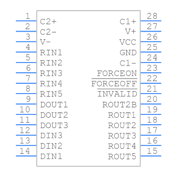
MAX3243IPW Pinout
Specifications
- TypeParameter
- Factory Lead Time6 Weeks
- Mount
In electronic components, the term "Mount" typically refers to the method or process of physically attaching or fixing a component onto a circuit board or other electronic device. This can involve soldering, adhesive bonding, or other techniques to secure the component in place. The mounting process is crucial for ensuring proper electrical connections and mechanical stability within the electronic system. Different components may have specific mounting requirements based on their size, shape, and function, and manufacturers provide guidelines for proper mounting procedures to ensure optimal performance and reliability of the electronic device.
Surface Mount - Mounting Type
The "Mounting Type" in electronic components refers to the method used to attach or connect a component to a circuit board or other substrate, such as through-hole, surface-mount, or panel mount.
Surface Mount - Package / Case
refers to the protective housing that encases an electronic component, providing mechanical support, electrical connections, and thermal management.
28-TSSOP (0.173, 4.40mm Width) - Number of Pins28
- Weight117.508773mg
- Current - Supply (Nom)1mA
- Number of I/Os16
- Operating Temperature
The operating temperature is the range of ambient temperature within which a power supply, or any other electrical equipment, operate in. This ranges from a minimum operating temperature, to a peak or maximum operating temperature, outside which, the power supply may fail.
-40°C~85°C - Packaging
Semiconductor package is a carrier / shell used to contain and cover one or more semiconductor components or integrated circuits. The material of the shell can be metal, plastic, glass or ceramic.
Tube - JESD-609 Code
The "JESD-609 Code" in electronic components refers to a standardized marking code that indicates the lead-free solder composition and finish of electronic components for compliance with environmental regulations.
e4 - Pbfree Code
The "Pbfree Code" parameter in electronic components refers to the code or marking used to indicate that the component is lead-free. Lead (Pb) is a toxic substance that has been widely used in electronic components for many years, but due to environmental concerns, there has been a shift towards lead-free alternatives. The Pbfree Code helps manufacturers and users easily identify components that do not contain lead, ensuring compliance with regulations and promoting environmentally friendly practices. It is important to pay attention to the Pbfree Code when selecting electronic components to ensure they meet the necessary requirements for lead-free applications.
yes - Part Status
Parts can have many statuses as they progress through the configuration, analysis, review, and approval stages.
ACTIVE (Last Updated: 4 days ago) - Moisture Sensitivity Level (MSL)
Moisture Sensitivity Level (MSL) is a standardized rating that indicates the susceptibility of electronic components, particularly semiconductors, to moisture-induced damage during storage and the soldering process, defining the allowable exposure time to ambient conditions before they require special handling or baking to prevent failures
1 (Unlimited) - Number of Terminations28
- ECCN Code
An ECCN (Export Control Classification Number) is an alphanumeric code used by the U.S. Bureau of Industry and Security to identify and categorize electronic components and other dual-use items that may require an export license based on their technical characteristics and potential for military use.
EAR99 - TypeTransceiver
- Terminal Finish
Terminal Finish refers to the surface treatment applied to the terminals or leads of electronic components to enhance their performance and longevity. It can improve solderability, corrosion resistance, and overall reliability of the connection in electronic assemblies. Common finishes include nickel, gold, and tin, each possessing distinct properties suitable for various applications. The choice of terminal finish can significantly impact the durability and effectiveness of electronic devices.
Nickel/Palladium/Gold (Ni/Pd/Au) - Voltage - Supply
Voltage - Supply refers to the range of voltage levels that an electronic component or circuit is designed to operate with. It indicates the minimum and maximum supply voltage that can be applied for the device to function properly. Providing supply voltages outside this range can lead to malfunction, damage, or reduced performance. This parameter is critical for ensuring compatibility between different components in a circuit.
5V - Terminal Position
In electronic components, the term "Terminal Position" refers to the physical location of the connection points on the component where external electrical connections can be made. These connection points, known as terminals, are typically used to attach wires, leads, or other components to the main body of the electronic component. The terminal position is important for ensuring proper connectivity and functionality of the component within a circuit. It is often specified in technical datasheets or component specifications to help designers and engineers understand how to properly integrate the component into their circuit designs.
DUAL - Terminal Form
Occurring at or forming the end of a series, succession, or the like; closing; concluding.
GULL WING - Peak Reflow Temperature (Cel)
Peak Reflow Temperature (Cel) is a parameter that specifies the maximum temperature at which an electronic component can be exposed during the reflow soldering process. Reflow soldering is a common method used to attach electronic components to a circuit board. The Peak Reflow Temperature is crucial because it ensures that the component is not damaged or degraded during the soldering process. Exceeding the specified Peak Reflow Temperature can lead to issues such as component failure, reduced performance, or even permanent damage to the component. It is important for manufacturers and assemblers to adhere to the recommended Peak Reflow Temperature to ensure the reliability and functionality of the electronic components.
260 - Number of Functions3
- Base Part Number
The "Base Part Number" (BPN) in electronic components serves a similar purpose to the "Base Product Number." It refers to the primary identifier for a component that captures the essential characteristics shared by a group of similar components. The BPN provides a fundamental way to reference a family or series of components without specifying all the variations and specific details.
MAX3243 - Output Voltage
Output voltage is a crucial parameter in electronic components that refers to the voltage level produced by the component as a result of its operation. It represents the electrical potential difference between the output terminal of the component and a reference point, typically ground. The output voltage is a key factor in determining the performance and functionality of the component, as it dictates the level of voltage that will be delivered to the connected circuit or load. It is often specified in datasheets and technical specifications to ensure compatibility and proper functioning within a given system.
13.2V - Output Current
The rated output current is the maximum load current that a power supply can provide at a specified ambient temperature. A power supply can never provide more current that it's rated output current unless there is a fault, such as short circuit at the load.
35mA - Propagation Delay
the flight time of packets over the transmission link and is limited by the speed of light.
150 ns - Logic Function
In electronic components, the term "Logic Function" refers to the specific operation or behavior of a component based on its input signals. It describes how the component processes the input signals to produce the desired output. Logic functions are fundamental to digital circuits and are used to perform logical operations such as AND, OR, NOT, and XOR.Each electronic component, such as logic gates or flip-flops, is designed to perform a specific logic function based on its internal circuitry. By understanding the logic function of a component, engineers can design and analyze complex digital systems to ensure proper functionality and performance. Different logic functions can be combined to create more complex operations, allowing for the creation of sophisticated digital devices and systems.
Receiver, Transceiver - Data Rate
Data Rate is defined as the amount of data transmitted during a specified time period over a network. It is the speed at which data is transferred from one device to another or between a peripheral device and the computer. It is generally measured in Mega bits per second(Mbps) or Mega bytes per second(MBps).
250kbps - Differential Output
a differential output voltage in electronics is the difference between the values of two AC voltages, 180° out of phase, present at the output terminals of an amplifier when you apply a differential input voltage to the input terminals of an amplifier.
NO - Output Polarity
Output polarity in electronic components refers to the orientation of the output signal in relation to the ground or reference voltage. It indicates whether the output voltage is positive or negative with respect to the ground. Positive output polarity means the signal is higher than the ground potential, while negative output polarity signifies that the signal is lower than the ground. This characteristic is crucial for determining compatibility with other components in a circuit and ensuring proper signal processing.
INVERTED - Protocol
In electronic components, the parameter "Protocol" refers to a set of rules and standards that govern the communication between devices. It defines the format, timing, sequencing, and error checking methods for data exchange between different components or systems. Protocols ensure that devices can understand and interpret data correctly, enabling them to communicate effectively with each other. Common examples of protocols in electronics include USB, Ethernet, SPI, I2C, and Bluetooth, each with its own specifications for data transmission. Understanding and adhering to protocols is essential for ensuring compatibility and reliable communication between electronic devices.
RS232 - Input Characteristics
In electronic components, "Input Characteristics" refer to the set of specifications that describe how the component behaves in response to signals or inputs applied to it. These characteristics typically include parameters such as input voltage, input current, input impedance, input capacitance, and input frequency range. Understanding the input characteristics of a component is crucial for designing circuits and systems, as it helps ensure compatibility and proper functioning. By analyzing these parameters, engineers can determine how the component will interact with the signals it receives and make informed decisions about its use in a particular application.
SCHMITT TRIGGER - Number of Drivers/Receivers3/5
- Duplex
In the context of electronic components, "Duplex" refers to a type of communication system that allows for bidirectional data flow. It enables two devices to communicate with each other simultaneously, allowing for both sending and receiving of data at the same time. Duplex communication can be further categorized into two types: half-duplex, where data can be transmitted in both directions but not at the same time, and full-duplex, where data can be sent and received simultaneously. This parameter is crucial in networking and telecommunications systems to ensure efficient and effective data transmission between devices.
Full - Receiver Hysteresis
Receiver hysteresis is?commonly used to ensure glitch-free reception even when differential noise is present. This application report compares the noise immunity of the SN65HVD37 to similar devices available from competitors. Contents.
500mV - Number of Drivers3
- Number of Transceivers1
- Simplex/Duplex
In electronic components, the parameter "Simplex/Duplex" refers to the type of communication or data transmission mode supported by the component. Simplex communication is a one-way communication mode where data flows only in one direction, from the sender to the receiver. This means that the sender can only transmit data, and the receiver can only receive data. On the other hand, duplex communication is a two-way communication mode where data can flow in both directions, allowing for simultaneous transmission and reception of data between two devices. Understanding whether a component supports simplex or duplex communication is important for determining how data will be exchanged between devices and ensuring compatibility in a given system.
Full Duplex - Supply Voltage1-Nom
Supply Voltage1-Nom is a parameter in electronic components that refers to the nominal or rated voltage level at which the component is designed to operate optimally. This parameter specifies the voltage level that the component requires to function correctly and efficiently. It is important to ensure that the actual supply voltage provided to the component closely matches the specified nominal voltage to prevent damage or malfunction. Deviating significantly from the nominal voltage may result in unreliable performance or even permanent damage to the component. It is crucial to adhere to the specified supply voltage range to ensure the proper functioning and longevity of the electronic component.
3.3V - Number of Receivers5
- Out Swing-Min
Out Swing-Min is a parameter in electronic components that indicates the minimum voltage level that an output signal can reach when the device is in a low state. It is critical for determining the output swing of digital circuits, particularly in logic devices and amplifiers. This parameter helps to ensure that the output can properly drive the subsequent stage of a circuit or meet the logic level requirements of connected components. A lower Out Swing-Min value may enhance compatibility with other devices in terms of signal integrity.
5 V - Height1.2mm
- Length9.7mm
- Width4.4mm
- Thickness
Thickness in electronic components refers to the measurement of how thick a particular material or layer is within the component structure. It can pertain to various aspects, such as the thickness of a substrate, a dielectric layer, or conductive traces. This parameter is crucial as it impacts the electrical, mechanical, and thermal properties of the component, influencing its performance and reliability in electronic circuits.
1mm - REACH SVHC
The parameter "REACH SVHC" in electronic components refers to the compliance with the Registration, Evaluation, Authorization, and Restriction of Chemicals (REACH) regulation regarding Substances of Very High Concern (SVHC). SVHCs are substances that may have serious effects on human health or the environment, and their use is regulated under REACH to ensure their safe handling and minimize their impact.Manufacturers of electronic components need to declare if their products contain any SVHCs above a certain threshold concentration and provide information on the safe use of these substances. This information allows customers to make informed decisions about the potential risks associated with using the components and take appropriate measures to mitigate any hazards.Ensuring compliance with REACH SVHC requirements is essential for electronics manufacturers to meet regulatory standards, protect human health and the environment, and maintain transparency in their supply chain. It also demonstrates a commitment to sustainability and responsible manufacturing practices in the electronics industry.
No SVHC - Radiation Hardening
Radiation hardening is the process of making electronic components and circuits resistant to damage or malfunction caused by high levels of ionizing radiation, especially for environments in outer space (especially beyond the low Earth orbit), around nuclear reactors and particle accelerators, or during nuclear accidents or nuclear warfare.
No - RoHS Status
RoHS means “Restriction of Certain Hazardous Substances” in the “Hazardous Substances Directive” in electrical and electronic equipment.
ROHS3 Compliant - Lead Free
Lead Free is a term used to describe electronic components that do not contain lead as part of their composition. Lead is a toxic material that can have harmful effects on human health and the environment, so the electronics industry has been moving towards lead-free components to reduce these risks. Lead-free components are typically made using alternative materials such as silver, copper, and tin. Manufacturers must comply with regulations such as the Restriction of Hazardous Substances (RoHS) directive to ensure that their products are lead-free and environmentally friendly.
Lead Free
MAX3243IPW CAD Model
Symbol
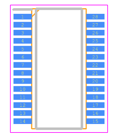
Footprint
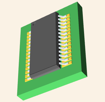
3D Model
MAX3243IPW Typical Operating Circuit
MAX3243IPW Loopback Test Circuit
MAX3243IPW Manufacturer
Trend Analysis
Datasheet PDF
- Datasheets :
 ATTINY2313-20PU AVR ATtiny Microcontroller 20MHz 20-pin DIP: Datasheet, Pinout, and Features
25 February 20222252
 OP249 Dual Op-Amp: Pinout, Applications and Datasheet
10 December 20212072
 1N914 vs. 1N4148: What Difference is between 1N914 and 1N4148?
23 November 202111847
 2SC828 NPN Amplifier Transistor: Datasheet, Replacement and Pinout
27 October 20213900
 A Comprehensive Guide to the PIC18F4520IML Microcontroller
29 February 2024392
 TLC59116IPWR LED sink driver: Datasheet, Pinout, and Specifications
25 March 20222923
 LR44 Battery: Equivalent, Specifications and Replacements
05 November 2021156885
 STM32F401VDH6 Microcontroller: Pinout, Datasheet, Features
29 July 20214590
 Wiring and Mounting Photoelectric Sensors in 2025
15 July 20251741
 Understanding SiC MOSFET Power Modules and Ensuring its Short-Circuit Safety
15 March 20244489
 2026 Memory: Strategic Sourcing Tactics for DRAM & NAND Price Hikes
07 July 20263192
 Semiconductor Market Poised for Strong Rebound in 2024, Predicts WSTS
11 December 20235403
 A Beginner's Guide to the 2N5551 Transistor and Its Uses
27 May 20256693
 Introduction to AC motor
05 March 20219875
 Comparing Heat Sink Types for Modern Applications
19 July 20253826
 What is SMT (Surface Mount Technology)?
02 December 20219007
Texas Instruments
In Stock: 6200
Minimum: 1 Multiples: 1
Qty
Unit Price
Ext Price
1
$0.641243
$0.64
10
$0.604946
$6.05
100
$0.570704
$57.07
500
$0.538400
$269.20
1000
$0.507925
$507.92
Not the price you want? Send RFQ Now and we'll contact you ASAP.
Inquire for More Quantity
![DS14C89AMX]() DS14C89AMX
DS14C89AMXTexas Instruments
![DS90LV031ATMTCX]() DS90LV031ATMTCX
DS90LV031ATMTCXTexas Instruments
![THS6092IDR]() THS6092IDR
THS6092IDRTexas Instruments
![TRSF3232IDBR]() TRSF3232IDBR
TRSF3232IDBRTexas Instruments
![SN75176BP]() SN75176BP
SN75176BPTexas Instruments
![SN65HVD251D]() SN65HVD251D
SN65HVD251DTexas Instruments
![SN65HVD230DR]() SN65HVD230DR
SN65HVD230DRTexas Instruments
![SN65176BDR]() SN65176BDR
SN65176BDRTexas Instruments
![SN65HVD12D]() SN65HVD12D
SN65HVD12DTexas Instruments
![SN65HVD234D]() SN65HVD234D
SN65HVD234DTexas Instruments


