
 Product
 Brand
Brand Articles
 Tools
Tools
Maxim Integrated DS2431+ Guide for Easy Electronics Projects


Through Hole 3 Pin Memory IC DS2431 1 kb kb 4.95mm mm
Maxim Integrated DS2431+ offers simple 1-Wire memory expansion for electronics, enabling secure data storage and easy integration with microcontrollers.
Product Introduction
You can easily add extra memory to your electronics projects with the maxim integrated ds2431+. This chip stores your data even when you turn off the power. You only need one wire to connect and communicate with the maxim integrated ds2431+, which makes your work simple. Many people call it a "message in a chip" because you can store important information safely. If you follow the basic steps, you will find using this chip both easy and fun.
What Is the Maxim Integrated DS2431+?
Overview
You can think of the maxim integrated ds2431+ as a tiny helper for your electronics projects. This chip stores information even when you turn off your device. It works as a non-volatile EEPROM memory device with a storage capacity of 1Kbit, organized as 256 x 4 bits. You use a single wire to talk to the chip, which makes it easy to connect and control. Many people call it a message in a chip because you can save important data and read it back whenever you need. The maxim integrated ds2431+ gives you a simple way to add memory to your circuits. You do not need many wires or complicated setups. You can use it with many microcontrollers, so it fits into lots of different projects.
Benefits
The maxim integrated ds2431+ offers several advantages over other memory chips. You get a small, reliable, and easy-to-use solution for storing data. Here are some key benefits:
| Advantage Category | Details |
|---|---|
| Memory Size & Organization | 1Kbit EEPROM with 256 x 4 memory organization |
| Interface | 1-Wire® interface enabling simple, single-line communication |
| Power Consumption | Low power consumption suitable for energy-sensitive applications |
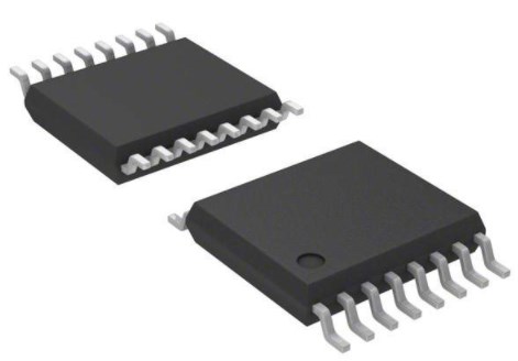
| Package Size | Small package size (TO-226-3, TO-92-3) for compact integration |
| Access Time | Fast access time of 2 µs |
| Operating Temperature Range | Wide range from -40°C to 85°C, suitable for diverse environments |
| Reliability & Compliance | RoHS3 compliant, Moisture Sensitivity Level 1 (unlimited), REACH unaffected |
| Performance | Robust and reliable for long-term applications |
| Cost-effectiveness | Economical solution for small memory needs |
| Compatibility | Compatible with various microcontrollers supporting 1-Wire® protocol |
You can use the maxim ds2431 in many places where you need to store small amounts of data. The chip works well in harsh environments and uses very little power. You can trust it to keep your data safe for a long time.
Key Features
Memory Organization
You get a clear and simple memory structure with the Maxim Integrated DS2431+. This 1k 1-wire eeprom stores 1024 bits of data. The memory splits into four pages, each with 256 bits. Each page holds 32 bytes, and you can use these pages to organize your data. The eeprom uses a 1-Wire interface, so you only need one data line to connect it to your microcontroller.
Here is a quick look at the memory details:
| Feature | Description |
|---|---|
| Memory Size | 1Kb (1024 bits) |
| Memory Organization | 4 pages of 256 bits each |
| Memory Type | EEPROM (non-volatile) |
| Memory Interface | 1-Wire interface |
You can store sensor readings, device IDs, or small logs in this eeprom. The memory keeps your data safe even when you turn off the power. You can read and write to any page, which gives you flexibility for many projects.
Write Protection
You can protect your data with the write protection feature. Each page in the eeprom has its own write protection setting. When you enable write protection, you stop any changes to that page. This helps you keep important information safe from accidental overwrites. For example, you can lock a page after saving a device ID or calibration value. The chip uses this feature to act like a small, secure vault for your data.
Tip: Always double-check your data before enabling write protection. Once you lock a page, you cannot change it again.
Voltage and Package
The Maxim Integrated DS2431+ works in many environments. The chip comes in small packages like TO-92-3 and TO-226-3. These packages fit easily into breadboards and circuit boards. You can use the chip in temperatures from -40°C to 85°C, so it works well indoors and outdoors.
Here is a summary of the technical specifications:
| Specification | Details |
|---|---|
| Memory Size | 1024 bits (1 Kbit) |
| Memory Organization | 256 x 4 bits |
| Memory Type | EEPROM |
| Interface | 1-Wire |
| Access Time | 2 microseconds |
| Operating Temperature | -40°C to 85°C |
| Packaging Options | TO-92-3, TO-226-3 (TO-226AA) |
| Manufacturer | Maxim Integrated / Analog Devices Inc. |
You can rely on this 1-kilobit eeprom for many projects. The eeprom uses very little power and fits into tight spaces. The chip gives you a simple way to add non-volatile memory to your circuits.
Getting Started
Components Needed
You can set up the Maxim Integrated DS2431+ with just a few basic parts. Here is a simple list to help you gather everything you need:
DS2431+ chip, which uses the 1-wire interface for communication.
Power supply that provides between 2.8 V and 5.25 V.
Microcontroller or programmer that supports the 1-wire protocol. Many Arduino and Raspberry Pi boards work well.
Cables or jumper wires to make your connections.
Pull-up resistor, usually 5K ohms, for the 1-wire data line.
Breadboard or PCB for mounting your components.
Computer with the right programming software and drivers if you plan to use a programmer.
You can find most of these items in a basic electronics kit. The 1-wire setup keeps your parts list short and your project simple.
Pinout
The DS2431+ has a straightforward pinout, which makes wiring easy. Here is a table to help you identify each pin:
| Pin Number | Name | Function |
|---|---|---|
| 1 | GND | Ground |
| 2 | DATA | 1-wire data line |
| 3 | VCC | Power supply (2.8–5.25V) |
You connect the 1-wire data line to your microcontroller’s digital pin. The ground and VCC pins go to your power supply. The 1-wire protocol lets you use just one wire for both data and control, which reduces clutter.
Wiring Tips
You can improve your project’s reliability by following a few best practices. Always connect a 5K ohm pull-up resistor between the 1-wire data line and the VCC pin. This resistor helps keep the 1-wire signal stable and prevents communication errors. Place your DS2431+ chip close to your microcontroller to keep the 1-wire line short. Shorter wires reduce noise and make your 1-wire connection more reliable.
Tip: Double-check your connections before powering up. A secure 1-wire setup helps you avoid troubleshooting later.
You can use the 1-wire protocol to connect several DS2431+ chips on the same data line. Each chip has a unique address, so you can talk to each one without extra wires. The 1-wire system makes expanding your project easy and neat.
1-Wire Protocol
Basics
You can use the 1-wire protocol to connect many electronic parts with just one data wire and a ground. This system works as a master-slave communication method. You only need a single wire for both sending and receiving data. Each 1-wire device has a unique 64-bit ID, so you can connect several devices on the same 1-wire bus without confusion.
The 1-wire protocol helps you reduce wiring complexity in your projects. You do not need to run many wires like you would with other systems. The 1-wire bus lets you send both power and data over the same line. Some devices even use parasitic power, drawing energy from the data line itself. This setup makes your circuits neat and easy to build, especially when you want to connect sensors or memory chips far from your main board.
Tip: The 1-wire protocol works well for long-distance connections. You can use it for projects where you need to keep wiring simple and reliable.
Microcontroller Use
You can use many types of microcontrollers with the 1-wire protocol. Arduino boards are very popular for this purpose. You can also use Raspberry Pi boards or Microchip PICmicro microcontrollers. These microcontrollers can talk to the DS2431+ chip and other 1-wire devices using a digital pin.
To connect your DS2431+ to an Arduino, follow these steps:
Place the DS2431+ on your breadboard.
Connect the GND pin of the chip to the GND on your Arduino.
Connect the VCC pin to the 5V pin on your Arduino.
Attach the DATA pin to a digital pin on your Arduino, such as pin 2.
Place a 5K ohm pull-up resistor between the DATA pin and the 5V line.
You can use the same setup for a Raspberry Pi. Just connect the data line to a GPIO pin and use a pull-up resistor. The 1-wire bus allows you to add more devices later without extra wires.
Note: Always check your wiring before turning on your microcontroller. A secure connection helps prevent errors on the 1-wire bus.
Libraries and Code
You can make your project easier by using a library that supports the 1-wire protocol. For Arduino, the "OneWire" library is a good choice. This library helps you send and receive data on the 1-wire bus without writing complex code. You can install it from the Arduino Library Manager.
Here is a simple example code for Arduino that shows how to set up the 1-wire bus and search for connected devices:
#include <OneWire.h>

#define ONE_WIRE_BUS 2  // Pin where DS2431+ is connected

OneWire oneWire(ONE_WIRE_BUS);

void setup() {
  Serial.begin(9600);
  Serial.println("Searching for 1-Wire devices...");
  byte addr[8];
  while (oneWire.search(addr)) {
    Serial.print("Found device with address: ");
    for (int i = 0; i < 8; i++) {
      Serial.print(addr[i], HEX);
      Serial.print(" ");
    }
    Serial.println();
  }
  Serial.println("Done searching.");
}

void loop() {
  // Add your code here to read or write data
}
You can use similar libraries for Raspberry Pi, such as "w1thermsensor" or "python-ow". These libraries help you manage the 1-wire bus and communicate with your DS2431+ chip.
Tip: Always use a library when starting with the 1-wire protocol. It saves time and helps you avoid common mistakes.
Data Operations
Reading
You can read data from the DS2431+ using the 1-wire protocol. The process starts with your microcontroller sending a command to the eeprom. The chip responds by sending back the data stored in its memory. Each DS2431+ has a unique 64-bit address, so you can select the right device even if you have more than one on the same 1-wire bus.
To read data, you follow these steps:
Send a "Read Memory" command to the chip.
Provide the starting address for the data you want.
The chip sends back the data, byte by byte.
The DS2431+ lets you read and write up to 128 characters at a time, depending on your needs. You can use the 1-wire interface to read any part of the 1k 1-wire eeprom. The memory splits into four pages, so you can organize your data and read only what you need.
Tip: Always check the data you receive. The 1-wire protocol supports error checking, which helps you make sure your data is correct.
Here is a simple Arduino code example for reading data:
#include <OneWire.h>

#define ONE_WIRE_BUS 2
OneWire oneWire(ONE_WIRE_BUS);

void setup() {
  Serial.begin(9600);
  byte addr[8];
  if (oneWire.search(addr)) {
    Serial.println("Device found. Reading memory...");
    oneWire.reset();
    oneWire.select(addr);
    oneWire.write(0xF0); // Read Memory command
    oneWire.write(0x00); // Start address LSB
    oneWire.write(0x00); // Start address MSB
    for (int i = 0; i < 8; i++) {
      Serial.print(oneWire.read(), HEX);
      Serial.print(" ");
    }
    Serial.println();
  }
}

void loop() {}
This code reads the first 8 bytes from the eeprom. You can change the address and length to fit your project.
Writing
Writing data to the DS2431+ uses a special process to keep your data safe. The chip uses an 8-byte scratchpad buffer. You first write your data to this scratchpad. This step lets you check the data before you store it in the main eeprom memory.
Follow these steps to write data:
Send the "Write Scratchpad" command (0x0F) with the start address and up to 8 bytes of data.
Read back the scratchpad to verify the data.
If the data matches, send the "Copy Scratchpad" command to move the data from the scratchpad to the eeprom.
This process helps prevent errors. You can only write to one page at a time. Each page holds 32 bytes. If you want to protect your data, you can enable write protection or set EPROM emulation mode for any page.
Once you set a page to EPROM emulation mode, you cannot change it back. In this mode, bits can only change from 1 to 0. You cannot overwrite a 0 with a 1. Write protection and EPROM emulation are permanent. Always double-check before enabling these features.
Here is a simple outline for writing data:
Write data to the scratchpad.
Verify the scratchpad contents.
Copy data to the eeprom.
Enable write protection or EPROM emulation if needed.
You can use the 1-wire protocol to handle all these steps. The process keeps your data safe and reliable.
Memory Map
The DS2431+ uses a simple memory map. The eeprom has 1024 bits, split into four pages of 256 bits each. Each page holds 32 bytes. You can use each page for different types of data, such as sensor logs, device IDs, or settings.
The memory map supports data integrity in several ways:
The 8-byte scratchpad buffer lets you verify data before storing it.
Each page can be write-protected to prevent accidental changes.
EPROM emulation mode allows bits to change only from 1 to 0, which stops overwrites.
The unique 64-bit ROM number ensures you always talk to the right chip on the 1-wire bus.
The 1-wire interface and scratchpad help with error checking and robust data handling.
Here is a table to show the memory structure:
| Page Number | Address Range | Size (bytes) | Write Protection | EPROM Emulation |
|---|---|---|---|---|
| Page 0 | 0x0000-0x001F | 32 | Yes | Yes |
| Page 1 | 0x0020-0x003F | 32 | Yes | Yes |
| Page 2 | 0x0040-0x005F | 32 | Yes | Yes |
| Page 3 | 0x0060-0x007F | 32 | Yes | Yes |
You can set write protection or EPROM emulation for each page. Once you enable these features, you cannot turn them off. This design keeps your important data safe.
Note: The DS2431+ eeprom gives you a reliable way to store data in your electronics projects. The 1-wire protocol makes it easy to connect and manage multiple chips. The scratchpad buffer and memory map help you keep your data organized and secure.
Project Ideas
Data Logger
You can use the DS2431+ eeprom to build a simple data logger. This project lets you collect and store information from sensors, such as temperature or light. You connect your sensor to a microcontroller and write the readings to the eeprom. The memory keeps your data safe, even if you turn off the power. You can read the stored values later and analyze them on your computer. Many students use this idea for science experiments. You can log data over hours or days and see how things change.
Tip: Use one page of the eeprom for each type of sensor reading. This keeps your data organized and easy to find.
Device ID
You can use the DS2431+ as a unique identifier for your project. Every device has its own 64-bit serial number. You can store extra information in the eeprom, such as the owner’s name or the date of manufacture. When your microcontroller reads the device, it can check the serial number and the stored data. This helps you track each device in a group. Many companies use this method to prevent counterfeiting or to keep records of their products.
Example uses:
Assign a unique ID to each sensor in a network.
Store calibration data for each device.
Keep a log of repairs or updates.
More Uses
You can find many creative ways to use the DS2431+ eeprom in your projects. Here are some ideas:
Store passwords or access codes for a security system.
Save user settings for a smart home device.
Keep a record of high scores in a game.
Use the eeprom to remember the last state of a device after a power loss.
The DS2431+ gives you a flexible tool for storing small amounts of important data. You can use it in almost any project that needs reliable memory.
Troubleshooting
Common Issues
You might face some problems when you use the DS2431+ in your projects. Here are some of the most common issues and how you can spot them:
No Communication with the Chip
If your microcontroller cannot find the DS2431+, check your wiring first. Make sure the data line connects to the right pin. The pull-up resistor should be between the data line and VCC. A missing or wrong resistor often causes this problem.Corrupted or Missing Data
If you read back wrong data, you may have a loose connection or too long a wire. Noise on the 1-wire bus can also cause errors. Try to keep wires short and check all connections.Write Failures
Sometimes, you cannot write new data to the chip. This can happen if you enabled write protection or EPROM emulation. Once you lock a page, you cannot change it. Double-check the protection settings before you write.Multiple Devices Not Detected
If you use more than one DS2431+ on the same bus, make sure each device has a unique address. Use the library’s search function to list all connected devices.
Tip: If you see errors, restart your microcontroller and check the power supply. Many problems come from simple wiring mistakes.
Best Practices
You can avoid many problems by following some best practices:
Check Connections
Always double-check your wiring before you power up your project. Secure connections help prevent data loss.Use the Right Resistor
A 5K ohm pull-up resistor works best for most setups. This keeps the 1-wire signal stable.Keep Wires Short
Short wires reduce noise and make communication more reliable. Place the DS2431+ close to your microcontroller.Test with Example Code
Start with simple code examples from trusted libraries. This helps you confirm that your hardware works before you add more features.Label Your Devices
If you use more than one DS2431+, label each chip. This makes it easier to track which device stores which data.
Note: Careful setup and testing save time. You can solve most issues by checking your hardware and using good code examples.
You can add reliable memory to your electronics projects with the Maxim Integrated DS2431+. Start by connecting the chip, use the 1-Wire interface, and write simple code to store your data. Try new ideas and see how the chip fits your needs. Here are some key points to remember:
| Feature | Benefit |
|---|---|
| 1Kbit EEPROM | Stores important data |
| 1-Wire Interface | Easy, single-wire connection |
| Low Power | Saves energy in your project |
| Wide Temperature | Works from -40°C to 85°C |
Explore the DS2431+ in your next build. You will find it simple, flexible, and dependable for many applications.
FAQ
How do you power the DS2431+ chip?
You can power the DS2431+ with any voltage between 2.8V and 5.25V. Most Arduino and Raspberry Pi boards provide 3.3V or 5V, which works well for this chip.
Can you connect more than one DS2431+ to the same wire?
Yes, you can connect several DS2431+ chips to one 1-Wire bus. Each chip has a unique 64-bit address. You select which chip to talk to by using its address.
What happens if you enable write protection by mistake?
Once you enable write protection on a page, you cannot remove it. Always double-check your data before locking a page. Write protection keeps your information safe from changes.
Do you need a special library to use the DS2431+ with Arduino?
You do not need a special library, but using the "OneWire" library makes your project much easier. This library helps you send commands and read data without writing complex code.
How much data can you store on one DS2431+ chip?
You can store up to 1024 bits, which equals 128 bytes. The memory divides into four pages. Each page holds 32 bytes. This space works well for small logs, IDs, or settings.
Specifications
- TypeParameter
- Factory Lead Time6 Weeks
- Contact Plating
Contact plating (finish) provides corrosion protection for base metals and optimizes the mechanical and electrical properties of the contact interfaces.
Tin - Mount
In electronic components, the term "Mount" typically refers to the method or process of physically attaching or fixing a component onto a circuit board or other electronic device. This can involve soldering, adhesive bonding, or other techniques to secure the component in place. The mounting process is crucial for ensuring proper electrical connections and mechanical stability within the electronic system. Different components may have specific mounting requirements based on their size, shape, and function, and manufacturers provide guidelines for proper mounting procedures to ensure optimal performance and reliability of the electronic device.
Through Hole - Mounting Type
The "Mounting Type" in electronic components refers to the method used to attach or connect a component to a circuit board or other substrate, such as through-hole, surface-mount, or panel mount.
Through Hole - Package / Case
refers to the protective housing that encases an electronic component, providing mechanical support, electrical connections, and thermal management.
TO-226-3, TO-92-3 (TO-226AA) - Number of Pins3
- Memory TypesNon-Volatile
- Operating Temperature
The operating temperature is the range of ambient temperature within which a power supply, or any other electrical equipment, operate in. This ranges from a minimum operating temperature, to a peak or maximum operating temperature, outside which, the power supply may fail.
-40°C~85°C TA - Packaging
Semiconductor package is a carrier / shell used to contain and cover one or more semiconductor components or integrated circuits. The material of the shell can be metal, plastic, glass or ceramic.
Bulk - Published2003
- JESD-609 Code
The "JESD-609 Code" in electronic components refers to a standardized marking code that indicates the lead-free solder composition and finish of electronic components for compliance with environmental regulations.
e3 - Pbfree Code
The "Pbfree Code" parameter in electronic components refers to the code or marking used to indicate that the component is lead-free. Lead (Pb) is a toxic substance that has been widely used in electronic components for many years, but due to environmental concerns, there has been a shift towards lead-free alternatives. The Pbfree Code helps manufacturers and users easily identify components that do not contain lead, ensuring compliance with regulations and promoting environmentally friendly practices. It is important to pay attention to the Pbfree Code when selecting electronic components to ensure they meet the necessary requirements for lead-free applications.
yes - Part Status
Parts can have many statuses as they progress through the configuration, analysis, review, and approval stages.
Active - Moisture Sensitivity Level (MSL)
Moisture Sensitivity Level (MSL) is a standardized rating that indicates the susceptibility of electronic components, particularly semiconductors, to moisture-induced damage during storage and the soldering process, defining the allowable exposure time to ambient conditions before they require special handling or baking to prevent failures
1 (Unlimited) - Number of Terminations3
- ECCN Code
An ECCN (Export Control Classification Number) is an alphanumeric code used by the U.S. Bureau of Industry and Security to identify and categorize electronic components and other dual-use items that may require an export license based on their technical characteristics and potential for military use.
EAR99 - Additional Feature
Any Feature, including a modified Existing Feature, that is not an Existing Feature.
MEMORY ORGANIZED AS FOUR PAGES OF 256 BITS - Terminal Position
In electronic components, the term "Terminal Position" refers to the physical location of the connection points on the component where external electrical connections can be made. These connection points, known as terminals, are typically used to attach wires, leads, or other components to the main body of the electronic component. The terminal position is important for ensuring proper connectivity and functionality of the component within a circuit. It is often specified in technical datasheets or component specifications to help designers and engineers understand how to properly integrate the component into their circuit designs.
BOTTOM - Peak Reflow Temperature (Cel)
Peak Reflow Temperature (Cel) is a parameter that specifies the maximum temperature at which an electronic component can be exposed during the reflow soldering process. Reflow soldering is a common method used to attach electronic components to a circuit board. The Peak Reflow Temperature is crucial because it ensures that the component is not damaged or degraded during the soldering process. Exceeding the specified Peak Reflow Temperature can lead to issues such as component failure, reduced performance, or even permanent damage to the component. It is important for manufacturers and assemblers to adhere to the recommended Peak Reflow Temperature to ensure the reliability and functionality of the electronic components.
260 - Number of Functions1
- Supply Voltage
Supply voltage refers to the electrical potential difference provided to an electronic component or circuit. It is crucial for the proper operation of devices, as it powers their functions and determines performance characteristics. The supply voltage must be within specified limits to ensure reliability and prevent damage to components. Different electronic devices have specific supply voltage requirements, which can vary widely depending on their design and intended application.
3.3V - Terminal Pitch
The center distance from one pole to the next.
1.27mm - Time@Peak Reflow Temperature-Max (s)
Time@Peak Reflow Temperature-Max (s) refers to the maximum duration that an electronic component can be exposed to the peak reflow temperature during the soldering process, which is crucial for ensuring reliable solder joint formation without damaging the component.
30 - Base Part Number
The "Base Part Number" (BPN) in electronic components serves a similar purpose to the "Base Product Number." It refers to the primary identifier for a component that captures the essential characteristics shared by a group of similar components. The BPN provides a fundamental way to reference a family or series of components without specifying all the variations and specific details.
DS2431 - Pin Count
a count of all of the component leads (or pins)
3 - Qualification Status
An indicator of formal certification of qualifications.
Not Qualified - Operating Supply Voltage
The voltage level by which an electrical system is designated and to which certain operating characteristics of the system are related.
5V - Interface
In electronic components, the term "Interface" refers to the point at which two different systems, devices, or components connect and interact with each other. It can involve physical connections such as ports, connectors, or cables, as well as communication protocols and standards that facilitate the exchange of data or signals between the connected entities. The interface serves as a bridge that enables seamless communication and interoperability between different parts of a system or between different systems altogether. Designing a reliable and efficient interface is crucial in ensuring proper functionality and performance of electronic components and systems.
Serial - Max Supply Voltage
In general, the absolute maximum common-mode voltage is VEE-0.3V and VCC+0.3V, but for products without a protection element at the VCC side, voltages up to the absolute maximum rated supply voltage (i.e. VEE+36V) can be supplied, regardless of supply voltage.
5.25V - Min Supply Voltage
The minimum supply voltage (V min ) is explored for sequential logic circuits by statistically simulating the impact of within-die process variations and gate-dielectric soft breakdown on data retention and hold time.
2.8V - Memory Size
The memory capacity is the amount of data a device can store at any given time in its memory.
1Kb 256 x 4 - Operating Mode
A phase of operation during the operation and maintenance stages of the life cycle of a facility.
ASYNCHRONOUS - Access Time
Access time in electronic components refers to the amount of time it takes for a system to retrieve data from memory or storage once a request has been made. It is typically measured in nanoseconds or microseconds and indicates the speed at which data can be accessed. Lower access time values signify faster performance, allowing for more efficient processing in computing systems. Access time is a critical parameter in determining the overall responsiveness of electronic devices, particularly in applications requiring quick data retrieval.
2μs - Memory Format
Memory Format in electronic components refers to the specific organization and structure of data storage within a memory device. It defines how data is stored, accessed, and managed within the memory module. Different memory formats include RAM (Random Access Memory), ROM (Read-Only Memory), and various types of flash memory. The memory format determines the speed, capacity, and functionality of the memory device, and it is crucial for compatibility with other components in a system. Understanding the memory format is essential for selecting the right memory module for a particular application or device.
EEPROM - Memory Interface
An external memory interface is a bus protocol for communication from an integrated circuit, such as a microprocessor, to an external memory device located on a circuit board.
1-Wire® - Organization
In the context of electronic components, the parameter "Organization" typically refers to the arrangement or structure of the internal components within a device or system. It can describe how various elements such as transistors, resistors, capacitors, and other components are physically arranged and interconnected on a circuit board or within a semiconductor chip.The organization of electronic components plays a crucial role in determining the functionality, performance, and efficiency of a device. It can impact factors such as signal propagation, power consumption, thermal management, and overall system complexity. Engineers carefully design the organization of components to optimize the operation of electronic devices and ensure reliable performance.Different types of electronic components may have specific organizational requirements based on the intended application and design considerations. For example, integrated circuits may have a highly compact and intricate organization to maximize functionality within a small footprint, while larger electronic systems may have a more modular and distributed organization to facilitate maintenance and scalability.
1KX1 - Density
In electronic components, "Density" refers to the mass or weight of a material per unit volume. It is a physical property that indicates how tightly packed the atoms or molecules are within the material. The density of a component can affect its performance and characteristics, such as its strength, thermal conductivity, and electrical properties. Understanding the density of electronic components is important for designing and manufacturing processes to ensure optimal performance and reliability.
1 kb - Endurance
In electronic components, "Endurance" refers to the ability of a component to withstand repeated cycles of operation without degradation in performance or failure. It is a crucial parameter, especially in components that are subjected to frequent switching or high levels of stress during operation. Endurance testing is often conducted to evaluate the reliability and durability of electronic components under real-world conditions. Components with high endurance ratings are more likely to have a longer lifespan and provide consistent performance over time. Manufacturers typically provide endurance specifications in datasheets to help engineers and designers select components that meet the required durability for their applications.
50000 Write/Erase Cycles - Data Retention Time-Min
The parameter "Data Retention Time-Min" in electronic components refers to the minimum amount of time that data can be stored in a non-volatile memory device without requiring a refresh or rewrite operation to maintain its integrity. This parameter is crucial for applications where data integrity and reliability are essential, such as in embedded systems, IoT devices, and critical infrastructure. A longer data retention time indicates a more stable memory device that can retain data for extended periods without degradation or loss. It is important to consider the data retention time when selecting memory components for specific applications to ensure data reliability and longevity.
40 - Max Junction Temperature (Tj)
Max Junction Temperature (Tj) refers to the maximum allowable temperature at the junction of a semiconductor device, such as a transistor or integrated circuit. It is a critical parameter that influences the performance, reliability, and lifespan of the component. Exceeding this temperature can lead to thermal runaway, breakdown, or permanent damage to the device. Proper thermal management is essential to ensure the junction temperature remains within safe operating limits during device operation.
150°C - Height4.95mm
- Length4.95mm
- Width3.94mm
- REACH SVHC
The parameter "REACH SVHC" in electronic components refers to the compliance with the Registration, Evaluation, Authorization, and Restriction of Chemicals (REACH) regulation regarding Substances of Very High Concern (SVHC). SVHCs are substances that may have serious effects on human health or the environment, and their use is regulated under REACH to ensure their safe handling and minimize their impact.Manufacturers of electronic components need to declare if their products contain any SVHCs above a certain threshold concentration and provide information on the safe use of these substances. This information allows customers to make informed decisions about the potential risks associated with using the components and take appropriate measures to mitigate any hazards.Ensuring compliance with REACH SVHC requirements is essential for electronics manufacturers to meet regulatory standards, protect human health and the environment, and maintain transparency in their supply chain. It also demonstrates a commitment to sustainability and responsible manufacturing practices in the electronics industry.
No SVHC - RoHS Status
RoHS means “Restriction of Certain Hazardous Substances” in the “Hazardous Substances Directive” in electrical and electronic equipment.
ROHS3 Compliant - Lead Free
Lead Free is a term used to describe electronic components that do not contain lead as part of their composition. Lead is a toxic material that can have harmful effects on human health and the environment, so the electronics industry has been moving towards lead-free components to reduce these risks. Lead-free components are typically made using alternative materials such as silver, copper, and tin. Manufacturers must comply with regulations such as the Restriction of Hazardous Substances (RoHS) directive to ensure that their products are lead-free and environmentally friendly.
Lead Free
Parts with Similar Specs
- ImagePart NumberManufacturerPackage / CaseNumber of PinsDensityInterfaceMin Supply VoltageSupply VoltageMax Supply VoltageFactory Lead TimeView Compare
![DS2431]()
DS2431
TO-226-3, TO-92-3 (TO-226AA)
3
1 kb
Serial
2.8 V
3.3 V
5.25 V
6 Weeks
![DS2431 T&R]()
TO-226-3, TO-92-3 (TO-226AA) (Formed Leads)
3
1 kb
Serial
2.8 V
-
5.25 V
6 Weeks


Datasheet PDF
- Datasheets :
- Application Notes :
- Environmental Information :
- TechnicalDrawing :
- ConflictMineralStatement :
 TPS1H000AQDGNRQ1 High-Side Switch: Circuit, Pinout, and Datasheet
31 March 2022562
 74HC245 Transceiver IC: Price, Uses and Datasheet
30 August 20213132
 DS1338 I²C RTC: Pinout, Equivalent and Datasheet
17 April 20251707
 A Comprehensive Guide to LTC6943IGN#PBF PMIC Voltage Regulator
06 March 2024259
 AD5245 Digital Potentiometer: Specs, Application Fit, and I2C Design Cautions
23 April 2026232
![TLC555CP Timer[FAQ+Video]: Datasheet, Alternatives, Pinout and LMC555CN vs TLC555CP](https://res.utmel.com/Images/Article/dc1fdaf9-08c0-4928-94b3-9036f30eeaa1.jpg) TLC555CP Timer[FAQ+Video]: Datasheet, Alternatives, Pinout and LMC555CN vs TLC555CP
TLC555CP Timer[FAQ+Video]: Datasheet, Alternatives, Pinout and LMC555CN vs TLC555CP14 April 20224993
 TLV61046ADBVT DC-DC Switching Boost Converter, 1 MHz, 3.3V-28V, and SOT-23-6
14 February 20223322
 MAX3232IPWR: Driver, Receiver, 15kV
29 March 2022334
 What is fluorescent lamp?
19 October 20214365
 Exploring the Advancements in Storage Technologies and Grid Architecture of Electric Vehicle Charging Systems
18 October 20232511
 Top 10 Popular Semiconductor Companies in 2025
25 December 202515569
 Introduction to Acceleration Sensors
07 November 20258693
 What are Memory Chips?
03 December 20207074
 Basic Introduction to RF Connector
30 October 20258403
 ARM, FPGA, DSP and CPLD: Connection and Difference
15 March 20228410
 New Technology Helps Detect and Prevent Automated Browsing
13 November 20232581
Maxim Integrated
In Stock: 10
United States
China
Canada
Japan
Russia
Germany
United Kingdom
Singapore
Italy
Hong Kong(China)
Taiwan(China)
France
Korea
Mexico
Netherlands
Malaysia
Austria
Spain
Switzerland
Poland
Thailand
Vietnam
India
United Arab Emirates
Afghanistan
Åland Islands
Albania
Algeria
American Samoa
Andorra
Angola
Anguilla
Antigua & Barbuda
Argentina
Armenia
Aruba
Australia
Azerbaijan
Bahamas
Bahrain
Bangladesh
Barbados
Belarus
Belgium
Belize
Benin
Bermuda
Bhutan
Bolivia
Bonaire, Sint Eustatius and Saba
Bosnia & Herzegovina
Botswana
Brazil
British Indian Ocean Territory
British Virgin Islands
Brunei
Bulgaria
Burkina Faso
Burundi
Cabo Verde
Cambodia
Cameroon
Cayman Islands
Central African Republic
Chad
Chile
Christmas Island
Cocos (Keeling) Islands
Colombia
Comoros
Congo
Congo (DRC)
Cook Islands
Costa Rica
Côte d’Ivoire
Croatia
Cuba
Curaçao
Cyprus
Czechia
Denmark
Djibouti
Dominica
Dominican Republic
Ecuador
Egypt
El Salvador
Equatorial Guinea
Eritrea
Estonia
Eswatini
Ethiopia
Falkland Islands
Faroe Islands
Fiji
Finland
French Guiana
French Polynesia
Gabon
Gambia
Georgia
Ghana
Gibraltar
Greece
Greenland
Grenada
Guadeloupe
Guam
Guatemala
Guernsey
Guinea
Guinea-Bissau
Guyana
Haiti
Honduras
Hungary
Iceland
Indonesia
Iran
Iraq
Ireland
Isle of Man
Israel
Jamaica
Jersey
Jordan
Kazakhstan
Kenya
Kiribati
Kosovo
Kuwait
Kyrgyzstan
Laos
Latvia
Lebanon
Lesotho
Liberia
Libya
Liechtenstein
Lithuania
Luxembourg
Macao(China)
Madagascar
Malawi
Maldives
Mali
Malta
Marshall Islands
Martinique
Mauritania
Mauritius
Mayotte
Micronesia
Moldova
Monaco
Mongolia
Montenegro
Montserrat
Morocco
Mozambique
Myanmar
Namibia
Nauru
Nepal
New Caledonia
New Zealand
Nicaragua
Niger
Nigeria
Niue
Norfolk Island
North Korea
North Macedonia
Northern Mariana Islands
Norway
Oman
Pakistan
Palau
Palestinian Authority
Panama
Papua New Guinea
Paraguay
Peru
Philippines
Pitcairn Islands
Portugal
Puerto Rico
Qatar
Réunion
Romania
Rwanda
Samoa
San Marino
São Tomé & Príncipe
Saudi Arabia
Senegal
Serbia
Seychelles
Sierra Leone
Sint Maarten
Slovakia
Slovenia
Solomon Islands
Somalia
South Africa
South Sudan
Sri Lanka
St Helena, Ascension, Tristan da Cunha
St. Barthélemy
St. Kitts & Nevis
St. Lucia
St. Martin
St. Pierre & Miquelon
St. Vincent & Grenadines
Sudan
Suriname
Svalbard & Jan Mayen
Sweden
Syria
Tajikistan
Tanzania
Timor-Leste
Togo
Tokelau
Tonga
Trinidad & Tobago
Tunisia
Turkey
Turkmenistan
Turks & Caicos Islands
Tuvalu
U.S. Outlying Islands
U.S. Virgin Islands
Uganda
Ukraine
Uruguay
Uzbekistan
Vanuatu
Vatican City
Venezuela
Wallis & Futuna
Yemen
Zambia
Zimbabwe
![DS1230Y-70IND]() DS1230Y-70IND
DS1230Y-70INDMaxim Integrated
![DS1230AB-200IND]() DS1230AB-200IND
DS1230AB-200INDMaxim Integrated
![DS1990A-F5/E4F]() DS1990A-F5/E4F
DS1990A-F5/E4FAnalog Devices Inc./Maxim Integrated
![DS2505]() DS2505
DS2505Maxim Integrated
![DS1330ABP-70]() DS1330ABP-70
DS1330ABP-70Maxim Integrated
![DS2016-100]() DS2016-100
DS2016-100Maxim Integrated
![DS2502S]() DS2502S
DS2502SMaxim Integrated
![DS2505P]() DS2505P
DS2505PMaxim Integrated
![DS1330ABP-100]() DS1330ABP-100
DS1330ABP-100Maxim Integrated


