
OP27 Ultra-Low Noise Precision Op-Amp: Datasheet, Pinout, and Performance Review


Master precision analog design with the OP27 op-amp. Featuring 3 nV/√Hz noise and high stability, it's ideal for instrumentation. Buy or design with confidence.
- Executive Summary: What is the OP27?
- 1. Technical Specifications & Performance Analysis
- 2. Pinout, Package, and Configuration
- 3. Design & Integration Guide (For Engineers & Makers)
- 4. Typical Applications & Use Cases
- 5. Alternatives and Cross-Reference Guide
- 6. Frequently Asked Questions (FAQ)
- 7. Datasheets & Resources
- Specifications
Executive Summary: What is the OP27?
The OP27 is a precision operational amplifier designed for high-speed, ultra-low noise signal conditioning applications where DC precision and high-frequency performance are critical. It is widely recognized in the industry for combining the low offset and drift characteristics of the classic OP07 with significantly enhanced speed and bandwidth.
Market Position: A legacy industry-standard precision amplifier, widely available and highly trusted.
Top Features: Ultra-low noise (3 nV/√Hz), extremely low input offset voltage (25 µV max), and a high open-loop gain of 1.8 million.
Primary Audience: Ideal for instrumentation engineers, audio equipment designers, and professionals building high-accuracy data acquisition systems.
Supply Status: Active (widely produced by Analog Devices and other second-source manufacturers).

1. Technical Specifications & Performance Analysis
The OP27 is engineered to bridge the gap between low-frequency precision and high-frequency speed.
1.1 Core Architecture (Precision Bipolar)
The OP27 utilizes a high-performance bipolar process. This choice of architecture is the primary reason for its ultra-low noise floor. Unlike CMOS amplifiers that may suffer from higher 1/f noise, the OP27’s bipolar front end provides a stable, low-impedance input stage perfect for amplifying millivolt-level signals from sensors or microphones.
1.2 Key Electrical Characteristics
For procurement managers and design engineers, the following electrical limits define the OP27's operational envelope:
Input Noise Voltage: 3 nV/√Hz at 1 kHz (Typical).
Input Offset Voltage: 10 µV (typ) to 25 µV (max), ensuring minimal error in DC circuits.
Supply Voltage Range: Operates from ±4V to ±22V.
Slew Rate: 2.8 V/µs, allowing for faster response times than standard precision op-amps.
Gain Bandwidth Product: 8 MHz, suitable for wideband amplification.
1.3 Interfaces and Connectivity
As an analog component, the OP27 interfaces via standard analog signal paths. It is frequently used as the front-end buffer for high-resolution Analog-to-Digital Converters (ADCs) or as a precision integrator in control loops.

2. Pinout, Package, and Configuration
Understanding the physical layout is essential for PCB design and drop-in replacement verification.
2.1 Pin Configuration Guide
The OP27 typically follows the standard single op-amp pinout:
Offset Null: Used with a potentiometer to further reduce input offset.
Inverting Input (-): Signal input.
Non-Inverting Input (+): Signal input.
V-: Negative power supply rail.
Offset Null: Connection for trimming.
Output: Amplified signal.
V+: Positive power supply rail.
NC: No internal connection.
2.2 Naming Convention & Ordering Codes
When ordering, pay close attention to the suffixes:
OP27GPZ: "G" denotes the grade (standard), "P" indicates Plastic DIP package, and "Z" stands for RoHS compliance.
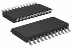
OP27GSZ: "S" indicates the SOIC (Surface Mount) package.
OP27AZ/883: Denotes military-grade ceramic packaging with full environmental testing.
2.3 Available Packages
| Package Type | Dimensions | Common Use Case |
|---|---|---|
| PDIP-8 | 9.27mm x 6.35mm | Prototyping and hand-soldering. |
| SOIC-8 | 4.9mm x 3.9mm | Standard machine-assembled PCBs. |
| TO-99 | Circular Metal Can | High-reliability/Military legacy systems. |
3. Design & Integration Guide (For Engineers & Makers)
Pro Tip: Always verify pin compatibility before migrating from older series like the OP07. While pinouts are often the same, the OP27's higher speed may require better decoupling.
3.1 Hardware Implementation
Bypass Capacitors: To maintain stability and low noise, place a 0.1 µF ceramic capacitor in parallel with a 10 µF tantalum capacitor as close to the V+ and V- pins as possible.
PCB Layout: Use a solid ground plane. Keep input traces short to minimize EMI pickup, which can negate the benefits of the ultra-low noise floor.
Thermal Management: Under standard ±15V operation, the OP27 consumes roughly 3-5mA. Heatsinks are generally unnecessary, but ensure the chip is not placed near high-heat components like power transistors.
3.2 Common Design Challenges
Issue: Not Rail-to-Rail: The OP27 cannot reach the supply rails. It requires roughly 2V of headroom.
Fix: If using a ±15V supply, limit your output signal to ±13V. For 5V-only systems, consider a modern RRIO part like the ADA4075.
Issue: Minimum Supply Voltage: The OP27 will fail in 3.3V or 5V single-supply systems.
Fix: Ensure your power rail provides at least ±4V (8V total span).
4. Typical Applications & Use Cases
📺 Video Recommendation: OP27 Guide
4.1 Real-World Example: Microphone Preamplifier
In professional audio recording, the OP27 is used as a Microphone Preamplifier. Because microphones produce very small voltages, the 3 nV/√Hz noise spec of the OP27 ensures that the "hiss" is kept below the audible threshold, while the 8 MHz bandwidth ensures high-fidelity reproduction of the entire audio spectrum.

5. Alternatives and Cross-Reference Guide
If the OP27 is unavailable or doesn't meet specific power constraints, consider these:
Direct Replacements: OPA27 (Texas Instruments version) is a pin-to-pin compatible alternative.
Better Performance: AD797 offers even lower noise (0.9 nV/√Hz) for extreme precision requirements.
Cost-Effective/Audio: NE5534 is a budget-friendly option for audio, though it lacks the DC precision (higher offset) of the OP27.
High Speed: OP37 is similar but decompensated for higher speeds (stable at gains >5).
6. Frequently Asked Questions (FAQ)
Q: What is the difference between OP27 and OP37?
A: The OP27 is unity-gain stable, whereas the OP37 is decompensated for higher speed (slew rate of 17 V/µs) but is only stable at gains of 5 or higher.
Q: Can OP27 be used in battery-operated devices?
A: Only if the battery provides at least ±4V. Due to its ~4mA quiescent current, it is not considered a "low-power" op-amp by modern standards.
Q: Where can I find the OP27 datasheet and library files?
A: Official datasheets are hosted on the Analog Devices website. CAD symbols are available via Ultra Librarian or SnapEDA for most major ECAD tools.
7. Datasheets & Resources
Official Datasheet: Analog Devices OP27 Series
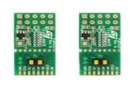
Development Tools: Evaluation boards for standard 8-pin SOIC op-amps can be used for rapid prototyping.
Specifications
 A Comprehensive Guide to Tamura 2DM150806CM Gate Driver
11 March 20241022
 IRF9640 P-Channel MOSFET: Pinout, Datasheet, Equivalent, and Circuit
01 September 20217698
![CR123A VS. RCR123A: Are They Interchangeable? [FAQ & Video]](https://res.utmel.com/Images/Article/01bb2481-28f2-4c64-8e83-1e5d54f739fe.jpg) CR123A VS. RCR123A: Are They Interchangeable? [FAQ & Video]
CR123A VS. RCR123A: Are They Interchangeable? [FAQ & Video]24 August 20229737
 SCC2691 Universal Asynchronous Receiver/Transmitter: Pinout, Equivalent and Datasheet
15 April 20221167
 Renesas R5F5630BCDFC Microcontroller: A Technical Overview
29 February 2024197
 SN74LVC1G08DCKR positive-AND gate: Features, Applications and Datasheet
20 October 2023917
 KSZ8895MQXI Ethernet Switch SPI Interface 128-PQFP: Datasheet, Pinout, and equivalent
11 February 20221779
 VL53L1X Laser-Ranging Sensor: Datasheet, Pinout and Schematic
29 July 202110820
 What is a Cascode Amplifier?
27 March 202513229
 Detecting Wafer Patterns using Semi-Supervised Learning
21 October 20221212
 Foxconn Announces Investment of $9 Billion to Build a Chip Factory in Saudi Arabia
15 March 20225285
 Introduction to TRIAC and TRIAC Dimmer
10 September 20209381
 DIP Switch: Introduction and Classification
20 January 202112809
 New Crisis in Semiconductors: Neon Gas Prices Soar 9 Times
21 March 20226203
 Memory ICs: Types, Applications & Selection (2025)
30 April 20252838
 Semiconductor Material Industry Guide
21 January 20225764
In Stock
United States
China
Canada
Japan
Russia
Germany
United Kingdom
Singapore
Italy
Hong Kong(China)
Taiwan(China)
France
Korea
Mexico
Netherlands
Malaysia
Austria
Spain
Switzerland
Poland
Thailand
Vietnam
India
United Arab Emirates
Afghanistan
Åland Islands
Albania
Algeria
American Samoa
Andorra
Angola
Anguilla
Antigua & Barbuda
Argentina
Armenia
Aruba
Australia
Azerbaijan
Bahamas
Bahrain
Bangladesh
Barbados
Belarus
Belgium
Belize
Benin
Bermuda
Bhutan
Bolivia
Bonaire, Sint Eustatius and Saba
Bosnia & Herzegovina
Botswana
Brazil
British Indian Ocean Territory
British Virgin Islands
Brunei
Bulgaria
Burkina Faso
Burundi
Cabo Verde
Cambodia
Cameroon
Cayman Islands
Central African Republic
Chad
Chile
Christmas Island
Cocos (Keeling) Islands
Colombia
Comoros
Congo
Congo (DRC)
Cook Islands
Costa Rica
Côte d’Ivoire
Croatia
Cuba
Curaçao
Cyprus
Czechia
Denmark
Djibouti
Dominica
Dominican Republic
Ecuador
Egypt
El Salvador
Equatorial Guinea
Eritrea
Estonia
Eswatini
Ethiopia
Falkland Islands
Faroe Islands
Fiji
Finland
French Guiana
French Polynesia
Gabon
Gambia
Georgia
Ghana
Gibraltar
Greece
Greenland
Grenada
Guadeloupe
Guam
Guatemala
Guernsey
Guinea
Guinea-Bissau
Guyana
Haiti
Honduras
Hungary
Iceland
Indonesia
Iran
Iraq
Ireland
Isle of Man
Israel
Jamaica
Jersey
Jordan
Kazakhstan
Kenya
Kiribati
Kosovo
Kuwait
Kyrgyzstan
Laos
Latvia
Lebanon
Lesotho
Liberia
Libya
Liechtenstein
Lithuania
Luxembourg
Macao(China)
Madagascar
Malawi
Maldives
Mali
Malta
Marshall Islands
Martinique
Mauritania
Mauritius
Mayotte
Micronesia
Moldova
Monaco
Mongolia
Montenegro
Montserrat
Morocco
Mozambique
Myanmar
Namibia
Nauru
Nepal
New Caledonia
New Zealand
Nicaragua
Niger
Nigeria
Niue
Norfolk Island
North Korea
North Macedonia
Northern Mariana Islands
Norway
Oman
Pakistan
Palau
Palestinian Authority
Panama
Papua New Guinea
Paraguay
Peru
Philippines
Pitcairn Islands
Portugal
Puerto Rico
Qatar
Réunion
Romania
Rwanda
Samoa
San Marino
São Tomé & Príncipe
Saudi Arabia
Senegal
Serbia
Seychelles
Sierra Leone
Sint Maarten
Slovakia
Slovenia
Solomon Islands
Somalia
South Africa
South Sudan
Sri Lanka
St Helena, Ascension, Tristan da Cunha
St. Barthélemy
St. Kitts & Nevis
St. Lucia
St. Martin
St. Pierre & Miquelon
St. Vincent & Grenadines
Sudan
Suriname
Svalbard & Jan Mayen
Sweden
Syria
Tajikistan
Tanzania
Timor-Leste
Togo
Tokelau
Tonga
Trinidad & Tobago
Tunisia
Turkey
Turkmenistan
Turks & Caicos Islands
Tuvalu
U.S. Outlying Islands
U.S. Virgin Islands
Uganda
Ukraine
Uruguay
Uzbekistan
Vanuatu
Vatican City
Venezuela
Wallis & Futuna
Yemen
Zambia
Zimbabwe