
 Product
 Brand
Brand Articles
 Tools
Tools
SB330 Schottky Barrier Rectifier: Package, Pinout, and Datasheet

Schottky Diode Rectifier Fast Recovery =< 500ns, > 200mA (Io) 500mV @ 3A -65°C~125°C 500μA @ 30V 2-Termination Tape & Reel (TR) DO-201AD, Axial Through Hole
Unit Price: $0.621227
Ext Price: $0.62


Schottky Diode Rectifier Fast Recovery =< 500ns, > 200mA (Io) 500mV @ 3A -65°C~125°C 500μA @ 30V 2-Termination Tape & Reel (TR) DO-201AD, Axial Through Hole
The SB330 is a Schottky Barrier Rectifier. This article mainly introduces Package, Pinout, Datasheet and other detailed information about ON Semiconductor SB330.

What is a schottky diode?
SB330 Description
The SB330 is a Schottky Barrier Rectifier for use in low voltage high-frequency inverters, freewheeling, dc-to-dc converters, and polarity protection applications.
SB330 Pinout
The SB330 Pinout is shown as follows.

Pinout
Primary Characteristics
| IF(AV) | 3.0 A |
| VRRM | 20 V to 60 V |
| IFSM | 120 A |
| VF | 0.49 V, 0.68 V |
| TJ max | 125 °C, 150 °C |
SB330 CAD Model
The following figure is SB330 CAD Model.

Symbol

Footprint

3D Model
SB330 Features
• Guard Ring Die Construction for Transient Protection
• Low Power Loss, High Efficiency
• High Surge Capability
• High Current Capability and Low Forward Voltage Drop
• Surge Overload Rating to 80A Peak
• For Use in Low Voltage, High Frequency Inverters, Free Wheeling, and Polarity Protection Applications
• IEC 61000-4-2 (ESD - 150pF/330Ω) Contact - ±15kV
• Lead-Free Finish; RoHS Compliant
• For automotive applications requiring specific change control
(i.e. parts qualified to AEC-Q100/101/200, PPAP capable, and manufactured in IATF 16949 certified facilities)
Specifications
- TypeParameter
- Lifecycle Status
Lifecycle Status refers to the current stage of an electronic component in its product life cycle, indicating whether it is active, obsolete, or transitioning between these states. An active status means the component is in production and available for purchase. An obsolete status indicates that the component is no longer being manufactured or supported, and manufacturers typically provide a limited time frame for support. Understanding the lifecycle status is crucial for design engineers to ensure continuity and reliability in their projects.
ACTIVE (Last Updated: 4 days ago) - Factory Lead Time13 Weeks
- Mount
In electronic components, the term "Mount" typically refers to the method or process of physically attaching or fixing a component onto a circuit board or other electronic device. This can involve soldering, adhesive bonding, or other techniques to secure the component in place. The mounting process is crucial for ensuring proper electrical connections and mechanical stability within the electronic system. Different components may have specific mounting requirements based on their size, shape, and function, and manufacturers provide guidelines for proper mounting procedures to ensure optimal performance and reliability of the electronic device.
Through Hole - Mounting Type
The "Mounting Type" in electronic components refers to the method used to attach or connect a component to a circuit board or other substrate, such as through-hole, surface-mount, or panel mount.
Through Hole - Package / Case
refers to the protective housing that encases an electronic component, providing mechanical support, electrical connections, and thermal management.
DO-201AD, Axial - Number of Pins2
- Weight360mg
- Diode Element Material
The parameter "Diode Element Material" refers to the specific semiconductor material used in the construction of a diode. This material determines the electrical characteristics and performance of the diode, including its forward voltage drop, reverse breakdown voltage, and switching speed. Common diode element materials include silicon, germanium, and gallium arsenide, each offering different advantages for various applications. The choice of material impacts the diode's efficiency, thermal stability, and overall suitability for specific electronic circuits.
SILICON - Number of Elements1
- Power Dissipation (Max)3.6W
- Packaging
Semiconductor package is a carrier / shell used to contain and cover one or more semiconductor components or integrated circuits. The material of the shell can be metal, plastic, glass or ceramic.
Tape & Reel (TR) - Published2013
- JESD-609 Code
The "JESD-609 Code" in electronic components refers to a standardized marking code that indicates the lead-free solder composition and finish of electronic components for compliance with environmental regulations.
e3 - Pbfree Code
The "Pbfree Code" parameter in electronic components refers to the code or marking used to indicate that the component is lead-free. Lead (Pb) is a toxic substance that has been widely used in electronic components for many years, but due to environmental concerns, there has been a shift towards lead-free alternatives. The Pbfree Code helps manufacturers and users easily identify components that do not contain lead, ensuring compliance with regulations and promoting environmentally friendly practices. It is important to pay attention to the Pbfree Code when selecting electronic components to ensure they meet the necessary requirements for lead-free applications.
yes - Part Status
Parts can have many statuses as they progress through the configuration, analysis, review, and approval stages.
Active - Moisture Sensitivity Level (MSL)
Moisture Sensitivity Level (MSL) is a standardized rating that indicates the susceptibility of electronic components, particularly semiconductors, to moisture-induced damage during storage and the soldering process, defining the allowable exposure time to ambient conditions before they require special handling or baking to prevent failures
1 (Unlimited) - Number of Terminations2
- ECCN Code
An ECCN (Export Control Classification Number) is an alphanumeric code used by the U.S. Bureau of Industry and Security to identify and categorize electronic components and other dual-use items that may require an export license based on their technical characteristics and potential for military use.
EAR99 - Terminal Finish
Terminal Finish refers to the surface treatment applied to the terminals or leads of electronic components to enhance their performance and longevity. It can improve solderability, corrosion resistance, and overall reliability of the connection in electronic assemblies. Common finishes include nickel, gold, and tin, each possessing distinct properties suitable for various applications. The choice of terminal finish can significantly impact the durability and effectiveness of electronic devices.
Tin (Sn) - Max Operating Temperature
The Maximum Operating Temperature is the maximum body temperature at which the thermistor is designed to operate for extended periods of time with acceptable stability of its electrical characteristics.
125°C - Min Operating Temperature
The "Min Operating Temperature" parameter in electronic components refers to the lowest temperature at which the component is designed to operate effectively and reliably. This parameter is crucial for ensuring the proper functioning and longevity of the component, as operating below this temperature may lead to performance issues or even damage. Manufacturers specify the minimum operating temperature to provide guidance to users on the environmental conditions in which the component can safely operate. It is important to adhere to this parameter to prevent malfunctions and ensure the overall reliability of the electronic system.
-65°C - Applications
The parameter "Applications" in electronic components refers to the specific uses or functions for which a component is designed. It encompasses various fields such as consumer electronics, industrial automation, telecommunications, automotive, and medical devices. Understanding the applications helps in selecting the right components for a particular design based on performance, reliability, and compatibility requirements. This parameter also guides manufacturers in targeting their products to relevant markets and customer needs.
GENERAL PURPOSE - Additional Feature
Any Feature, including a modified Existing Feature, that is not an Existing Feature.
FREE WHEELING DIODE - HTS Code
HTS (Harmonized Tariff Schedule) codes are product classification codes between 8-1 digits. The first six digits are an HS code, and the countries of import assign the subsequent digits to provide additional classification. U.S. HTS codes are 1 digits and are administered by the U.S. International Trade Commission.
8541.10.00.80 - Voltage - Rated DC
Voltage - Rated DC is a parameter that specifies the maximum direct current (DC) voltage that an electronic component can safely handle without being damaged. This rating is crucial for ensuring the proper functioning and longevity of the component in a circuit. Exceeding the rated DC voltage can lead to overheating, breakdown, or even permanent damage to the component. It is important to carefully consider this parameter when designing or selecting components for a circuit to prevent any potential issues related to voltage overload.
30V - Terminal Form
Occurring at or forming the end of a series, succession, or the like; closing; concluding.
WIRE - Current Rating
Current rating is the maximum current that a fuse will carry for an indefinite period without too much deterioration of the fuse element.
3A - Base Part Number
The "Base Part Number" (BPN) in electronic components serves a similar purpose to the "Base Product Number." It refers to the primary identifier for a component that captures the essential characteristics shared by a group of similar components. The BPN provides a fundamental way to reference a family or series of components without specifying all the variations and specific details.
SB330 - Polarity
In electronic components, polarity refers to the orientation or direction in which the component must be connected in a circuit to function properly. Components such as diodes, capacitors, and LEDs have polarity markings to indicate which terminal should be connected to the positive or negative side of the circuit. Connecting a component with incorrect polarity can lead to malfunction or damage. It is important to pay attention to polarity markings and follow the manufacturer's instructions to ensure proper operation of electronic components.
Standard - Element Configuration
The distribution of electrons of an atom or molecule (or other physical structure) in atomic or molecular orbitals.
Single - Speed
In electronic components, "Speed" typically refers to the rate at which data can be processed or transferred within the component. It is a measure of how quickly the component can perform its functions, such as executing instructions or transmitting signals. Speed is often specified in terms of frequency, such as clock speed in processors or data transfer rate in memory modules. Higher speed components can perform tasks more quickly, leading to improved overall performance in electronic devices. It is an important parameter to consider when designing or selecting electronic components for specific applications.
Fast Recovery =< 500ns, > 200mA (Io) - Diode Type
In electronic components, the parameter "Diode Type" refers to the specific type or configuration of a diode, which is a semiconductor device that allows current to flow in one direction only. There are various types of diodes, each designed for specific applications and functions. Common diode types include rectifier diodes, zener diodes, light-emitting diodes (LEDs), and Schottky diodes, among others. The diode type determines the diode's characteristics, such as forward voltage drop, reverse breakdown voltage, and maximum current rating, making it crucial for selecting the right diode for a particular circuit or application. Understanding the diode type is essential for ensuring proper functionality and performance in electronic circuits.
Schottky - Current - Reverse Leakage @ Vr
Current - Reverse Leakage @ Vr is a parameter that describes the amount of current that flows in the reverse direction through a diode or other semiconductor component when a reverse voltage (Vr) is applied across it. This leakage current is typically very small, but it is important to consider in electronic circuits as it can affect the overall performance and reliability of the component. The reverse leakage current is influenced by factors such as the material properties of the semiconductor, temperature, and the magnitude of the reverse voltage applied. Manufacturers provide this parameter in datasheets to help engineers and designers understand the behavior of the component in reverse bias conditions.
500μA @ 30V - Output Current
The rated output current is the maximum load current that a power supply can provide at a specified ambient temperature. A power supply can never provide more current that it's rated output current unless there is a fault, such as short circuit at the load.
3A - Voltage - Forward (Vf) (Max) @ If
The parameter "Voltage - Forward (Vf) (Max) @ If" refers to the maximum voltage drop across a diode when it is forward-biased and conducting a specified forward current (If). It indicates the maximum potential difference the diode can withstand while allowing current to flow in the forward direction without breaking down. This value is crucial for designing circuits as it helps determine how much voltage will be lost across the diode during operation. Higher Vf values can lead to reduced efficiency in power applications, making this parameter essential for optimizing circuit performance.
500mV @ 3A - Case Connection
Case Connection refers to the method by which an electronic component's case or housing is connected to the electrical circuit. This connection is important for grounding purposes, mechanical stability, and heat dissipation. The case connection can vary depending on the type of component and its intended application. It is crucial to ensure a secure and reliable case connection to maintain the overall performance and safety of the electronic device.
ISOLATED - Forward Current
Current which flows upon application of forward voltage.
3A - Max Reverse Leakage Current
Max Reverse Leakage Current refers to the maximum amount of current that can flow through a semiconductor device, such as a diode or transistor, when it is reverse biased. This current is an important parameter as it indicates the level of unintended current that can flow when the device is not conducting in the forward direction. High values of reverse leakage current can lead to power loss, reduced efficiency, and may affect the performance and reliability of electronic circuits. It is particularly critical in applications where precise current control and low power consumption are necessary.
500μA - Operating Temperature - Junction
Operating Temperature - Junction refers to the maximum temperature at which the junction of an electronic component can safely operate without causing damage or performance degradation. This parameter is crucial for determining the reliability and longevity of the component, as excessive heat can lead to thermal stress and failure. Manufacturers specify the operating temperature range to ensure that the component functions within safe limits under normal operating conditions. It is important for designers and engineers to consider the operating temperature - junction when selecting and using electronic components to prevent overheating and ensure optimal performance.
-65°C~125°C - Max Surge Current
Surge current is a peak non repetitive current. Maximum (peak or surge) forward current = IFSM or if(surge), the maximum peak amount of current the diode is able to conduct in forward bias mode.
80A - Forward Voltage
the amount of voltage needed to get current to flow across a diode.
500mV - Max Reverse Voltage (DC)
Max Reverse Voltage (DC) refers to the maximum voltage that a semiconductor device, such as a diode, can withstand in the reverse bias direction without failing. Exceeding this voltage can lead to breakdown and potential damage to the component. It is a critical parameter in circuit design to ensure reliability and prevent failure when the device is subjected to reverse voltage conditions.
30V - Average Rectified Current
Mainly used to characterize alternating voltage and current. It can be computed by averaging the absolute value of a waveform over one full period of the waveform.
3A - Number of Phases1
- Peak Reverse Current
The maximum voltage that a diode can withstand in the reverse direction without breaking down or avalanching.If this voltage is exceeded the diode may be destroyed. Diodes must have a peak inverse voltage rating that is higher than the maximum voltage that will be applied to them in a given application.
500μA - Max Repetitive Reverse Voltage (Vrrm)
The Max Repetitive Reverse Voltage (Vrrm) is a crucial parameter in electronic components, particularly in diodes and transistors. It refers to the maximum voltage that can be applied across the component in the reverse direction without causing damage. This parameter is important for ensuring the proper functioning and longevity of the component in circuits where reverse voltage may be present. Exceeding the Vrrm rating can lead to breakdown and failure of the component, so it is essential to carefully consider this specification when designing or selecting components for a circuit.
30V - Capacitance @ Vr, F
Capacitance @ Vr, F refers to the capacitance value of a capacitor measured at a specified rated voltage (Vr). It indicates how much electrical charge the capacitor can store per volt when subjected to this voltage. This parameter is essential for understanding the behavior of capacitors in circuits, particularly under different voltage conditions, and ensures that the component operates within its safe limits. The unit of measurement is Farads (F), which quantifies the capacitor's ability to hold an electrical charge.
180pF @ 4V 1MHz - Peak Non-Repetitive Surge Current
Peak Non-Repetitive Surge Current is a specification in electronic components that refers to the maximum current that the component can withstand for a short duration without sustaining damage. This surge current typically occurs as a result of sudden voltage spikes or transient events in the circuit. It is important to consider this parameter when designing or selecting components to ensure they can handle occasional high-current surges without failing. The value of Peak Non-Repetitive Surge Current is usually specified in amperes and is crucial for protecting the component and maintaining the overall reliability of the circuit.
80A - Max Forward Surge Current (Ifsm)
Max Forward Surge Current (Ifsm) is a parameter used to specify the maximum peak current that a diode or other electronic component can withstand for a short duration during a surge event. Surge currents can occur due to sudden changes in voltage or power supply fluctuations, and the Ifsm rating helps determine the component's ability to handle such transient overloads without being damaged. It is important to consider the Ifsm rating when selecting components for applications where surge currents are expected, such as in power supplies, motor drives, and other high-power circuits. Exceeding the Ifsm rating can lead to overheating, degradation, or failure of the component, so it is crucial to ensure that the chosen component can safely handle the expected surge currents in the circuit.
80A - Natural Thermal Resistance
Natural thermal resistance in electronic components refers to the ability of a device to dissipate heat without the assistance of external cooling methods such as fans or liquid cooling. It is a measure of how effectively a component can transfer heat from its junction to its surrounding environment through natural convection and radiation. This parameter is critical for assessing the thermal performance and reliability of electronic devices, as excessive heat can lead to failure or diminished efficiency. Natural thermal resistance is typically expressed in degrees Celsius per watt (°C/W) and is influenced by factors such as the material properties, component design, and ambient conditions.
40 °C/W - REACH SVHC
The parameter "REACH SVHC" in electronic components refers to the compliance with the Registration, Evaluation, Authorization, and Restriction of Chemicals (REACH) regulation regarding Substances of Very High Concern (SVHC). SVHCs are substances that may have serious effects on human health or the environment, and their use is regulated under REACH to ensure their safe handling and minimize their impact.Manufacturers of electronic components need to declare if their products contain any SVHCs above a certain threshold concentration and provide information on the safe use of these substances. This information allows customers to make informed decisions about the potential risks associated with using the components and take appropriate measures to mitigate any hazards.Ensuring compliance with REACH SVHC requirements is essential for electronics manufacturers to meet regulatory standards, protect human health and the environment, and maintain transparency in their supply chain. It also demonstrates a commitment to sustainability and responsible manufacturing practices in the electronics industry.
No SVHC - Radiation Hardening
Radiation hardening is the process of making electronic components and circuits resistant to damage or malfunction caused by high levels of ionizing radiation, especially for environments in outer space (especially beyond the low Earth orbit), around nuclear reactors and particle accelerators, or during nuclear accidents or nuclear warfare.
No - RoHS Status
RoHS means “Restriction of Certain Hazardous Substances” in the “Hazardous Substances Directive” in electrical and electronic equipment.
ROHS3 Compliant - Lead Free
Lead Free is a term used to describe electronic components that do not contain lead as part of their composition. Lead is a toxic material that can have harmful effects on human health and the environment, so the electronics industry has been moving towards lead-free components to reduce these risks. Lead-free components are typically made using alternative materials such as silver, copper, and tin. Manufacturers must comply with regulations such as the Restriction of Hazardous Substances (RoHS) directive to ensure that their products are lead-free and environmentally friendly.
Lead Free
Parts with Similar Specs
- ImagePart NumberManufacturerMountForward VoltageForward CurrentMax Reverse Leakage CurrentWeightNumber of PinsOperating Temperature - JunctionPackage / CaseView Compare
![SB330]()
SB330
Through Hole
500 mV
3 A
500 μA
360 mg
2
-65°C ~ 125°C
DO-201AD, Axial
![1N5822]()
Through Hole
525 mV
3 A
500 μA
360 mg
2
-65°C ~ 125°C
DO-201AD, Axial
![SB340]()
Through Hole
500 mV
3 A
500 μA
360 mg
2
-65°C ~ 125°C
DO-201AD, Axial
![SB320]()
Through Hole
500 mV
3 A
500 μA
360 mg
2
-65°C ~ 125°C
DO-201AD, Axial

SB330 Alternatives
| Part Number | Description | Manufacturer |
| SR303-T/RDIODES | Rectifier Diode, Schottky, 1 Phase, 1 Element, 3A, Silicon, | Frontier Electronics Co Ltd |
| SB330-E3/54DIODES | DIODE 3 A, 30 V, SILICON, RECTIFIER DIODE, DO-201AD, ROHS COMPLIANT, PLASTIC PACKAGE-2, Rectifier Diode | Vishay Semiconductors |
| SB330-T/RDIODES | Rectifier Diode, Schottky, 1 Phase, 1 Element, 3A, Silicon, | Frontier Electronics Co Ltd |
| SB330A-E3DIODES | DIODE 3 A, 30 V, SILICON, RECTIFIER DIODE, DO-201AD, LEAD FREE, PLASTIC PACKAGE-2, Rectifier Diode | Vishay Semiconductors |
| SR303DIODES | Rectifier Diode | Cheng-Yi Electronic Co Ltd |
| SB330EDIODES | Rectifier Diode, Schottky, 1 Phase, 1 Element, 3A, 30V V(RRM), Silicon, DO-201AD, PLASTIC PACKAGE-2 | Promax-Johnton Electronic Corporation |
| SB330-E3DIODES | DIODE 3 A, 30 V, SILICON, RECTIFIER DIODE, DO-201AD, LEAD FREE, PLASTIC PACKAGE-2, Rectifier Diode | Vishay Semiconductors |
| SB330-E3/73DIODES | DIODE 3 A, 30 V, SILICON, RECTIFIER DIODE, DO-201AD, ROHS COMPLIANT, PLASTIC PACKAGE-2, Rectifier Diode | Vishay Semiconductors |
| SB330A-E3/54DIODES | Rectifier Diode, Schottky, 1 Phase, 1 Element, 3A, 30V V(RRM), Silicon, DO-201AD, ROHS COMPLIANT, PLASTIC PACKAGE-2 | Vishay Semiconductors |
| SR303-TDIODES | Rectifier Diode, Schottky, 1 Phase, 1 Element, 3A, 30V V(RRM), Silicon, DO-201AD, PLASTIC PACKAGE-2 | Diodes Incorporated |
SB330 Applications
• Low Voltage High-Frequency Inverters
• Freewheeling
• Dc-to-dc Converters
• Polarity Protection Applications
SB330 Package
The following is SB330 Package.

Package
SB330 Manufacturer
ON Semiconductor (Nasdaq: ON) is a leader in energy-efficient technology, enabling customers to cut worldwide energy consumption. In the automotive, communications, computing, consumer, industrial, LED lighting, medical, military/aerospace, and power supply markets, the company offers a comprehensive portfolio of energy efficient power and signal management, logic, discrete, and custom solutions to help design engineers solve their unique design challenges. ON Semiconductor has a world-class supply chain and quality program, as well as a network of manufacturing sites, sales offices, and design centers in important markets in North America, Europe, and Asia Pacific.
Trend Analysis
Datasheet PDF
- Datasheets :
- Environmental Information :
- PCN Design/Specification :
- PCN Packaging :
What is Schottky barrier rectifier?
Schottky Barrier Rectifiers Working and Its Applications. The Schottky diode or Schottky Barrier Rectifier is named after the German physicist “Walter H. Schottky”, which is a semiconductor diode designed with metal by the semiconductor junction. It has a low-forward voltage drop and a very rapid switching act.
What is the use of Schottky barrier diode?
Schottky diodes are used for their low turn-on voltage, fast recovery time, and low-loss energy at higher frequencies. These characteristics make Schottky diodes capable of rectifying a current by facilitating a quick transition from conducting to blocking state.
How does a Schottky rectifier work?
In a Schottky diode, a semiconductor–metal junction is formed between a semiconductor and a metal, thus creating a Schottky barrier. The N-type semiconductor acts as the cathode and the metal side acts as the anode of the diode. This Schottky barrier results in both a low forward voltage drop and very fast switching.
How do you test a Schottky barrier rectifier?
Connecting the red positive test leads to the anode of the Schottky diode and the black common test leads to the cathode of the diode. Listen for a “beep” or a “buzz” from the multimeter. If the Schottky diode responds as expected, the multimeter will sound a tone.
 2SK170 N-Channel MOSFET Transistor: Replacement, Equivalent and Datasheet pdf
06 January 20224928
 MIC2775 Micro-Power Voltage Supervisor: Pinout, Equivalent and Datasheet
12 April 20221391
 LM5164QDDARQ1: LM5164, Converter, 48V, 100V Input
16 August 20245308
 IRF610 Power MOSFET: Equivalent, Pinout and Datasheet
01 September 20213215
 10M16DAU324I6G FPGA Device: Features, Specifications, Advantages
14 August 2024890
 2N4400 Transistor: Datasheet, Pinout, Equivalents
12 October 20212303
 IRFP9240 Power MOSFET : Datasheet, Pinout and Equivalent
26 August 20217329
 Unraveling the Zilog ZNEO™ Z16F Series Microcontroller: A Comprehensive Technical Analysis
29 February 2024414
 All About Video Connectors and Their Uses in Today’s Technology
02 July 20252586
 Comprehensive Analysis of Each Functional Circuit of Switching Power Supply
06 May 20225165
 What is Variable Frequency Driver(VFD)?
20 October 20212537
 What is Network Topology?
23 December 20213764
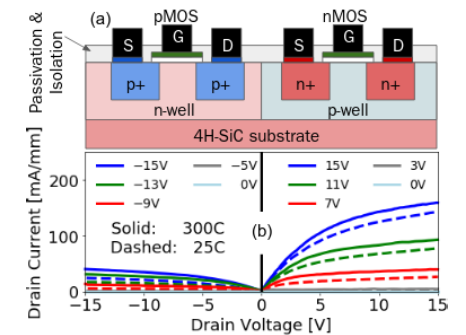 Advanced CMOS Devices with Wide Bandgap and Ultrawide Bandgap Technologies
15 March 20243108
 Can ARM challenge X86 in the field of PC chips?
06 June 20225525
 Basic Introduction to Memristor
12 January 202111733
 Getting Started with Arduino: What is Arduino and How to Use Arduino Boards
28 September 20236167
ON Semiconductor
In Stock: 2304
Minimum: 1 Multiples: 1
Qty
Unit Price
Ext Price
1
$0.621227
$0.62
10
$0.586063
$5.86
100
$0.552890
$55.29
500
$0.521594
$260.80
1000
$0.492070
$492.07
Not the price you want? Send RFQ Now and we'll contact you ASAP.
Inquire for More Quantity
![RB521S30T1G]() RB521S30T1G
RB521S30T1GON Semiconductor
![MBRS130T3]() MBRS130T3
MBRS130T3ON Semiconductor
![MBRS3100T3G]() MBRS3100T3G
MBRS3100T3GON Semiconductor
![MMSD4148T1G]() MMSD4148T1G
MMSD4148T1GON Semiconductor
![1N4148WT]() 1N4148WT
1N4148WTON Semiconductor
![1N914BWS]() 1N914BWS
1N914BWSON Semiconductor
![RB751S40T1G]() RB751S40T1G
RB751S40T1GON Semiconductor
![1N4148WS]() 1N4148WS
1N4148WSON Semiconductor
![BAS16HT1G]() BAS16HT1G
BAS16HT1GON Semiconductor
![MBR0520LT1G]() MBR0520LT1G
MBR0520LT1GON Semiconductor


