

 Product
 Brand
Brand Articles
 Tools
Tools
SMBJ60CA TVs Diodes: System, Pinout, and Datasheet


TVS DIODE 60V 96.8V DO214AA
The SMBJ60CA is a Transient Voltage Suppression Diode. This article mainly introduces system, pinout, datasheet and other detailed information about Littelfuse Inc. SMBJ60CA.

How TVS Diodes work
SMBJ60CA Description
The SMBJ60CA was created to safeguard sensitive electronic equipment against voltage transients such as those caused by lightning and other transient voltage events.
The SMBJ series is designed to safeguard sensitive equipment from electrostatic discharges and electrical overstress according to IEC 61000-4-2 and MIL-STD 883 , method 3015, and IEC 61000-4-4 and 5. Surges of less than 600 W (10/1000 s) are more commonly encountered with this device. Planar technology allows it to be used in high-end equipment and SMPS where low leakage current and high junction temperature are required for long-term reliability and stability.
The SMBJ series comes in SMB packaging.
SMBJ60CA Pinout
The following figure is SMBJ60CA Pinout.
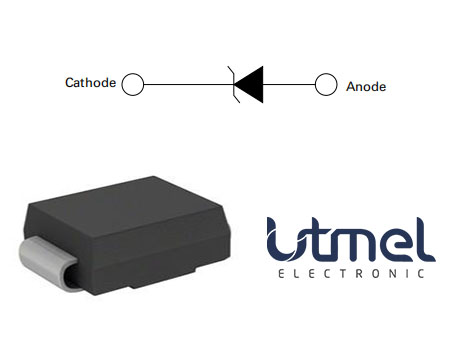
Pinout
SMBJ60CA CAD Model
The followings are SMBJ60CA Symbol, Footprint and 3D Model.

Symbol
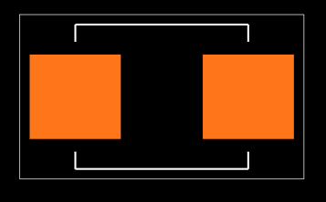
Footprint
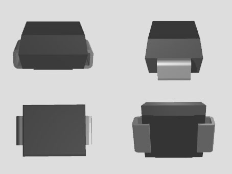
3D Model
SMBJ60CA Features
• 600W peak pulse power capability at 10/1000μs waveform, repetition rate (duty cycles):0.01%
• Excellent clamping capability
• Low incremental surge resistance
• Typical IR less than 1μA when VBR min>12V
• For surface mounted applications to optimize board space
• Low profile package
• Typical failure mode is a short circuit condition for current events exceeding the component rating
• Whisker test is conducted based on JEDEC
JESD201A per its table 4a and 4c
• IEC-61000-4-2 ESD 30kV(Air), 30kV (Contact)
• EFT protection of data lines in accordance with IEC 61000-4-4
• Built-in strain relief
• Fast response time: typically less than 1.0ps from 0V to BV min
• High temperature to reflow soldering guaranteed: 260°C/40sec
• VBR @ TJ= VBR@25°C x (1+αT x (TJ - 25))(αT:Temperature Coefficient, typical value is 0.1%)
• Plastic package is flammability rated V-0 per UL-94
• Meet MSL level1, per J-STD-020, lead-frame maximum peak of 260°C
• Matte tin lead–free plated
• Halogen-free and RoHS compliant
• Pb-free E3 means 2nd level interconnect is Pb-free and the terminal finish material is tin(Sn) (IPC/JEDEC J-STD-609A.01)
• Glass passivated junction
• Low incremental surge resistance, excellent clamping capability
• Very fast response time
• -55 to 150°C Operating temperature range
Specifications
- TypeParameter
- Factory Lead Time17 Weeks
- Mounting Type
The "Mounting Type" in electronic components refers to the method used to attach or connect a component to a circuit board or other substrate, such as through-hole, surface-mount, or panel mount.
Surface Mount - Package / Case
refers to the protective housing that encases an electronic component, providing mechanical support, electrical connections, and thermal management.
DO-214AA, SMB - Number of Pins2
- Supplier Device Package
The parameter "Supplier Device Package" in electronic components refers to the physical packaging or housing of the component as provided by the supplier. It specifies the form factor, dimensions, and layout of the component, which are crucial for compatibility and integration into electronic circuits and systems. The supplier device package information typically includes details such as the package type (e.g., DIP, SOP, QFN), number of pins, pitch, and overall size, allowing engineers and designers to select the appropriate component for their specific application requirements. Understanding the supplier device package is essential for proper component selection, placement, and soldering during the manufacturing process to ensure optimal performance and reliability of the electronic system.
DO-214AA (SMBJ) - Manufacturer Package Identifier
The Manufacturer Package Identifier is a unique code or label assigned by the manufacturer to identify a specific package or housing style of an electronic component. This identifier helps in distinguishing between different package types of the same component, such as integrated circuits, transistors, or diodes. It typically includes information about the package dimensions, lead configuration, and other physical characteristics of the component. The Manufacturer Package Identifier is crucial for ensuring compatibility and proper assembly of electronic components in various devices and circuits.
SMB J-Bend - Breakdown Voltage / V66.7V
- Operating Temperature
The operating temperature is the range of ambient temperature within which a power supply, or any other electrical equipment, operate in. This ranges from a minimum operating temperature, to a peak or maximum operating temperature, outside which, the power supply may fail.
-65°C~150°C TJ - Packaging
Semiconductor package is a carrier / shell used to contain and cover one or more semiconductor components or integrated circuits. The material of the shell can be metal, plastic, glass or ceramic.
Tape & Reel (TR) - Series
In electronic components, the "Series" refers to a group of products that share similar characteristics, designs, or functionalities, often produced by the same manufacturer. These components within a series typically have common specifications but may vary in terms of voltage, power, or packaging to meet different application needs. The series name helps identify and differentiate between various product lines within a manufacturer's catalog.
SMBJ - Published2009
- Part Status
Parts can have many statuses as they progress through the configuration, analysis, review, and approval stages.
Active - Moisture Sensitivity Level (MSL)
Moisture Sensitivity Level (MSL) is a standardized rating that indicates the susceptibility of electronic components, particularly semiconductors, to moisture-induced damage during storage and the soldering process, defining the allowable exposure time to ambient conditions before they require special handling or baking to prevent failures
1 (Unlimited) - TypeZener
- Max Operating Temperature
The Maximum Operating Temperature is the maximum body temperature at which the thermistor is designed to operate for extended periods of time with acceptable stability of its electrical characteristics.
150°C - Min Operating Temperature
The "Min Operating Temperature" parameter in electronic components refers to the lowest temperature at which the component is designed to operate effectively and reliably. This parameter is crucial for ensuring the proper functioning and longevity of the component, as operating below this temperature may lead to performance issues or even damage. Manufacturers specify the minimum operating temperature to provide guidance to users on the environmental conditions in which the component can safely operate. It is important to adhere to this parameter to prevent malfunctions and ensure the overall reliability of the electronic system.
-55°C - Applications
The parameter "Applications" in electronic components refers to the specific uses or functions for which a component is designed. It encompasses various fields such as consumer electronics, industrial automation, telecommunications, automotive, and medical devices. Understanding the applications helps in selecting the right components for a particular design based on performance, reliability, and compatibility requirements. This parameter also guides manufacturers in targeting their products to relevant markets and customer needs.
General Purpose - Power Rating
The "Power Rating" of an electronic component refers to the maximum amount of power that the component can handle or dissipate without being damaged. It is typically measured in watts and is an important specification to consider when designing or selecting components for a circuit. Exceeding the power rating of a component can lead to overheating, malfunction, or even permanent damage. It is crucial to ensure that the power rating of each component in a circuit is sufficient to handle the power levels expected during normal operation to maintain the reliability and longevity of the electronic system.
600W - Voltage - Rated DC
Voltage - Rated DC is a parameter that specifies the maximum direct current (DC) voltage that an electronic component can safely handle without being damaged. This rating is crucial for ensuring the proper functioning and longevity of the component in a circuit. Exceeding the rated DC voltage can lead to overheating, breakdown, or even permanent damage to the component. It is important to carefully consider this parameter when designing or selecting components for a circuit to prevent any potential issues related to voltage overload.
60V - Power Line Protection
During fault, the only circuit breaker closest to the fault point should be tripped. The operating time of relay associated with protection of line should be as minimum as possible in order to prevent unnecessary tripping of circuit breakers associated with other healthy parts of power system.
No - Voltage - Breakdown (Min)
Voltage - Breakdown (Min) is a parameter used to specify the minimum voltage level at which an electronic component, such as a diode or capacitor, will break down and allow current to flow through it uncontrollably. This breakdown voltage is a critical characteristic that determines the maximum voltage the component can withstand before failing. It is important to ensure that the applied voltage does not exceed this minimum breakdown voltage to prevent damage to the component and maintain proper functionality. Manufacturers provide this specification to help engineers and designers select components that are suitable for their intended applications and operating conditions.
66.7V - Power - Peak Pulse
Power - Peak Pulse refers to the maximum transient power level that an electronic component, such as a diode or a transzorber, can safely dissipate during a short-duration pulse. This parameter is critical in determining the component's ability to withstand voltage spikes or surges without failure. It is typically expressed in watts and is measured over a specific duration, usually in microseconds or nanoseconds, to reflect the component's performance under peak conditions. Understanding this parameter helps designers select appropriate components for applications where transient conditions are expected.
600W - Current - Peak Pulse (10/1000μs)
The parameter "Current - Peak Pulse (10/1000μs)" in electronic components refers to the maximum current that a device can handle during a transient overvoltage event with a specific waveform, typically a 10/1000μs pulse. This parameter is important for surge protection devices such as transient voltage suppressors (TVS) and varistors, as it indicates the device's ability to divert excess current away from sensitive components and protect them from damage. A higher peak pulse current rating signifies better surge protection capability, making the component more suitable for applications exposed to high-voltage transients or lightning strikes. Designers should carefully consider this parameter when selecting surge protection components to ensure reliable operation and protection of their electronic circuits.
6.2A - Voltage - Clamping (Max) @ Ipp
Voltage - Clamping (Max) @ Ipp refers to the maximum voltage that a component, such as a transient voltage suppressor or diode, can clamp when subjected to a specific peak current (Ipp). It indicates the upper limit of voltage that the component will allow to pass through, effectively protecting sensitive circuits from overvoltage conditions. This parameter is crucial for ensuring that devices are safeguarded against voltage spikes without being damaged. Designers use this specification to select appropriate components for overvoltage protection in their applications.
96.8V - Voltage - Reverse Standoff (Typ)
Voltage - Reverse Standoff (Typ) refers to the maximum reverse voltage that a semiconductor device, such as a diode or a transient voltage suppressor, can withstand without entering into breakdown. It is typically specified as a nominal value and indicates the voltage level at which the device transitions from its non-conducting state to a conducting state when reverse-biased. Exceeding this voltage can lead to permanent damage or failure of the component. This parameter is crucial for ensuring the safe operating limits of electronic circuits, particularly in protecting sensitive components from voltage spikes.
60V - Bidirectional Channels
Bidirectional channels in electronic components refer to pathways or connections that allow signal transmission in both directions. This means that data can flow from one device to another and back again, enabling two-way communication. Such channels are essential in applications like data buses, communication interfaces, and certain types of network protocols, facilitating efficient and dynamic interactions between components.
1 - RoHS Status
RoHS means “Restriction of Certain Hazardous Substances” in the “Hazardous Substances Directive” in electrical and electronic equipment.
ROHS3 Compliant - Lead Free
Lead Free is a term used to describe electronic components that do not contain lead as part of their composition. Lead is a toxic material that can have harmful effects on human health and the environment, so the electronics industry has been moving towards lead-free components to reduce these risks. Lead-free components are typically made using alternative materials such as silver, copper, and tin. Manufacturers must comply with regulations such as the Restriction of Hazardous Substances (RoHS) directive to ensure that their products are lead-free and environmentally friendly.
Lead Free
SMBJ60CA Part Numbering System
The following shows SMBJ60CA Part Numbering System.
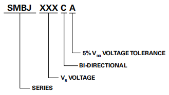
Part Numbering System
SMBJ60CA Part Marking System
The following figure is SMBJ60CA Part Marking System.
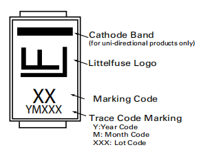
Part Marking System
SMBJ60CA Functional Diagram
The following figure is SMBJ60CA Functional Diagram.
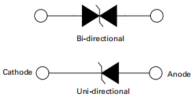
Functional Diagram
SMBJ60CA Alternatives
| Part Number | Description | Manufacturer |
| 1SMB60CADIODES | 600W, BIDIRECTIONAL, SILICON, TVS DIODE, CASE 403A-03, SMB, 2 PIN | Motorola Mobility LLC |
| SMBJ60CAHM4DIODES | Trans Voltage Suppressor Diode, 600W, 60V V(RWM), Bidirectional, 1 Element, Silicon, DO-214AA, ROHS COMPLIANT, PLASTIC, SMB, 2 PIN | Taiwan Semiconductor |
| SMBJ60CA-5B-E3DIODES | DIODE 600 W, BIDIRECTIONAL, SILICON, TVS DIODE, DO-214AA, PLASTIC, SMB, 2 PIN, Transient Suppressor | Vishay Semiconductors |
| SMBJ60CA/TR13DIODES | Trans Voltage Suppressor Diode, | YAGEO Corporation |
| SMBJ60CHR5GDIODES | Trans Voltage Suppressor Diode, 600W, 60V V(RWM), Bidirectional, 1 Element, Silicon, DO-214AA, SMB, 2 PIN | Taiwan Semiconductor |
| P6SMBJ60CADIODES | Trans Voltage Suppressor Diode, 600W, 60V V(RWM), Bidirectional, 1 Element, Silicon, DO-214AA, PLASTIC, SMB, 2 PIN | SEMIKRON |
| P6SMBJ60CATRFDIODES | Trans Voltage Suppressor Diode, 600W, 60V V(RWM), Bidirectional, 1 Element, Silicon, DO-214AA, PLASTIC PACKAGE-2 | World Products Inc |
| P6SMBJ60CA-T3-LFDIODES | Trans Voltage Suppressor Diode, 600W, 60V V(RWM), Bidirectional, 1 Element, Silicon, DO-214AA, ROHS COMPLIANT, PLASTIC, SMB, 2 PIN | Won-Top Electronics Co Ltd |
| P6SMBJ60CA_R1_00001DIODES | Trans Voltage Suppressor Diode, 600W, 60V V(RWM), Bidirectional, 1 Element, Silicon, DO-214AA, SMB, 2 PIN | PanJit Semiconductor |
| TFMBJ60CA-WDIODES | Trans Voltage Suppressor Diode, 600W, Bidirectional, 1 Element, Silicon, DO-214AA, PLASTIC PACKAGE-2 | Rectron Semiconductor |
SMBJ60CA Applications
• The Protection of I/O Interfaces
• VCC Bus
• Other Vulnerable Circuits Used in Telecom
• Computer
• Industrial
• Consumer Electronic Applications
SMBJ60CA Package
The following figure shows SMBJ60CA Package.
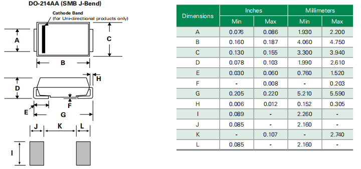
Package
SMBJ60CA Manufacturer
Littelfuse, Inc. is an electronic manufacturing company situated in Chicago, Illinois. The company's major focus is circuit protection, although it also develops electronic switches and car sensors. Littelfuse first opened its doors in 1927. In addition to its world headquarters in Chicago, Illinois, Littelfuse has more than 40 sales, distribution, production, and engineering offices throughout the Americas, Europe, and Asia.
Datasheet PDF
- Datasheets :
- Environmental Information :
How does a transient voltage suppressor diode work?
Transient Voltage Suppressor Diode is a clamping device, so whenever the induced voltage exceeds the avalanche breakdown voltage, it absorbs the excess energy of the overvoltage event, and then it automatically resets after overvoltage condition.
Where should a TVS diode be placed?
Place TVs diode near the edge of the PCB. To enable the excessive surge current to be channeled to the chassis ground before damaging the transceiver, the placement of the TVS diode is also important. It is a good practice to place TVS diodes as close to the edge of the board as possible.
Does TVS diode have polarity?
The -C and -CA diodes are bidirectional, there is no polarity marker. On unidirectional diodes, the color band usually denotes the cathode.
How do you specify a TVS diode?
1. Select a diode with a standoff voltage that is higher than the normal operating voltage. Ensure that the TVS diode maximum clamping voltage is less than the abs max rating of all the devices on the line to be protected. It is important to consider operation during both the transient event (a higher conduction current will result in a higher clamping voltage, for example) and during normal operation when a transient event is not present.
2. Verify that the specified peak current exceeds the expected peak current. Ensure that the diode is specified to handle the required power during a transient event. Diodes that are too small, or are not designed for a given current, may fail and cause the circuit to be destroyed during a surge or EFT event.
3. Calculate the maximum clamping voltage (VCL) of the selected diode. TVS diode datasheets typically list the VCL for a given IPP in the part selection table. For other peak pulse currents, however, this VCL may not be valid. To accommodate other IPP values, the TVS diode manufacturer gives a formula in the datasheet to calculate the VCL. Use this formula to calculate the VCL for a given IPP.
4. Confirm that the calculated VCL is less than the specified abs max rating for the pin.
 LIS3DH Accelerometer: Datasheet, Pinout, Functionality, and Block Diagram
08 July 20219677
 MCP41010 Potentiometer: Circuit, Pinout, and Datasheet
15 October 20218788
 SHT21 Temperature Sensor: Pinout, Datasheet and Application
15 July 20214005
 LT3750 Capacitor Charger Controller: Datasheet, Circuit, Equivalent
13 October 20212708
![TL431ACLP Shunt Voltage Reference IC Adjustable 2.495V 100mA[FAQ]: Datasheet, Features, and Pinout](https://res.utmel.com/Images/Article/4ac425df-f9a3-4fa9-84f6-68008d9b38f1.jpg) TL431ACLP Shunt Voltage Reference IC Adjustable 2.495V 100mA[FAQ]: Datasheet, Features, and Pinout
TL431ACLP Shunt Voltage Reference IC Adjustable 2.495V 100mA[FAQ]: Datasheet, Features, and Pinout16 March 20221055
 STM32F030C6T6 vs STM32F072C8T6 STMicroelectronics Microcontrollers
11 June 2025815
![MCP6022 Op Amps: Circuit, Pinout, and Datasheet [Video]](https://res.utmel.com/Images/Article/6f83275d-7623-4529-93f1-012e979a7d1d.png) MCP6022 Op Amps: Circuit, Pinout, and Datasheet [Video]
MCP6022 Op Amps: Circuit, Pinout, and Datasheet [Video]29 October 20217935
 HMC5883L Digital Compass IC: Pinout, Datasheet and Alternatives
06 September 20214998
 Classification and Application of UV Sensor
20 October 20215728
 What is GDDR?
25 November 202114544
 Constructing Hybrid Photovoltaics from Amorphous Silicon and Hybrid Semiconductor Nanocrystals
24 October 20221790
 Shift Registers Made Simple for New Learners
15 July 20254005
 Introduction to Centrifugal Switch
27 January 202114630
 QUIC: The Next Generation Communication Protocol
22 February 20222237
 What causes the Noise of Electronic Equipment when it is Running?
01 August 20223375
 Buffer Amplifier | Operating Principle, Advantages, and Applications
21 July 202510713
Littelfuse Inc.
In Stock: 27849
Minimum: 1 Multiples: 1
Qty
Unit Price
Ext Price
1
$0.069009
$0.07
10
$0.065103
$0.65
100
$0.061418
$6.14
500
$0.057942
$28.97
1000
$0.054662
$54.66
Not the price you want? Send RFQ Now and we'll contact you ASAP.
Inquire for More Quantity
![SM12-02HTG]() SM12-02HTG
SM12-02HTGLittelfuse Inc.
![SPHV24-01ETG-C]() SPHV24-01ETG-C
SPHV24-01ETG-CLittelfuse Inc.
![SM15-02HTG]() SM15-02HTG
SM15-02HTGLittelfuse Inc.
![SP1004U-ULC-04UTG]() SP1004U-ULC-04UTG
SP1004U-ULC-04UTGLittelfuse Inc.
![SP4024-01FTG-C]() SP4024-01FTG-C
SP4024-01FTG-CLittelfuse Inc.
![SD15-01FTG]() SD15-01FTG
SD15-01FTGLittelfuse Inc.
![SD24-01FTG]() SD24-01FTG
SD24-01FTGLittelfuse Inc.
![SP3022-01WTG]() SP3022-01WTG
SP3022-01WTGLittelfuse Inc.
![SD36-01FTG]() SD36-01FTG
SD36-01FTGLittelfuse Inc.
![SMAJ350CA]() SMAJ350CA
SMAJ350CALittelfuse Inc.


