
SN74HC74N Flip-Flop: Pinout, Applications and Datasheet


2V~6V 60MHz D-Type Flip Flop DUAL 74HC74 14 Pins 74HC Series 14-DIP (0.300, 7.62mm)
The Texas Instruments SN74HC74N is a dual D-type positive-edge-triggered flip-flop with clear and preset. This article will introduce its pinout, applications and datasheet.
SN74HC74N Description
The Texas Instruments SN74HC74N is a dual D-type positive-edge-triggered flip-flop with clear and preset. It is a logic device that can store one bit of data and change its output state according to the input signals. It has two independent flip-flops, each with a data (D) input, a clock (CLK) input, a clear (CLR) input, a preset (PRE) input, and a complementary output (Q and Q’). The flip-flop can be set or reset by the PRE and CLR inputs, regardless of the clock signal. When PRE and CLR are both high, the flip-flop changes state on the positive-going edge of the clock signal. The SN74HC74N operates from a 2V to 6V supply voltage and can handle clock frequencies up to 60 MHz. It is available in a 14-pin DIP package and is compatible with standard CMOS logic families.
SN74HC74N Features
It is a dual D-type positive-edge-triggered flip-flop with clear and preset. A flip-flop is a logic device that can store one bit of data and change its output state according to the input signals.
It has two independent flip-flops, each with a data (D) input, a clock (CLK) input, a clear (CLR) input, a preset (PRE) input, and a complementary output (Q and Q’). The flip-flop can be set or reset by the PRE and CLR inputs, regardless of the clock signal. When PRE and CLR are both high, the flip-flop changes state on the positive-going edge of the clock signal.
It operates from a 2V to 6V supply voltage and can handle clock frequencies up to 60 MHz. It is available in a 14-pin DIP package and is compatible with standard CMOS logic families.
It can be used for various applications such as converting a momentary switch to a toggle switch, dividing a clock signal by 2 or 4, or storing data in registers or counters.
Specifications
- TypeParameter
- Lifecycle Status
Lifecycle Status refers to the current stage of an electronic component in its product life cycle, indicating whether it is active, obsolete, or transitioning between these states. An active status means the component is in production and available for purchase. An obsolete status indicates that the component is no longer being manufactured or supported, and manufacturers typically provide a limited time frame for support. Understanding the lifecycle status is crucial for design engineers to ensure continuity and reliability in their projects.
ACTIVE (Last Updated: 6 days ago) - Factory Lead Time12 Weeks
- Contact Plating
Contact plating (finish) provides corrosion protection for base metals and optimizes the mechanical and electrical properties of the contact interfaces.
Gold - Mount
In electronic components, the term "Mount" typically refers to the method or process of physically attaching or fixing a component onto a circuit board or other electronic device. This can involve soldering, adhesive bonding, or other techniques to secure the component in place. The mounting process is crucial for ensuring proper electrical connections and mechanical stability within the electronic system. Different components may have specific mounting requirements based on their size, shape, and function, and manufacturers provide guidelines for proper mounting procedures to ensure optimal performance and reliability of the electronic device.
Through Hole - Mounting Type
The "Mounting Type" in electronic components refers to the method used to attach or connect a component to a circuit board or other substrate, such as through-hole, surface-mount, or panel mount.
Through Hole - Package / Case
refers to the protective housing that encases an electronic component, providing mechanical support, electrical connections, and thermal management.
14-DIP (0.300, 7.62mm) - Number of Pins14
- Weight927.99329mg
- Manufacturer Package Identifier
The Manufacturer Package Identifier is a unique code or label assigned by the manufacturer to identify a specific package or housing style of an electronic component. This identifier helps in distinguishing between different package types of the same component, such as integrated circuits, transistors, or diodes. It typically includes information about the package dimensions, lead configuration, and other physical characteristics of the component. The Manufacturer Package Identifier is crucial for ensuring compatibility and proper assembly of electronic components in various devices and circuits.
J (R-GDIP-T**) - Clock-Edge Trigger TypePositive Edge
- Operating Temperature
The operating temperature is the range of ambient temperature within which a power supply, or any other electrical equipment, operate in. This ranges from a minimum operating temperature, to a peak or maximum operating temperature, outside which, the power supply may fail.
-40°C~85°C TA - Packaging
Semiconductor package is a carrier / shell used to contain and cover one or more semiconductor components or integrated circuits. The material of the shell can be metal, plastic, glass or ceramic.
Tube - Series
In electronic components, the "Series" refers to a group of products that share similar characteristics, designs, or functionalities, often produced by the same manufacturer. These components within a series typically have common specifications but may vary in terms of voltage, power, or packaging to meet different application needs. The series name helps identify and differentiate between various product lines within a manufacturer's catalog.
74HC - JESD-609 Code
The "JESD-609 Code" in electronic components refers to a standardized marking code that indicates the lead-free solder composition and finish of electronic components for compliance with environmental regulations.
e4 - Part Status
Parts can have many statuses as they progress through the configuration, analysis, review, and approval stages.
Active - Moisture Sensitivity Level (MSL)
Moisture Sensitivity Level (MSL) is a standardized rating that indicates the susceptibility of electronic components, particularly semiconductors, to moisture-induced damage during storage and the soldering process, defining the allowable exposure time to ambient conditions before they require special handling or baking to prevent failures
1 (Unlimited) - Number of Terminations14
- ECCN Code
An ECCN (Export Control Classification Number) is an alphanumeric code used by the U.S. Bureau of Industry and Security to identify and categorize electronic components and other dual-use items that may require an export license based on their technical characteristics and potential for military use.
EAR99 - TypeD-Type
- Voltage - Supply
Voltage - Supply refers to the range of voltage levels that an electronic component or circuit is designed to operate with. It indicates the minimum and maximum supply voltage that can be applied for the device to function properly. Providing supply voltages outside this range can lead to malfunction, damage, or reduced performance. This parameter is critical for ensuring compatibility between different components in a circuit.
2V~6V - Terminal Position
In electronic components, the term "Terminal Position" refers to the physical location of the connection points on the component where external electrical connections can be made. These connection points, known as terminals, are typically used to attach wires, leads, or other components to the main body of the electronic component. The terminal position is important for ensuring proper connectivity and functionality of the component within a circuit. It is often specified in technical datasheets or component specifications to help designers and engineers understand how to properly integrate the component into their circuit designs.
DUAL - Supply Voltage
Supply voltage refers to the electrical potential difference provided to an electronic component or circuit. It is crucial for the proper operation of devices, as it powers their functions and determines performance characteristics. The supply voltage must be within specified limits to ensure reliability and prevent damage to components. Different electronic devices have specific supply voltage requirements, which can vary widely depending on their design and intended application.
5V - Base Part Number
The "Base Part Number" (BPN) in electronic components serves a similar purpose to the "Base Product Number." It refers to the primary identifier for a component that captures the essential characteristics shared by a group of similar components. The BPN provides a fundamental way to reference a family or series of components without specifying all the variations and specific details.
74HC74 - Function
The parameter "Function" in electronic components refers to the specific role or purpose that the component serves within an electronic circuit. It defines how the component interacts with other elements, influences the flow of electrical signals, and contributes to the overall behavior of the system. Functions can include amplification, signal processing, switching, filtering, and energy storage, among others. Understanding the function of each component is essential for designing effective and efficient electronic systems.
Set(Preset) and Reset - Output Type
The "Output Type" parameter in electronic components refers to the type of signal or data that is produced by the component as an output. This parameter specifies the nature of the output signal, such as analog or digital, and can also include details about the voltage levels, current levels, frequency, and other characteristics of the output signal. Understanding the output type of a component is crucial for ensuring compatibility with other components in a circuit or system, as well as for determining how the output signal can be utilized or processed further. In summary, the output type parameter provides essential information about the nature of the signal that is generated by the electronic component as its output.
Differential - Operating Supply Voltage
The voltage level by which an electrical system is designated and to which certain operating characteristics of the system are related.
5V - Polarity
In electronic components, polarity refers to the orientation or direction in which the component must be connected in a circuit to function properly. Components such as diodes, capacitors, and LEDs have polarity markings to indicate which terminal should be connected to the positive or negative side of the circuit. Connecting a component with incorrect polarity can lead to malfunction or damage. It is important to pay attention to polarity markings and follow the manufacturer's instructions to ensure proper operation of electronic components.
Non-Inverting - Supply Voltage-Max (Vsup)
The parameter "Supply Voltage-Max (Vsup)" in electronic components refers to the maximum voltage that can be safely applied to the component without causing damage. It is an important specification to consider when designing or using electronic circuits to ensure the component operates within its safe operating limits. Exceeding the maximum supply voltage can lead to overheating, component failure, or even permanent damage. It is crucial to adhere to the specified maximum supply voltage to ensure the reliable and safe operation of the electronic component.
6V - Supply Voltage-Min (Vsup)
The parameter "Supply Voltage-Min (Vsup)" in electronic components refers to the minimum voltage level required for the component to operate within its specified performance range. This parameter indicates the lowest voltage that can be safely applied to the component without risking damage or malfunction. It is crucial to ensure that the supply voltage provided to the component meets or exceeds this minimum value to ensure proper functionality and reliability. Failure to adhere to the specified minimum supply voltage may result in erratic behavior, reduced performance, or even permanent damage to the component.
2V - Number of Channels2
- Load Capacitance
the amount of capacitance measured or computed across the crystal terminals on the PCB. Frequency Tolerance. Frequency tolerance refers to the allowable deviation from nominal, in parts per million (PPM), at a specific temperature, usually +25°C.
50pF - Output Current
The rated output current is the maximum load current that a power supply can provide at a specified ambient temperature. A power supply can never provide more current that it's rated output current unless there is a fault, such as short circuit at the load.
5.2mA - Clock Frequency
Clock frequency, also known as clock speed, refers to the rate at which a processor or electronic component can execute instructions. It is measured in hertz (Hz) and represents the number of cycles per second that the component can perform. A higher clock frequency typically indicates a faster processing speed and better performance. However, it is important to note that other factors such as architecture, efficiency, and workload also play a significant role in determining the overall performance of a component. In summary, clock frequency is a crucial parameter that influences the speed and efficiency of electronic components in processing data and executing tasks.
60MHz - Propagation Delay
the flight time of packets over the transmission link and is limited by the speed of light.
175 ns - Quiescent Current
The quiescent current is defined as the current level in the amplifier when it is producing an output of zero.
4μA - Turn On Delay Time
Turn-on delay, td(on), is the time taken to charge the input capacitance of the device before drain current conduction can start.
15 ns - Family
In electronic components, the parameter "Family" typically refers to a categorization or classification system used to group similar components together based on their characteristics, functions, or applications. This classification helps users easily identify and select components that meet their specific requirements. The "Family" parameter can include various subcategories such as resistors, capacitors, diodes, transistors, integrated circuits, and more. Understanding the "Family" of an electronic component can provide valuable information about its compatibility, performance specifications, and potential uses within a circuit or system. It is important to consider the "Family" parameter when designing or troubleshooting electronic circuits to ensure proper functionality and compatibility with other components.
HC/UH - Logic Function
In electronic components, the term "Logic Function" refers to the specific operation or behavior of a component based on its input signals. It describes how the component processes the input signals to produce the desired output. Logic functions are fundamental to digital circuits and are used to perform logical operations such as AND, OR, NOT, and XOR.Each electronic component, such as logic gates or flip-flops, is designed to perform a specific logic function based on its internal circuitry. By understanding the logic function of a component, engineers can design and analyze complex digital systems to ensure proper functionality and performance. Different logic functions can be combined to create more complex operations, allowing for the creation of sophisticated digital devices and systems.
AND, D-Type, Flip-Flop - Number of Bits per Element1
- Max Propagation Delay @ V, Max CL
The parameter "Max Propagation Delay @ V, Max CL" in electronic components refers to the maximum amount of time it takes for a signal to propagate through the component from input to output when operating at a specific voltage (V) and driving a maximum specified load capacitance (CL). This parameter is crucial in determining the speed and performance of the component in a circuit. A shorter propagation delay indicates faster signal processing and better overall performance. Designers use this parameter to ensure that signals can be transmitted and received within the required timing constraints in their electronic systems.
30ns @ 6V, 50pF - Trigger Type
Trigger Type in electronic components refers to the mechanism or method by which a device, such as a flip-flop or timer, responds to an input signal. It defines how the device transitions between states based on specific conditions, such as rising or falling edges of a signal, levels, or pulses. Different trigger types such as edge-triggered, level-triggered, or pulse-triggered influence the timing and behavior of the circuit, thereby determining how input signals affect the output in various applications.
Positive Edge - Input Capacitance
The capacitance between the input terminals of an op amp with either input grounded. It is expressed in units of farads.
3pF - Number of Input Lines4
- Height5.08mm
- Length19.3mm
- Width6.35mm
- Thickness
Thickness in electronic components refers to the measurement of how thick a particular material or layer is within the component structure. It can pertain to various aspects, such as the thickness of a substrate, a dielectric layer, or conductive traces. This parameter is crucial as it impacts the electrical, mechanical, and thermal properties of the component, influencing its performance and reliability in electronic circuits.
3.9mm - REACH SVHC
The parameter "REACH SVHC" in electronic components refers to the compliance with the Registration, Evaluation, Authorization, and Restriction of Chemicals (REACH) regulation regarding Substances of Very High Concern (SVHC). SVHCs are substances that may have serious effects on human health or the environment, and their use is regulated under REACH to ensure their safe handling and minimize their impact.Manufacturers of electronic components need to declare if their products contain any SVHCs above a certain threshold concentration and provide information on the safe use of these substances. This information allows customers to make informed decisions about the potential risks associated with using the components and take appropriate measures to mitigate any hazards.Ensuring compliance with REACH SVHC requirements is essential for electronics manufacturers to meet regulatory standards, protect human health and the environment, and maintain transparency in their supply chain. It also demonstrates a commitment to sustainability and responsible manufacturing practices in the electronics industry.
No SVHC - Radiation Hardening
Radiation hardening is the process of making electronic components and circuits resistant to damage or malfunction caused by high levels of ionizing radiation, especially for environments in outer space (especially beyond the low Earth orbit), around nuclear reactors and particle accelerators, or during nuclear accidents or nuclear warfare.
No - RoHS Status
RoHS means “Restriction of Certain Hazardous Substances” in the “Hazardous Substances Directive” in electrical and electronic equipment.
ROHS3 Compliant - Lead Free
Lead Free is a term used to describe electronic components that do not contain lead as part of their composition. Lead is a toxic material that can have harmful effects on human health and the environment, so the electronics industry has been moving towards lead-free components to reduce these risks. Lead-free components are typically made using alternative materials such as silver, copper, and tin. Manufacturers must comply with regulations such as the Restriction of Hazardous Substances (RoHS) directive to ensure that their products are lead-free and environmentally friendly.
Lead Free
SN74HC74N Pinout

SN74HC74N CAD Model
Symbol

Footprint

3D Model

SN74HC74N Alternatives
Part Number | Description | Manufacturer |
MN74HC74 | D Flip-Flop, HC/UH Series, 2-Func, Positive Edge Triggered, 1-Bit, Complementary Output, CMOS, PDIP14, PLASTIC, DIP-14 | Panasonic Electronic Components |
TC74HC74AP | IC HC/UH SERIES, DUAL POSITIVE EDGE TRIGGERED D FLIP-FLOP, COMPLEMENTARY OUTPUT, PDIP14, 0.300 INCH, 2.54 MM PITCH, LEAD FREE, PLASTIC, DIP-14, FF/Latch | Toshiba America Electronic Components |
SN74HC74N Applications
Converting a momentary switch to a toggle switch: A momentary switch is a switch that only stays on or off while being pressed. A toggle switch is a switch that maintains its state after being toggled. The SN74HC74N can be used to convert a momentary switch to a toggle switch by connecting the switch to the data input and the clock input of the flip-flop. The output of the flip-flop will change state every time the switch is pressed and released, and will stay in that state until the next press. This can be useful for applications that require a switch to control a device or a circuit that needs to be turned on or off alternately. For example, a momentary switch can be converted to a toggle switch to control a LED light or a relay. You can find a schematic diagram of this application in the datasheet1 or in this web page.
Dividing a clock signal by 2 or 4: A clock signal is a periodic signal that is used to synchronize the operation of digital circuits. The SN74HC74N can be used to divide a clock signal by 2 or 4 by connecting the clock signal to the clock input of one or two flip-flops. The output of the first flip-flop will have half the frequency of the input clock signal, and the output of the second flip-flop will have one-fourth the frequency of the input clock signal. This can be useful for applications that require a lower frequency clock signal for timing or counting purposes. For example, a clock signal can be divided by 2 or 4 to generate a pulse width modulated (PWM) signal or a binary counter. You can find a schematic diagram of this application in the datasheet1 or in this web page.
Storing data in registers or counters: A register is a device that can store one or more bits of data and can be read or written by other devices. A counter is a device that can count the number of pulses or events that occur in a given time interval. The SN74HC74N can be used to store data in registers or counters by connecting the data input and the clock input of the flip-flop to the data source and the clock source, respectively. The output of the flip-flop will store the data that is present at the data input when the clock signal changes from low to high. This can be useful for applications that require data storage or manipulation. For example, a register can be used to store the state of a switch or a sensor, and a counter can be used to measure the frequency or the duration of a signal. You can find a schematic diagram of this application in the datasheet or in this web page.
SN74HC74N Manufacturer
Texas Instruments is a company that designs and manufactures semiconductors and various integrated circuits, which it sells to electronics designers and manufacturers globally It is one of the top 10 semiconductor companies worldwide based on sales volume The company’s focus is on developing analog chips and embedded processors, which account for more than 80% of its revenue TI also produces TI digital light processing technology and education technology products including calculators, microcontrollers, and multi-core processors The company holds 45,000 patents worldwide as of 2016.
Parts with Similar Specs
- ImagePart NumberManufacturerPackage / CaseNumber of PinsLogic FunctionNumber of Bits per ElementPropagation DelayClock Edge Trigger TypeSupply VoltageQuiescent CurrentView Compare
![SN74HC74N]()
SN74HC74N
14-DIP (0.300, 7.62mm)
14
AND, D-Type, Flip-Flop
1
175 ns
Positive Edge
5 V
4 μA
![SN74HCT74N]()
14-DIP (0.300, 7.62mm)
14
AND, D-Type, Flip-Flop
1
28 ns
Positive Edge
5 V
4 μA
![MC74HC74ANG]()
14-DIP (0.300, 7.62mm)
14
AND, D-Type, Flip-Flop
1
100 ns
Positive Edge
3 V
-
![SN74HC109N]()
14-DIP (0.300, 7.62mm)
14
AND, D-Type, Flip-Flop
1
35 ns
Positive Edge
5 V
4 μA
![CD74HCT74E]()
16-DIP (0.300, 7.62mm)
16
AND, Flip-Flop, JK-Type
1
175 ns
Positive Edge
5 V
4 μA


Datasheet PDF
- PCN Design/Specification :
- Datasheets :
SN74HC74N-Texas-Instruments-datasheet-48050967.pdf
SN74HC74N-Texas-Instruments-datasheet-11727171.pdf
SN74HC74N-Texas-Instruments-datasheet-14146539.pdf
SN74HC74N-Texas-Instruments-datasheet-10257117.pdf
SN74HC74N-Texas-Instruments-datasheet-8097698.pdf
SN74HC74N-Texas-Instruments-datasheet-11144.pdf
SN74HC74N-Texas-Instruments-datasheet-62088867.pdf
SN74HC74N-Texas-Instruments-datasheet-46790.pdf
What is the difference between the SN74HC74 and the SN74HCT74?
The SN74HC74 and the SN74HCT74 are both dual D-type positive-edge-triggered flip-flops with clear and preset, but they have different input and output voltage levels. The SN74HC74 is compatible with standard CMOS logic families, while the SN74HCT74 is compatible with TTL logic families. The SN74HC74 has a supply voltage range of 2V to 6V, while the SN74HCT74 has a supply voltage range of 4.5V to 5.5V. The SN74HC74 has a typical input threshold voltage of 1.35V, while the SN74HCT74 has a typical input threshold voltage of 1.5V. The SN74HC74 has a typical output voltage of VCC, while the SN74HCT74 has a typical output voltage of 3.7V.
How can I use the SN74HC74 to generate a PWM signal?
A PWM (pulse width modulation) signal is a signal that has a variable duty cycle, which is the ratio of the on time to the total period of the signal. A PWM signal can be used to control the speed of a motor, the brightness of a LED, or the power of a device. The SN74HC74 can be used to generate a PWM signal by connecting the clock input (CLK) to a fixed frequency clock source, the data input (D) to a variable voltage source, and the output (Q) to the PWM output. The variable voltage source can be a potentiometer, a DAC, or a sensor. The duty cycle of the PWM signal will depend on the voltage level of the data input. When the data input is high, the output will change state on every positive edge of the clock signal, resulting in a 50% duty cycle. When the data input is low, the output will remain in the same state, resulting in a 0% or 100% duty cycle. When the data input is between high and low, the output will change state on some of the positive edges of the clock signal, resulting in a variable duty cycle. You can find a schematic diagram of this application in this web page.
How can I cascade multiple SN74HC74 devices to create a larger register or counter?
A register is a device that can store one or more bits of data and can be read or written by other devices. A counter is a device that can count the number of pulses or events that occur in a given time interval. The SN74HC74 can be used to create a register or a counter by connecting the data input (D) and the clock input (CLK) of the flip-flop to the data source and the clock source, respectively. The output (Q) of the flip-flop will store the data that is present at the data input when the clock signal changes from low to high. To cascade multiple SN74HC74 devices to create a larger register or counter, the output (Q) of one flip-flop can be connected to the data input (D) of the next flip-flop, and the clock input (CLK) of all the flip-flops can be connected to the same clock source. The number of bits in the register or counter will depend on the number of flip-flops used. For example, two SN74HC74 devices can be cascaded to create a 4-bit register or counter, four SN74HC74 devices can be cascaded to create an 8-bit register or counter, and so on.
 AT28C64 64K Parallel EEPROM: Pinout, Equivalent and Datasheet
22 April 20222017
 A Comprehensive Guide to LTC6945IUFD#TRPBF PLL Frequency Synthesizer
06 March 2024260
 2N3906 VS 2N2222 VS 2N3904: What are the Differences?
13 April 202212918
 OP27CJ8 Linear Amplifier: Product Overview and Applications
06 March 202489
 LME49600 Audio Buffer: Datasheet, Pinout and Schematic
31 August 20212336
 74HC595 Shift Register IC : Pinout, Advantage and Datasheet
13 September 20217970
 TL1431 Adjustable Voltage Reference: Pinout, Specification and Datasheet
19 November 20211393
 Essential Tips for Resolving STM32F407ZET6 Connectivity Issues
24 July 2025291
 Comparing Popular Jumper Wires for Electronics Projects
10 July 20251074
 What are Laser Diodes?
20 October 202514275
 Degson Authorized Distributor | UTMEL Electronics
21 November 20232337
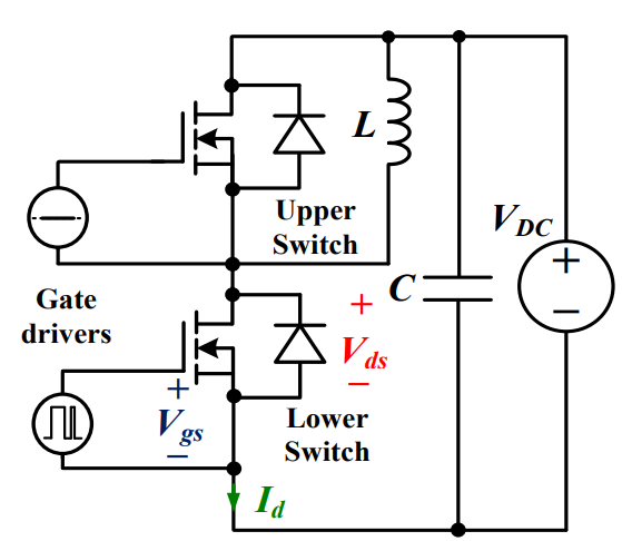 Discovering New and Advanced Methodology for Determining the Dynamic Characterization of Wide Bandgap Devices
15 March 20242366
 Understanding Adapter Cards in Modern Computers
05 July 2025907
 Varistor: Definition, Function, Working and Testing
03 April 202580857
 Characteristics, Types, and Functions of Electrolytic Capacitors
17 October 20259466
 Good News: UTMEL Electronic is now the Authorized Distributor for Isocom Components 2004 Ltd.
10 November 20236562
Texas Instruments
In Stock: 12
United States
China
Canada
Japan
Russia
Germany
United Kingdom
Singapore
Italy
Hong Kong(China)
Taiwan(China)
France
Korea
Mexico
Netherlands
Malaysia
Austria
Spain
Switzerland
Poland
Thailand
Vietnam
India
United Arab Emirates
Afghanistan
Åland Islands
Albania
Algeria
American Samoa
Andorra
Angola
Anguilla
Antigua & Barbuda
Argentina
Armenia
Aruba
Australia
Azerbaijan
Bahamas
Bahrain
Bangladesh
Barbados
Belarus
Belgium
Belize
Benin
Bermuda
Bhutan
Bolivia
Bonaire, Sint Eustatius and Saba
Bosnia & Herzegovina
Botswana
Brazil
British Indian Ocean Territory
British Virgin Islands
Brunei
Bulgaria
Burkina Faso
Burundi
Cabo Verde
Cambodia
Cameroon
Cayman Islands
Central African Republic
Chad
Chile
Christmas Island
Cocos (Keeling) Islands
Colombia
Comoros
Congo
Congo (DRC)
Cook Islands
Costa Rica
Côte d’Ivoire
Croatia
Cuba
Curaçao
Cyprus
Czechia
Denmark
Djibouti
Dominica
Dominican Republic
Ecuador
Egypt
El Salvador
Equatorial Guinea
Eritrea
Estonia
Eswatini
Ethiopia
Falkland Islands
Faroe Islands
Fiji
Finland
French Guiana
French Polynesia
Gabon
Gambia
Georgia
Ghana
Gibraltar
Greece
Greenland
Grenada
Guadeloupe
Guam
Guatemala
Guernsey
Guinea
Guinea-Bissau
Guyana
Haiti
Honduras
Hungary
Iceland
Indonesia
Iran
Iraq
Ireland
Isle of Man
Israel
Jamaica
Jersey
Jordan
Kazakhstan
Kenya
Kiribati
Kosovo
Kuwait
Kyrgyzstan
Laos
Latvia
Lebanon
Lesotho
Liberia
Libya
Liechtenstein
Lithuania
Luxembourg
Macao(China)
Madagascar
Malawi
Maldives
Mali
Malta
Marshall Islands
Martinique
Mauritania
Mauritius
Mayotte
Micronesia
Moldova
Monaco
Mongolia
Montenegro
Montserrat
Morocco
Mozambique
Myanmar
Namibia
Nauru
Nepal
New Caledonia
New Zealand
Nicaragua
Niger
Nigeria
Niue
Norfolk Island
North Korea
North Macedonia
Northern Mariana Islands
Norway
Oman
Pakistan
Palau
Palestinian Authority
Panama
Papua New Guinea
Paraguay
Peru
Philippines
Pitcairn Islands
Portugal
Puerto Rico
Qatar
Réunion
Romania
Rwanda
Samoa
San Marino
São Tomé & Príncipe
Saudi Arabia
Senegal
Serbia
Seychelles
Sierra Leone
Sint Maarten
Slovakia
Slovenia
Solomon Islands
Somalia
South Africa
South Sudan
Sri Lanka
St Helena, Ascension, Tristan da Cunha
St. Barthélemy
St. Kitts & Nevis
St. Lucia
St. Martin
St. Pierre & Miquelon
St. Vincent & Grenadines
Sudan
Suriname
Svalbard & Jan Mayen
Sweden
Syria
Tajikistan
Tanzania
Timor-Leste
Togo
Tokelau
Tonga
Trinidad & Tobago
Tunisia
Turkey
Turkmenistan
Turks & Caicos Islands
Tuvalu
U.S. Outlying Islands
U.S. Virgin Islands
Uganda
Ukraine
Uruguay
Uzbekistan
Vanuatu
Vatican City
Venezuela
Wallis & Futuna
Yemen
Zambia
Zimbabwe
![SN74LVC1G175DCKR]() SN74LVC1G175DCKR
SN74LVC1G175DCKRTexas Instruments
![SN74AHC74RGYR]() SN74AHC74RGYR
SN74AHC74RGYRTexas Instruments
![SN74LVC2G74DCTR]() SN74LVC2G74DCTR
SN74LVC2G74DCTRTexas Instruments
![SN74LVC2G74DCUR]() SN74LVC2G74DCUR
SN74LVC2G74DCURTexas Instruments
![SN74HC74PWR]() SN74HC74PWR
SN74HC74PWRTexas Instruments
![SN74HC74DR]() SN74HC74DR
SN74HC74DRTexas Instruments
![SN74HC273DWR]() SN74HC273DWR
SN74HC273DWRTexas Instruments
![SN74HC273DW]() SN74HC273DW
SN74HC273DWTexas Instruments
![SN74HC175DR]() SN74HC175DR
SN74HC175DRTexas Instruments
![CD4013BM]() CD4013BM
CD4013BMTexas Instruments


