
 Product
 Brand
Brand Articles
 Tools
Tools
Step-by-Step NXP MKL03Z32CAF4 Programming Guide


32KB Flash Microcontroller
Learn how to set up and program the MKL03Z32CAF4 microcontroller with this beginner-friendly guide. Includes hardware setup, IDE configuration, and coding tips.
Product Introduction
Getting started with the MKL03Z32CAF4 doesn’t have to feel overwhelming. This guide breaks everything into simple steps, from setting up the hardware to uploading your first program. Whether you’re new to microcontrollers or just starting out, you’ll find it easy to follow and build confidence as you go.
Understanding the MKL03Z32CAF4
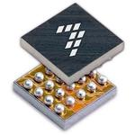
Overview of the MKL03Z32CAF4 Microcontroller
The MKL03Z32CAF4 is a compact and efficient microcontroller designed for low-power applications. It belongs to the Kinetis L series, which is known for its energy efficiency and performance. This microcontroller is built on the ARM Cortex-M0+ core, making it a great choice for projects that require a balance between power consumption and functionality.
You’ll find the MKL03Z32CAF4 ideal for small-scale projects like wearable devices, IoT gadgets, or simple automation systems. Its small size and low power requirements make it perfect for battery-operated devices. Plus, it’s beginner-friendly, so you don’t need to be an expert to get started.
Did you know? The MKL03Z32CAF4 supports a wide range of peripherals, including GPIOs, timers, and communication interfaces like I2C and SPI. This versatility allows you to experiment with different types of projects.
Key Features and Benefits for Beginners
The MKL03Z32CAF4 comes packed with features that make it a fantastic choice for beginners. Here are some highlights:
Low Power Consumption: It’s designed to operate efficiently, which is great for devices that need to run on batteries for a long time.
Small Footprint: Its compact size makes it easy to integrate into tight spaces.
User-Friendly Development Tools: You can use tools like MCUXpresso IDE, which simplifies programming and debugging.
Rich Peripheral Set: It includes essential interfaces like UART, I2C, and SPI, giving you the flexibility to connect various sensors and modules.
Affordable: The MKL03Z32CAF4 is budget-friendly, making it accessible for hobbyists and students.
These features make it easier for you to dive into the world of microcontrollers. You can start with simple projects like blinking an LED and gradually move on to more complex applications.
Tools and Components Required
Essential Hardware for MKL03Z32CAF4 Setup
To get started with the MKL03Z32CAF4, you’ll need some basic hardware components. Here’s a quick list to help you gather everything:
Development Board: A compatible development board for the MKL03Z32CAF4, such as the FRDM-KL03Z, simplifies connections and testing.
Power Supply: A reliable 3.3V power source ensures safe operation.
Debugging Tool: A J-Link or OpenSDA debugger lets you upload and debug your programs.
Additional Components: Depending on your project, you might need sensors, LEDs, or buttons.
For more advanced setups, consider these parts:
| Part Name | Description | Link |
|---|---|---|
| CAT24AA01WI-GT3 | 128 X 8 I2C/2-WIRE SERIAL EEPROM, PDSO8, 2 X 3 MM, 0.75 MM HEIGHT, ROHS COMPLIANT | Link |
| LM2674MX-ADJ | Switching Regulator or Controllers | Link |
| TPS3110K33DBVR | Power Management Circuits | Link |
These components expand your options for creating more complex projects.
Recommended Software Tools and IDEs
You’ll need software tools to program the MKL03Z32CAF4. The most beginner-friendly option is MCUXpresso IDE, which offers a clean interface and built-in support for Kinetis microcontrollers.
Other useful tools include:
Driver Installation Tools: Ensure your computer recognizes the debugging hardware.
SDKs: The NXP SDK provides libraries and examples tailored to the MKL03Z32CAF4.
These tools make programming easier and help you avoid common setup issues.
Additional Accessories for a Smooth Setup
A few extra accessories can make your setup more convenient:
Breadboard and Jumper Wires: These simplify connections during prototyping.
Multimeter: Use this to check voltage levels and troubleshoot circuits.
USB Cable: A high-quality USB cable ensures stable communication between your computer and the development board.
Tip: Keep your workspace organized. Label your components and cables to avoid confusion during setup.
Setting Up the Hardware
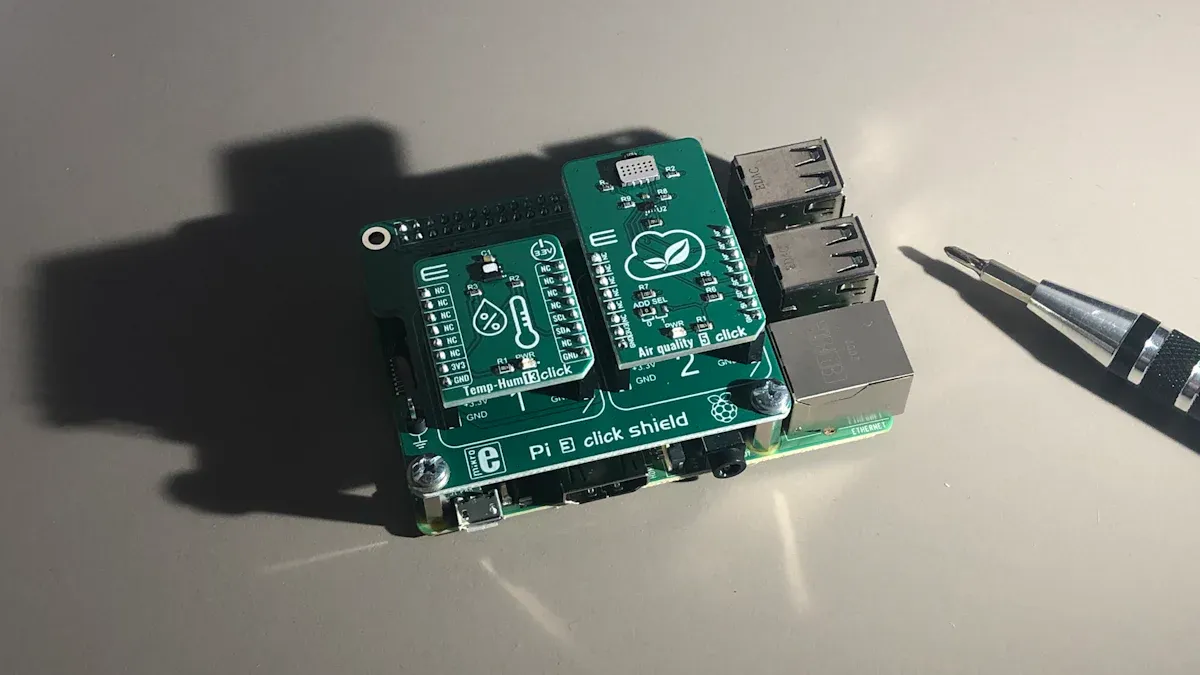
Connecting the MKL03Z32CAF4 to a Development Board
To get started, you’ll need to connect the MKL03Z32CAF4 to a compatible development board. This step is crucial because the development board acts as a bridge between your computer and the microcontroller, making programming and testing much easier.
Here’s how you can do it:
Identify the Pin Layout: Check the datasheet or user manual of your development board to understand the pin configuration. Look for labels like VCC, GND, and GPIO pins.
Align the Microcontroller: Place the MKL03Z32CAF4 on the development board, ensuring the pins align correctly with the board’s sockets.
Secure the Connection: Use a soldering iron or a socket adapter to secure the microcontroller to the board. If you’re a beginner, a socket adapter is a safer option.
Tip: Double-check the pin alignment before powering up. A wrong connection can damage the microcontroller or the board.
Powering the Microcontroller Safely
Powering your microcontroller correctly is essential to avoid damaging it. The MKL03Z32CAF4 operates at 3.3V, so you’ll need a reliable power source that matches this requirement.
Follow these steps to power it safely:
Use a Regulated Power Supply: If you’re using an external power source, make sure it provides a stable 3.3V output.
Connect the Power Pins: Attach the VCC pin of the microcontroller to the 3.3V output and the GND pin to the ground of your power source.
Check Voltage Levels: Use a multimeter to verify the voltage before powering up the microcontroller.
Note: Avoid using a power source that exceeds 3.3V. Even a slight overvoltage can permanently damage the microcontroller.
Configuring Debugging Interfaces
Debugging is an important part of programming microcontrollers. It helps you identify and fix issues in your code. To debug the MKL03Z32CAF4, you’ll need to set up a debugging interface.
Here’s what you need to do:
Choose a Debugger: Popular options include J-Link and OpenSDA. These tools allow you to upload code and debug your programs.
Connect the Debugger: Use the appropriate cable to connect the debugger to the development board. Most boards have a dedicated debugging port labeled SWD (Serial Wire Debug).
Install Debugging Software: Install the necessary drivers and software for your debugger. For example, if you’re using J-Link, download the J-Link software package from SEGGER’s website.
Test the Connection: Open your IDE and check if the debugger detects the microcontroller. If it doesn’t, recheck your connections and ensure the drivers are installed correctly.
Pro Tip: Keep your debugging setup organized. Label your cables and ports to avoid confusion during troubleshooting.
Installing and Configuring the Software
Choosing and Downloading the Right IDE (e.g., MCUXpresso)
Picking the right IDE is the first step to programming the MKL03Z32CAF4. You want something that’s easy to use and supports this microcontroller. MCUXpresso IDE is a great choice. It’s free, beginner-friendly, and packed with features that simplify coding and debugging.
Here’s how you can get started:
Visit the NXP Website: Head over to NXP’s MCUXpresso IDE page to download the software.
Choose Your Version: Select the version compatible with your operating system (Windows, macOS, or Linux).
Download and Install: Follow the installation instructions provided on the website. The process is straightforward, and the installer guides you step by step.
Tip: Make sure your computer meets the minimum system requirements for MCUXpresso IDE. This ensures smooth performance while coding and debugging.
Once installed, you’ll have access to a powerful tool that makes programming the MKL03Z32CAF4 much easier.
Installing Necessary Drivers and SDKs
Drivers and SDKs are essential for your computer to communicate with the microcontroller and development board. Without them, your IDE won’t recognize the hardware.
Here’s what you need to do:
Install Debugger Drivers: If you’re using a J-Link or OpenSDA debugger, download the drivers from the manufacturer’s website. For J-Link, visit SEGGER’s site and grab the latest driver package.
Download the NXP SDK: Go to the NXP SDK Builder and create a custom SDK for the MKL03Z32CAF4. Select your development board and peripherals, then download the SDK package.
Install the SDK in MCUXpresso: Open MCUXpresso IDE, navigate to the “Installed SDKs” tab, and import the downloaded SDK.
Note: Always restart your computer after installing drivers. This ensures they’re properly loaded and ready to use.
With the drivers and SDKs in place, your IDE will be fully equipped to handle MKL03Z32CAF4 projects.
Configuring the IDE for MKL03Z32CAF4 Projects
Now that the software is installed, it’s time to set up your IDE for MKL03Z32CAF4 programming. This step ensures the IDE knows how to interact with your microcontroller.
Follow these steps to configure MCUXpresso IDE:
Create a New Workspace: Open MCUXpresso and set up a workspace folder where all your projects will be saved.
Import the SDK: Navigate to the “Installed SDKs” tab and select the MKL03Z32CAF4 SDK you imported earlier.
Start a New Project: Click “New Project” and choose the MKL03Z32CAF4 as your target device. The IDE will automatically configure the project settings based on the SDK.
Set Up Debugging: Go to the “Debug Configurations” menu and select your debugger (e.g., J-Link or OpenSDA). Test the connection to ensure everything is working.
Pro Tip: Enable the “Auto-Generate Code” option in the project settings. This saves time by creating boilerplate code for your microcontroller’s peripherals.
Once configured, your IDE is ready for coding. You can now start writing programs and uploading them to the MKL03Z32CAF4.
Writing and Uploading Your First Program
Creating a New Project in the IDE
Starting your first project in the IDE is simple. Open MCUXpresso and click on "New Project." A wizard will guide you through the setup. Select the MKL03Z32CAF4 as your target device. Choose the SDK you installed earlier, and let the IDE auto-configure the project settings for you.
Tip: Name your project something meaningful, like "LED_Blink," so you can easily identify it later.
Once the project is created, you’ll see a folder structure with files like main.c. This is where you’ll write your code.
Writing a Basic LED Blinking Program
Let’s start with a classic beginner project: blinking an LED. Open the main.c file and replace the default code with the following:
#include "MKL03Z4.h"

void delay(void) {
    for (volatile int i = 0; i < 100000; i++);
}

int main(void) {
    SIM->SCGC5 |= SIM_SCGC5_PORTB_MASK;
    PORTB->PCR[6] = PORT_PCR_MUX(1);
    GPIOB->PDDR |= (1 << 6);

    while (1) {
        GPIOB->PTOR = (1 << 6);
        delay();
    }
}
This code toggles an LED connected to pin B6. The delay() function creates a pause between each toggle.
Note: Make sure your development board has an LED connected to pin B6.
Compiling and Uploading the Program to the MKL03Z32CAF4
Now it’s time to bring your code to life. Click on the "Build" button in the IDE to compile your program. If there are no errors, connect your debugger to the development board and hit "Debug." The IDE will upload the program to the MKL03Z32CAF4.
Once uploaded, the LED should start blinking. If it doesn’t, check your connections and ensure the debugger is properly configured.
Pro Tip: Keep an eye on the console output in the IDE. It provides helpful messages during the upload process.
Testing and Troubleshooting
Verifying the Program Output on the MKL03Z32CAF4
Once you’ve uploaded your program, it’s time to see if it works as expected. For the LED blinking program, check if the LED on your development board is turning on and off at regular intervals. If it’s not, don’t worry—troubleshooting is part of the process!
Here’s a quick checklist to verify your setup:
Power Supply: Ensure the microcontroller is receiving a stable 3.3V.
Connections: Double-check the wiring between the MKL03Z32CAF4 and the development board.
Code Logic: Review your code to confirm the correct GPIO pin is being toggled.
Tip: If you’re unsure about the pin configuration, refer to the development board’s user manual. It often includes diagrams to help you identify the correct pins.
Debugging Common Issues for Beginners
If your program isn’t working, don’t panic. Debugging is a skill you’ll develop over time. Here are some common issues and how to fix them:
Incorrect Pin Assignment: Verify that the pin number in your code matches the physical pin connected to the LED.
Driver Issues: Ensure the debugger drivers are installed and up to date.
SDK Problems: Check if the correct SDK for the MKL03Z32CAF4 is imported into your IDE.
Pro Tip: Use the debugging tools in your IDE to step through the code. This helps you pinpoint where things might be going wrong.
Tips to Avoid Errors During Programming
You can save yourself a lot of frustration by following these tips:
Start Small: Begin with simple programs like blinking an LED before moving on to complex projects.
Comment Your Code: Add comments to explain what each part of your code does. This makes it easier to debug later.
Test Frequently: Upload and test your code in small increments. This way, you’ll catch errors early.
Reminder: Always back up your projects. Losing your work due to a mistake or hardware issue can be discouraging.
By following these steps, you’ll build confidence in programming the MKL03Z32CAF4 and troubleshooting any issues that arise.
You’ve learned how to set up, program, and troubleshoot the MKL03Z32CAF4 microcontroller. Now, it’s time to take your skills further!
Try projects like temperature monitoring or IoT devices.
Explore resources like NXP’s forums and GitHub repositories.
Tip: Join online communities to share ideas and get support.
FAQ
What should I do if my program doesn’t upload to the MKL03Z32CAF4?
First, check your debugger connection and power supply. Then, verify that the correct SDK is installed in your IDE.
Tip: Restart your IDE after making changes.
Can I use a different IDE instead of MCUXpresso?
Yes, you can use other IDEs like Keil or IAR Embedded Workbench. However, MCUXpresso is the most beginner-friendly option for the MKL03Z32CAF4.
How do I reset the MKL03Z32CAF4 if it stops responding?
Hold the reset button on your development board. If that doesn’t work, reflash the microcontroller using your debugger.
Note: Always back up your code before reflashing.
Specifications
- TypeParameter
- ECCN (US)3A991.a.2
- HTS8542.31.00.01
- Family NameKL03
- Instruction Set ArchitectureRISC
- Maximum CPU Frequency (MHz)48
- Maximum Clock Rate (MHz)48
- Data Bus Width (bit)32
- ProgrammabilityYes
- Interface TypeI2C/SPI/UART
- Number of I/Os18
- No. of Timers3
- Number of ADCsSingle
- ADC Resolution (bit)12
- Number of DAC'sSingle
- DAC Resolution (bit)6
- USART0
- UART1
- I2C1
- I2S0
- Minimum Operating Supply Voltage (V)1.71
- Typical Operating Supply Voltage (V)1.8|2.5|3.3
- Maximum Operating Supply Voltage (V)3.6
- Minimum Operating Temperature (°C)-40
- Maximum Operating Temperature (°C)85
- CECC QualifiedNo
- Standard Package NameBGA
- Supplier PackageWLCSP
- MountingSurface Mount
- Package Height0.39(Max)
- Package Length2
- Package Width1.61
- PCB changed20
- Lead ShapeBall
- Part Status
Parts can have many statuses as they progress through the configuration, analysis, review, and approval stages.
Active - Pin Count
a count of all of the component leads (or pins)
20 - RAM Size
RAM size refers to the amount of random access memory (RAM) available in an electronic component, such as a computer or smartphone. RAM is a type of volatile memory that stores data and instructions that are actively being used by the device's processor. The RAM size is typically measured in gigabytes (GB) and determines how much data the device can store and access quickly for processing. A larger RAM size allows for smoother multitasking, faster loading times, and better overall performance of the electronic component. It is an important factor to consider when choosing a device, especially for tasks that require a lot of memory, such as gaming, video editing, or running multiple applications simultaneously.
2KB - Program Memory Type
Program memory typically refers to flash memory when it is used to hold the program (instructions). Program memory may also refer to a hard drive or solid state drive (SSD). Contrast with data memory.
Flash - Program Memory Size
Program Memory Size refers to the amount of memory available in an electronic component, such as a microcontroller or microprocessor, that is used to store program instructions. This memory is non-volatile, meaning that the data stored in it is retained even when the power is turned off. The program memory size determines the maximum amount of code that can be stored and executed by the electronic component. It is an important parameter to consider when selecting a component for a specific application, as insufficient program memory size may limit the functionality or performance of the device.
32KB - DAC Channels
DAC Channels refer to the number of independent analog output channels available in a digital-to-analog converter (DAC) electronic component. Each channel can convert a digital input signal into an analog output voltage or current. The number of DAC channels determines how many separate analog signals can be generated simultaneously by the DAC. For example, a DAC with two channels can output two different analog signals at the same time, while a DAC with only one channel can only output a single analog signal. The number of DAC channels is an important specification to consider when selecting a DAC for applications requiring multiple analog outputs.
5 - Core Architecture
In electronic components, the term "Core Architecture" refers to the fundamental design and structure of the component's internal circuitry. It encompasses the arrangement of key components, such as processors, memory units, and input/output interfaces, within the device. The core architecture plays a crucial role in determining the component's performance, power efficiency, and overall capabilities. Different core architectures are optimized for specific applications and requirements, such as high-speed processing, low power consumption, or specialized functions. Understanding the core architecture of electronic components is essential for engineers and designers to select the most suitable components for their projects.
ARM - Ethernet
Ethernet is a widely used networking technology that allows devices to communicate with each other over a local area network (LAN). It is a set of standards that define how data is transmitted over a physical medium, typically using twisted-pair cables or fiber optics. Ethernet specifies the protocols for data transmission, addressing, and error detection, ensuring reliable and efficient communication between devices. It is commonly used in homes, businesses, and data centers to connect computers, printers, routers, and other networked devices. Ethernet has evolved over the years to support faster speeds and improved performance, making it a fundamental component of modern networking infrastructure.
0 - USB
USB stands for Universal Serial Bus, which is a common interface used for connecting various electronic devices to a computer or other host device. It allows for the transfer of data, power, and communication between devices. USB ports are found on a wide range of devices such as computers, smartphones, printers, cameras, and more. The USB standard has evolved over the years to include different versions with varying data transfer speeds and power delivery capabilities. Overall, USB has become a widely adopted and versatile standard for connecting and interacting with electronic components.
0 - SPI
SPI stands for Serial Peripheral Interface. It is a synchronous serial communication protocol used for short-distance communication between microcontrollers and peripheral devices. SPI uses a master-slave architecture, allowing a single master to control multiple slave devices. It features separate lines for data transmission, clock signals, and chip selection, enabling high-speed data exchange and simple hardware connections.
1 - CAN0
- ADC Channels7
- Device Core
Used in casting and moulding processes to produce internal cavities and reentrant angles (an interior angle that is greater than 18°).
ARM Cortex M0+
Datasheet PDF
- datasheets :
 onsemi MMBFJ201 JFET setup, wiring, and tips for audio
20 August 20251564
 73S1215F System-on-Chip: Technical Specifications and Applications
29 February 2024197
 DL4004 Glass Passivated Rectifier: Features, Pinout, and Datasheet
09 February 2022678
![The Comprehensive Introduction to SS14 Diode [Video]](https://res.utmel.com/Images/Article/23a63ed5-220a-478b-94ec-1bf5079c2fd9.jpg) The Comprehensive Introduction to SS14 Diode [Video]
The Comprehensive Introduction to SS14 Diode [Video]02 September 20227127
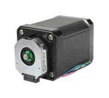 NEMA17: Stepper Motor, Applications, Features
31 March 20228915
 ESP-12E Wi-Fi Module: Pinout, Datasheet and Power
18 September 202120562
![ICL7660S Voltage Regulators DC Switching Regulators[Video]:Datasheet, Pinout, and Applications.](https://res.utmel.com/Images/Article/91a532a5-68a0-4d45-acb6-10f0b31c4052.png) ICL7660S Voltage Regulators DC Switching Regulators[Video]:Datasheet, Pinout, and Applications.
ICL7660S Voltage Regulators DC Switching Regulators[Video]:Datasheet, Pinout, and Applications.01 April 20223038
 MMBT3904LT1G NPN Transistor: Datasheet, Circuits, and Marking Diagram
20 August 20213034
 Trimmer Resistors: From Principles to Selection and Applications
11 August 20253442
 The 2026 Engineer’s Guide: Choosing the Right MCU for Your Next IoT & New Energy Project
30 April 2026944
 What is fluorescent lamp?
19 October 20214374
 What are Wire Wound Resistors?
19 January 202612279
 Discovering Optimal Materials for Wide Bandgap Semiconductors
20 January 20242180
 What is a Motor Starter?
26 December 20256181
 Comprehensive Analysis of Each Functional Circuit of Switching Power Supply
06 May 20225727
 How Electric Fuses Work: Types, Ratings, and Selection Guide
14 July 202617790
NXP Semiconductors
In Stock
United States
China
Canada
Japan
Russia
Germany
United Kingdom
Singapore
Italy
Hong Kong(China)
Taiwan(China)
France
Korea
Mexico
Netherlands
Malaysia
Austria
Spain
Switzerland
Poland
Thailand
Vietnam
India
United Arab Emirates
Afghanistan
Åland Islands
Albania
Algeria
American Samoa
Andorra
Angola
Anguilla
Antigua & Barbuda
Argentina
Armenia
Aruba
Australia
Azerbaijan
Bahamas
Bahrain
Bangladesh
Barbados
Belarus
Belgium
Belize
Benin
Bermuda
Bhutan
Bolivia
Bonaire, Sint Eustatius and Saba
Bosnia & Herzegovina
Botswana
Brazil
British Indian Ocean Territory
British Virgin Islands
Brunei
Bulgaria
Burkina Faso
Burundi
Cabo Verde
Cambodia
Cameroon
Cayman Islands
Central African Republic
Chad
Chile
Christmas Island
Cocos (Keeling) Islands
Colombia
Comoros
Congo
Congo (DRC)
Cook Islands
Costa Rica
Côte d’Ivoire
Croatia
Cuba
Curaçao
Cyprus
Czechia
Denmark
Djibouti
Dominica
Dominican Republic
Ecuador
Egypt
El Salvador
Equatorial Guinea
Eritrea
Estonia
Eswatini
Ethiopia
Falkland Islands
Faroe Islands
Fiji
Finland
French Guiana
French Polynesia
Gabon
Gambia
Georgia
Ghana
Gibraltar
Greece
Greenland
Grenada
Guadeloupe
Guam
Guatemala
Guernsey
Guinea
Guinea-Bissau
Guyana
Haiti
Honduras
Hungary
Iceland
Indonesia
Iran
Iraq
Ireland
Isle of Man
Israel
Jamaica
Jersey
Jordan
Kazakhstan
Kenya
Kiribati
Kosovo
Kuwait
Kyrgyzstan
Laos
Latvia
Lebanon
Lesotho
Liberia
Libya
Liechtenstein
Lithuania
Luxembourg
Macao(China)
Madagascar
Malawi
Maldives
Mali
Malta
Marshall Islands
Martinique
Mauritania
Mauritius
Mayotte
Micronesia
Moldova
Monaco
Mongolia
Montenegro
Montserrat
Morocco
Mozambique
Myanmar
Namibia
Nauru
Nepal
New Caledonia
New Zealand
Nicaragua
Niger
Nigeria
Niue
Norfolk Island
North Korea
North Macedonia
Northern Mariana Islands
Norway
Oman
Pakistan
Palau
Palestinian Authority
Panama
Papua New Guinea
Paraguay
Peru
Philippines
Pitcairn Islands
Portugal
Puerto Rico
Qatar
Réunion
Romania
Rwanda
Samoa
San Marino
São Tomé & Príncipe
Saudi Arabia
Senegal
Serbia
Seychelles
Sierra Leone
Sint Maarten
Slovakia
Slovenia
Solomon Islands
Somalia
South Africa
South Sudan
Sri Lanka
St Helena, Ascension, Tristan da Cunha
St. Barthélemy
St. Kitts & Nevis
St. Lucia
St. Martin
St. Pierre & Miquelon
St. Vincent & Grenadines
Sudan
Suriname
Svalbard & Jan Mayen
Sweden
Syria
Tajikistan
Tanzania
Timor-Leste
Togo
Tokelau
Tonga
Trinidad & Tobago
Tunisia
Turkey
Turkmenistan
Turks & Caicos Islands
Tuvalu
U.S. Outlying Islands
U.S. Virgin Islands
Uganda
Ukraine
Uruguay
Uzbekistan
Vanuatu
Vatican City
Venezuela
Wallis & Futuna
Yemen
Zambia
Zimbabwe
![MC9S12A128CPVE]() MC9S12A128CPVE
MC9S12A128CPVENXP USA Inc.
![DSP56F807PY80E]() DSP56F807PY80E
DSP56F807PY80ENXP USA Inc.
![MC908AZ32ACFUE]() MC908AZ32ACFUE
MC908AZ32ACFUENXP USA Inc.
![MK60FN1M0VLQ12]() MK60FN1M0VLQ12
MK60FN1M0VLQ12NXP USA Inc.
![MK66FX1M0VLQ18]() MK66FX1M0VLQ18
MK66FX1M0VLQ18NXP USA Inc.
![MC56F8037VLH]() MC56F8037VLH
MC56F8037VLHNXP USA Inc.
![MKL03Z32VFG4]() MKL03Z32VFG4
MKL03Z32VFG4NXP USA Inc.
![MC9S12A256CPVE]() MC9S12A256CPVE
MC9S12A256CPVENXP USA Inc.
![MKL25Z128VLK4]() MKL25Z128VLK4
MKL25Z128VLK4NXP USA Inc.
![MK60DN512VLL10]() MK60DN512VLL10
MK60DN512VLL10NXP USA Inc.


