

 Product
 Brand
Brand Articles
 Tools
Tools
MLCC Substitution Guide: What to Do When Your Capacitor Is on a 30-Week Lead Time
TrendForce reported that by late June 2026 the book-to-bill ratios of Murata, Samsung Electro-Mechanics and Taiyo Yuden had reached 1.30, 1.31 and 1.25, the highest since the pandemic, while Murata's orders-to-backlog ratio of 1.27 exceeded the 1.25 peak that marked the start of the 2018 shortage. Lead times on constrained high-capacitance grades are commonly reported in the 26 to 40 week range, against a historical baseline near 8 to 10 weeks.
When a component on your BOM is quoted at 26 to 40 weeks, waiting out the allocation cycle is not an option. The question is what can actually go in that footprint instead — an electrically valid alternate that fits the existing land pattern, or one that fits with minimal layout change. This article gives the engineering framework for finding it, starting with which parts on your BOM genuinely need attention.
1. BOM Triage: Which Parts Are Actually at Risk
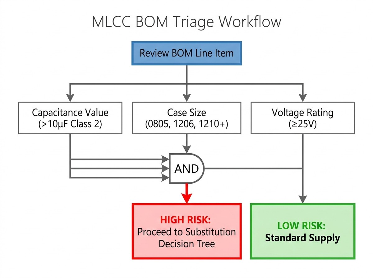
The squeeze is concentrated, not broad. Most MLCC line items on a typical board are unaffected. Before redesigning anything, isolate the parts that are genuinely constrained.
Capacitance value is the primary filter. Class 2 parts at roughly 10 µF and above are where the pressure sits, and it rises sharply above 22 µF. This single column will identify most of your exposure.
Two further columns modify that picture rather than acting as independent filters:
Case size. The core of the shortage is high-CV parts in 0805, 1206 and 1210. But do not treat small cases as automatically safe: a 10 µF part in 0603 is contested between consumer miniaturisation and server decoupling networks, both of which want the same capacitance density.
Voltage rating. Low voltage does not mean low risk. The AI server decoupling demand that is driving this cycle sits overwhelmingly in 6.3 V, 10 V and 16 V high-capacitance grades. Higher-voltage large-case parts are also tight, but for different end markets. A 100 µF 6.3 V 1210 is a textbook constrained part despite its low voltage rating.
What is reliably safe: low-capacitance commodity values — 0.1 µF and 1 µF in 0402 and 0603 — remain widely available on normal lead times. Do not spend engineering hours or allocation budget on them.
2. DC Bias Derating: Why the Printed Value Misleads
The most common substitution mistake is assuming a 10 µF reel label means 10 µF in the circuit. For Class 2 MLCCs it does not.
Class 2 dielectrics — X5R, X7R, X7S, Y5V — use barium titanate as their core material. Under an applied DC voltage the ferroelectric domains progressively align, reducing the dielectric constant available for charge storage and producing a measurable loss of capacitance[1]. Class 1 dielectrics such as C0G/NP0 do not behave this way; their capacitance stays essentially flat across the rated voltage range.
Three variables determine how much is lost:
Case size. For the same nominal value and voltage rating, a smaller case loses more capacitance than a larger one. The larger package contains more dielectric volume across which the field is distributed.
Voltage rating headroom. A part rated well above the applied rail retains more of its nominal value. Operating close to the rated voltage puts the part in the steep region of the bias curve, where a small voltage change produces a large capacitance drop.
Dielectric class. Y5V is the worst offender by a wide margin and is rarely suitable at meaningful DC bias. X5R, X7R and X7S formulations vary between manufacturers and series, but no Class 2 dielectric is immune.
Two secondary effects also differ between candidates:
Temperature coefficient. Capacitance drifts away from the 25 °C reference point. If the board runs hot or cold, read the bias curve at the operating temperature rather than the room-temperature curve.
Ageing. Class 2 dielectrics lose capacitance logarithmically over time as the crystal structure relaxes[2]. A part that has been on a shelf for months measures lower than a freshly reflowed one, and heating above the Curie point resets the clock temporarily.
The practical consequence: two parts with identical printed markings in different case sizes can differ in effective capacitance by a factor of several at the same operating voltage. A substitution validated on nominal value alone is not validated.
What to do. Open the vendor simulation tool for the specific constrained part number. Murata SimSurfing, Samsung Electro-Mechanics' component library simulator and TDK's dynamic bias models all let you enter your actual rail voltage and read effective capacitance off the C–V curve. That figure, not the reel label, is your substitution target. For background on dielectric classes and the parameters that matter, see our ceramic capacitor guide.
3. The Substitution Decision Tree
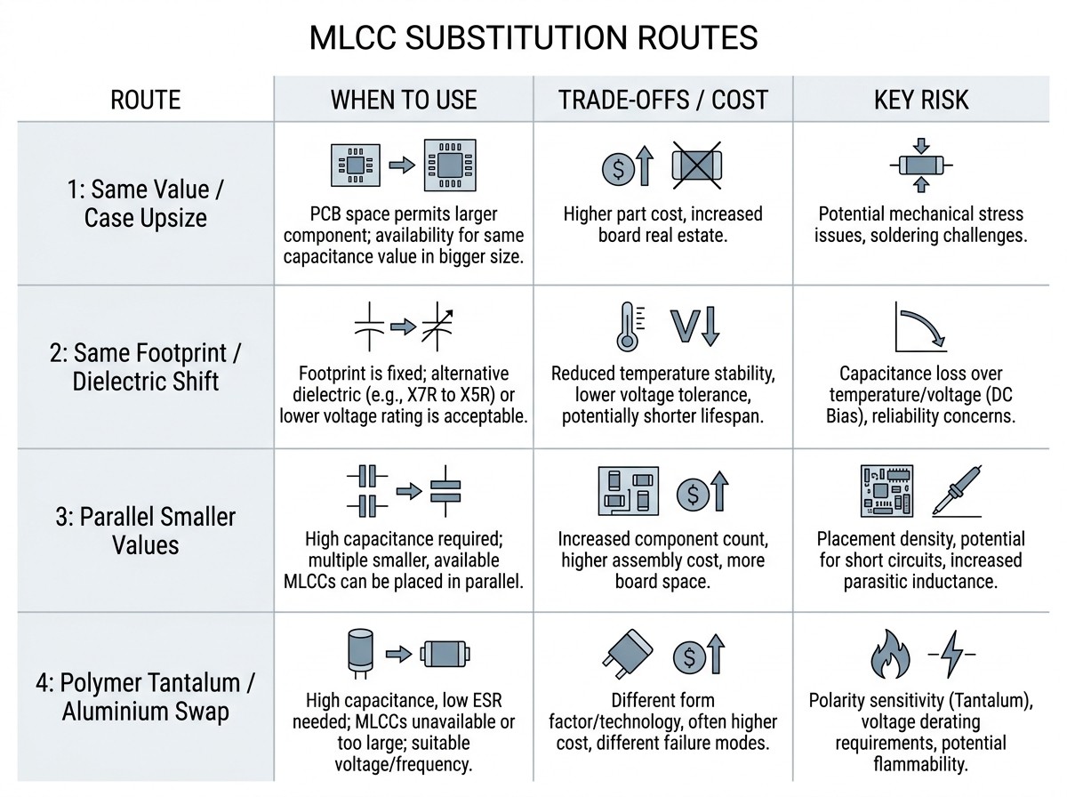
Once you know the effective capacitance the circuit actually needs at its operating voltage, there are four routes.
| Route | When to use it | What it costs | What it breaks |
|---|---|---|---|
| 1. Same value, different case size or voltage rating | A larger-case or higher-voltage equivalent is available in the same dielectric. | Board area if upsizing; effective capacitance if downsizing; higher unit cost for over-rated voltage parts. | A smaller case reduces retained capacitance under bias, so re-read the derating curve. A larger case raises flex-crack susceptibility — see Section 5. Raising the voltage rating is often the cheapest way to recover effective capacitance without changing footprint. |
| 2. Same footprint, different dielectric | X5R is constrained but X7R or X7S is available in the same case and value. | Temperature-coefficient range and bias behaviour both shift. | X7R covers a wider temperature band, but its retention under bias may differ from the X5R at your voltage — verify on the vendor curve rather than assuming an upgrade. X7S carries further trade-offs in thermally demanding designs; see our guide to Class 2 MLCCs in liquid-cooled systems. |
| 3. Parallel bank of smaller values | No single replacement fits the footprint or is available. | Board area and placement count both rise, often more than expected. | Each candidate must be derated before counting, and the required count is usually higher than naive division suggests. ESR falls and mounted inductance improves, but the area and placement cost is real. See Section 4. |
| 4. Different technology entirely | No MLCC route works, and polymer tantalum or polymer aluminium fits the space. | Higher ESR, greater height, different failure mode, and a separate supply situation of its own. | Polymer capacitors do not suffer DC bias capacitance loss, but their impedance profile is different[3], so a switching converter's control loop will respond differently. This is not a drop-in. Standard practice is to parallel the polymer with a commodity ceramic to handle high-frequency switching noise. |
4. The Paralleling Math and Anti-Resonance
Replacing one large MLCC with a bank of smaller ones is the most common route when the original is simply unavailable. Naive division fails, because the smaller parts derate too — and usually harder than the part you are replacing.
Worked example. The figures below are illustrative, chosen to show the shape of the calculation. Pull your own numbers from the manufacturer's C–V curve for the specific part numbers you are considering; derating varies significantly between manufacturers and series even at identical ratings.
The constrained part is a 100 µF, 6.3 V, X5R, 1210 operating at a 5 V rail — a typical bulk decoupling position and a grade squarely inside the current shortage. The candidate replacement is a 22 µF, 6.3 V, X5R, 0805.
| Step | Value (illustrative) |
|---|---|
| Original part, nominal | 100 µF (6.3 V, 1210) |
| Original part, effective at 5 V bias | approx. 30 µF — this is the real design target |
| Candidate, nominal | 22 µF (6.3 V, 0805) |
| Candidate, effective at 5 V bias | approx. 4.4 µF — smaller case, same voltage rating, so it derates harder |
| Naive count (100 ÷ 22, nominal against nominal) | 5 pcs |
| Correct count (30 ÷ 4.4, effective against effective) | 7 pcs |
| Board area | 7 × 0805 occupies roughly twice the area of one 1210, before placement clearances |
| ESR | Falls substantially — helps ripple, but reduces damping in loops that relied on it |
| Mounted inductance | Improves if the parts are distributed; much less so if crowded onto one node |
The naive answer of five parts leaves the circuit roughly 30 percent short of its original effective capacitance. Both sides of the division have to be derated, or the arithmetic is meaningless.
Note also how the routes interact. Had the candidate been a 22 µF part rated at 10 V rather than 6.3 V, the extra headroom would have improved its retention at the same 5 V rail and reduced the count — trading unit cost against board area and placement time. Check both options before committing.
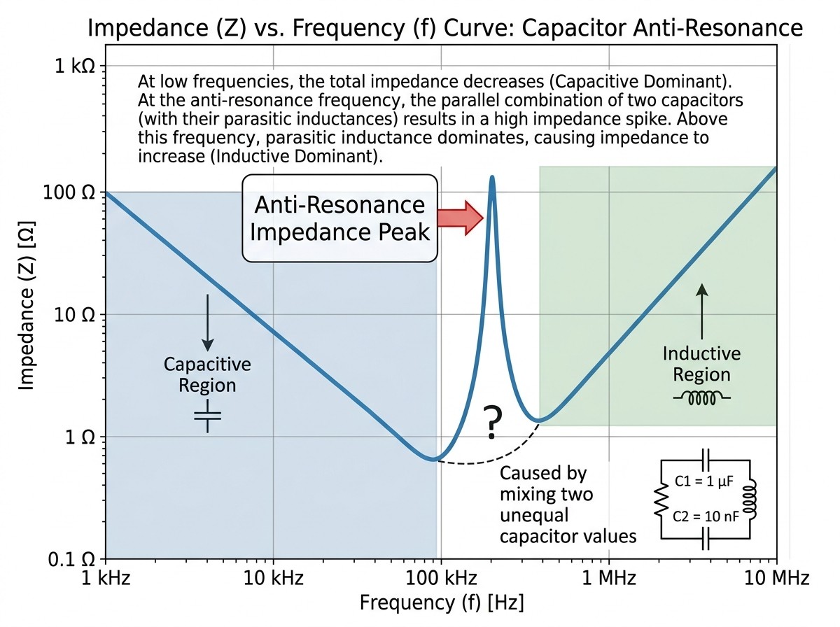
Anti-resonance, and when the usual advice applies. When two capacitors of very different value sit in parallel, an impedance peak can appear at the frequency where one has turned inductive while the other is still capacitive. At that frequency the bank performs worse, not better. Two situations call for opposite responses:
Replacing one part with a bank in the same position. Populate it with identical parts — same value, same case size, same series. You are substituting a single component, and introducing a spread of values creates a resonance behaviour the original design never had.
Designing a board-level power delivery network. Here a deliberate spread across several decades of capacitance is the standard approach, because a single value produces a deep impedance null at one frequency and higher impedance everywhere else. Anti-resonance is managed by keeping the ratio between adjacent value groups modest, commonly within about a decade, and by relying on ESR for damping — not by collapsing the design onto one part number. Our article on AI server capacitor counts covers the scale at which this is now being done.
The point-of-load warning. Paralleling is straightforward for bulk decoupling where some layout flexibility exists. It is much harder near a high-current point-of-load, where placement and loop inductance dominate and there may simply be no room for seven parts where one used to sit. In those positions a polymer capacitor paralleled with a commodity ceramic is often the more practical route — but re-verify converter stability, because the control loop will see a different impedance profile.
MLCC capacitor derating, explained
5. When a Substitution Needs Requalification, Not Just a BOM Edit
A paper swap is safe only in non-critical positions. Change any of the following and the part needs re-testing:
Board-flex risk. Larger cases crack more readily under board bending because the ceramic body spans a wider area. If you up-size a part that sits near a mounting hole, connector, edge guide or depanel line, specify a soft-termination variant — the conductive resin layer absorbs mechanical stress that would otherwise reach the ceramic.
AEC-Q200 status. Qualification does not transfer between manufacturers or between series within one manufacturer. An automotive position needs a substitute carrying its own certification.
Safety-certified positions. Capacitors bridging an isolation barrier cannot be substituted on parametric equivalence. These positions are governed by safety certification, not by datasheet comparison.
Timing and filter circuits. Any capacitor that sets a time constant, filter corner or precision cutoff must be re-verified against actual effective capacitance. A nominal match proves nothing here.
Rule of thumb: bulk decoupling away from flex points is generally safe to swap once effective capacitance is confirmed. Anything touching regulation, precision timing, safety isolation or mechanical stress needs requalification.
6. Counterfeit Risk During Allocation
Long lead times push buying pressure toward non-authorised channels, and MLCCs are among the hardest components to authenticate visually — most carry no markings at all, and the smaller case sizes carry none by construction. Three checks are worth running:
Date code and packaging. Ask for the date code lot and confirm packaging integrity before purchase. Reels from unknown channels frequently lack factory traceability.
Capacitance and dissipation factor under bias. Measure an incoming sample at the same DC bias as your circuit and compare against the manufacturer's published C–V curve. An inferior dielectric shows a different loss characteristic even when the nominal value looks right.
Price sanity check. An offer on a constrained grade priced near pre-shortage levels is not a lucky find. Treat it as a warning.
For the wider supply dynamics behind these risks, see our 2026 passive components market update.
7. The MLCC Substitution Checklist
Run this against a single at-risk part number:
[ ] Confirm the part is genuinely constrained — start with capacitance value, then check case size and voltage rating.
[ ] Read effective capacitance off the vendor C–V curve at your actual operating voltage. This is your target, not the reel label.
[ ] Pick a route from the decision tree in Section 3.
[ ] For a different case size or voltage rating, re-read the alternate's derating curve rather than assuming equivalence.
[ ] For a parallel bank, derate both sides before dividing, and populate the bank with identical parts.
[ ] For a polymer alternate, add a parallel commodity ceramic and schedule converter stability verification.
[ ] If the case size increased, assess flex-crack exposure and consider a soft-termination variant.
[ ] If AEC-Q200 is required, confirm the substitute holds its own certification.
[ ] If the capacitor sits in a filter, timing or safety-isolation position, schedule requalification.
[ ] Source through authorised channels and run incoming capacitance and dissipation-factor checks against the vendor curve.
Quick Answers to Frequent Substitution Questions
Can I replace a 10 µF MLCC with a polymer tantalum of the same value?
Not as a drop-in. The polymer part has higher ESR and a different impedance profile, which can change the stability of a switching converter. Verify the circuit response, and parallel the polymer with a low-value ceramic to suppress high-frequency noise.
Why does the same nominal value behave differently in different case sizes?
DC bias loss depends on dielectric volume. A larger case distributes the applied field across more material, so it retains a higher percentage of its nominal capacitance at the same bias voltage than a smaller case of the same rating.
How do I know whether a substitute needs soft termination?
If the replacement is physically larger than the original and the board can flex — near connectors, mounting holes, edge guides or depanel lines — choose a soft-termination version. Moderate board bending is enough to crack a standard ceramic body.
Are low-capacitance commodity parts safe to ignore?
Broadly yes. Values of a few microfarads or less in 0402 and 0603 remain widely available on normal lead times. Note the exception: high-capacitance parts in small cases, such as 10 µF in 0603, are contested and should not be assumed safe on case size alone.
Where can I source alternate MLCCs and polymer capacitors in small quantities?
Search across manufacturers by case size, dielectric and voltage rating on Utmel's component catalog, which carries Murata, Samsung Electro-Mechanics, TDK, Taiyo Yuden, Yageo and Walsin stock from single pieces to full reels — enough to evaluate a substitution before committing the BOM change.
References
Does the capacitance change when a DC voltage is applied? — Murata
MLCC DC bias and ageing capacitance loss explained — Passive Components Blog
MLCC alternatives: polymer capacitors versus MLCCs — Avnet Abacus
 UTMEL
UTMEL
We are the professional distributor of electronic components, providing a large variety of products to save you a lot of time, effort, and cost with our efficient self-customized service. careful order preparation fast delivery service
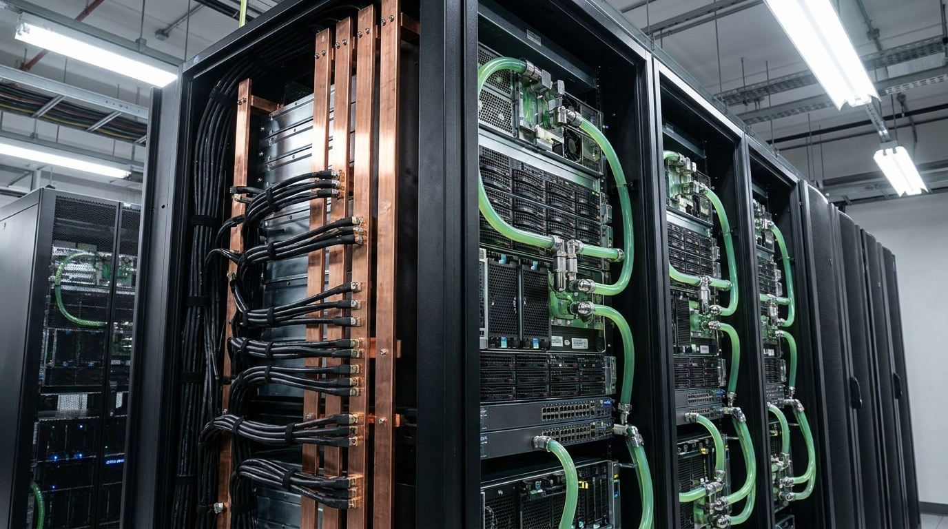 AI Server MLCCs: Why NVIDIA Rubin Racks Require Over 600,000 CapacitorsUTMEL02 June 20263293
Next-generation AI servers like NVIDIA's Rubin architecture require over 600,000 MLCCs per rack due to extreme power densities exceeding 120kW. This transition from GB300 demands high-capacitance, low-ESR capacitors with X7R/X7S dielectrics to handle intense transient responses and thermal loads, forcing procurement teams to navigate extended 24-week lead times for these specialized components.
Read More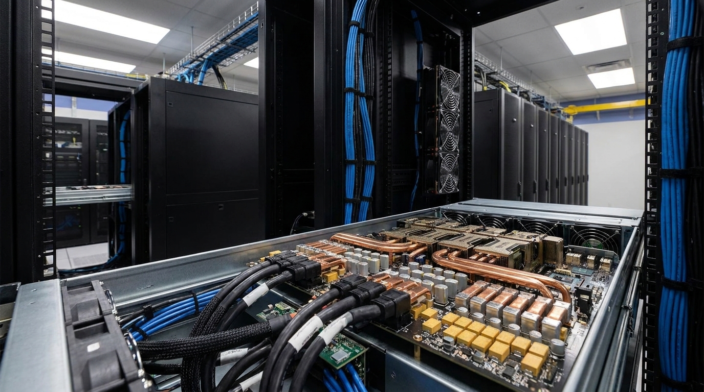 MLCC vs Polymer Tantalum Capacitors: Overcoming 2026 Shortages in AI Server PDNsUTMEL07 August 2026618
Facing 2026 MLCC lead times of up to 24 weeks driven by AI server demand, hardware engineers are substituting multi-layer ceramic capacitors with conductive polymer tantalum capacitors. While Class II MLCCs suffer severe DC bias capacitance loss and acoustic noise, polymer tantalums offer voltage stability and low ESR. Implementing a division-of-labor strategy—using polymer tantalums for bulk decoupling and MLCCs for point-of-load—optimizes PDN performance and bypasses supply bottlenecks.
Read More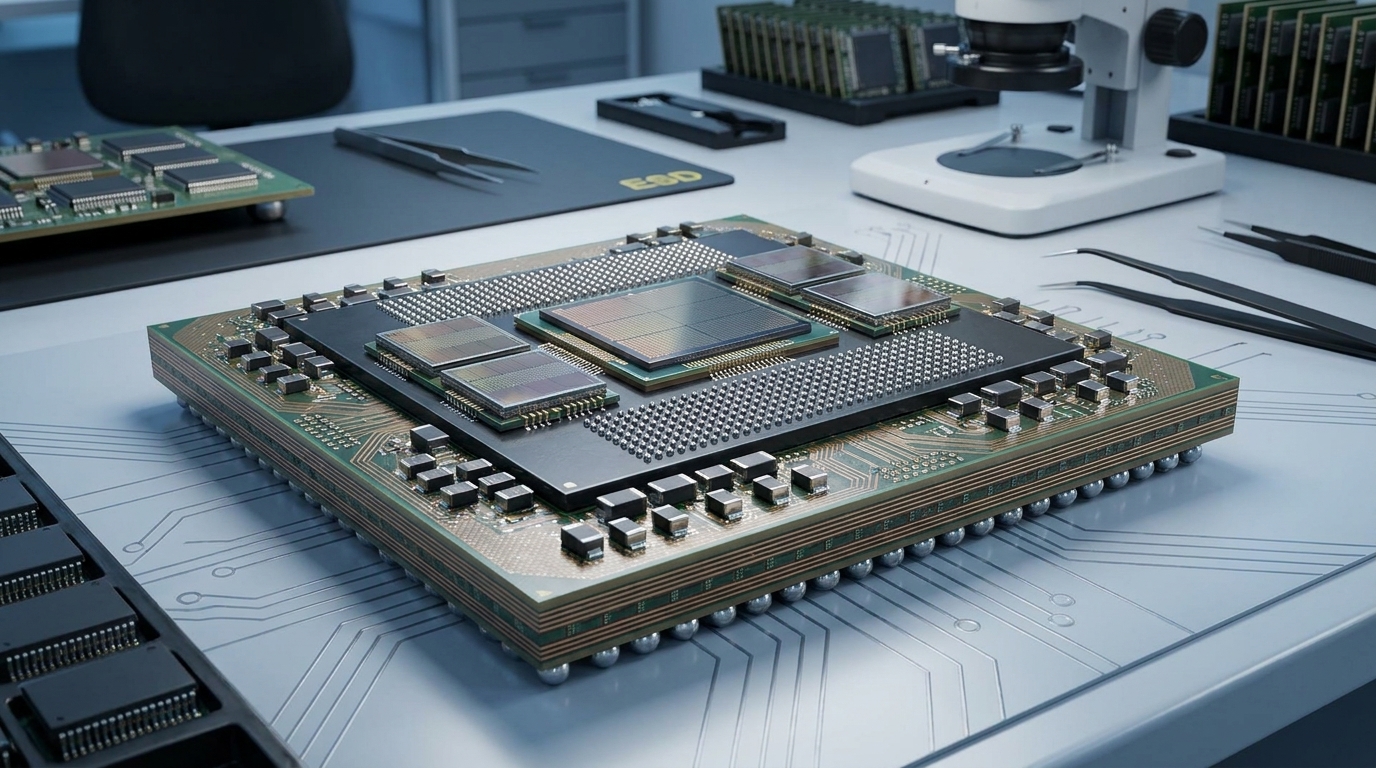 Sourcing Silicon Capacitors and MLCCs in the AI Hardware EraUTMEL13 August 2026552
Modern AI hardware requires a hybrid Power Delivery Network (PDN) to maintain low-voltage stability under extreme transient currents. Deep Trench Silicon Capacitors (DTCs) integrate directly into advanced packages to deliver ultra-low ESL and stable performance for high-frequency transient suppression. Meanwhile, Multilayer Ceramic Capacitors (MLCCs) provide essential bulk energy storage on the motherboard, making both technologies complementary across the AI power stack.
Read More MLCC DC Bias Derating: How to Calculate and Compare Effective Capacitance Before Component SelectionUTMEL11 September 2026145
Class II ceramic capacitors suffer significant capacitance loss under DC voltage due to ferroelectric domain saturation and high electric field intensity. This comprehensive engineering guide explains how to calculate true worst-case effective capacitance by compounding DC bias, temperature, tolerance, and aging. It provides multi-vendor simulation workflows, benchtop impedance measurement techniques, and practical guidelines to maintain power supply stability and avoid costly design failures.
Read More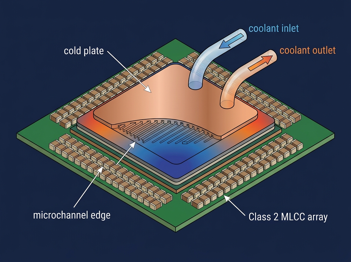 Thermal Management in AI Servers: Specifying Class 2 MLCCs (X7R/X7S) for Liquid Cooling EnvironmentsUTMEL13 July 2026340
Explore how the transition from traditional air-cooling to liquid cooling (direct-to-chip and immersion) in high-density AI server racks alters component thermal profiles. Focus on why design engineers are increasingly specifying Class 2 MLCCs (X7R and X7S dielectrics) over standard X5R variants to prevent thermal degradation near the liquid cooling microchannels. Explain how these capacitors mitigate acoustic noise and voltage bias degradation under heavy workloads. Provide sourcing advice for high-reliability passives via UTMEL during this high-demand memory and passive component super-cycle.
Read More
Subscribe to Utmel !
![NCP1615AIOGEVB]() NCP1615AIOGEVB
NCP1615AIOGEVBonsemi
![PCA8561AHN-ARD]() PCA8561AHN-ARD
PCA8561AHN-ARDNXP USA Inc.
![5587]() 5587
5587Adafruit Industries LLC
![LMR51430EVM]() LMR51430EVM
LMR51430EVMTexas Instruments
![CDCBT1001EVM]() CDCBT1001EVM
CDCBT1001EVMTexas Instruments
![MCXLEVK-H055BBB-I]() MCXLEVK-H055BBB-I
MCXLEVK-H055BBB-IARIES Embedded
![FRDM-STBA-A8967]() FRDM-STBA-A8967
FRDM-STBA-A8967NXP USA Inc.
![PSSN-B256-LIFCL]() PSSN-B256-LIFCL
PSSN-B256-LIFCLLattice Semiconductor Corporation
![EVL400W-80PL]() EVL400W-80PL
EVL400W-80PLSTMicroelectronics
![IQS7211AEV02A-S]() IQS7211AEV02A-S
IQS7211AEV02A-SAzoteq (Pty) Ltd
