
 Product
 Brand
Brand Articles
 Tools
Tools
23LCV512 SPI Serial SRAM: Pinout, Equivalent and Datasheet


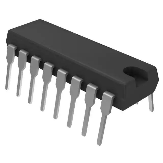
Memory IC 23LCV512 4.4mm mm
The Microchip Technology Inc. 23LCV512 is a 512 Kbit Serial SRAM device. The memory is accessed via a simple Serial Peripheral Interface (SPI) compatible serial bus. The bus signals required are a clock input (SCK) plus separate data in (SI) and data out (SO) lines. Furthermore, Huge range of Semiconductors, Capacitors, Resistors and IcS in stock. Welcome RFQ.

SRAM vs DRAM : How SRAM Works? How DRAM Works? Why SRAM is faster than DRAM?
23LCV512 Pinout
The following figure is the diagram of 23LCV512 Pinout.

Pinout
23LCV512 CAD Model
The following figure is the diagram of 23LCV512 Footprint.

Footprint
23LCV512 Description
The Microchip Technology Inc. 23LCV512 is a 512 Kbit Serial SRAM device. The memory is accessed via a simple Serial Peripheral Interface (SPI) compatible serial bus. The bus signals required are a clock input (SCK) plus separate data in (SI) and data out (SO) lines. Access to the device is controlled through a Chip Select (CS) input. Additionally, SDI (Serial Dual Interface) is supported if your application needs faster data rates. This device also supports unlimited reads and writes to the memory array, and supports data backup via external battery/coin cell connected to VBAT. The 23LCV512 is available in standard packages including 8-lead SOIC, PDIP and advanced 8-lead TSSOP. The 23LCV512 features an internal switch that will maintain the SRAM contents.
This article provides you with a basic overview of the 23LCV512 SPI Serial SRAM, including its pin descriptions, features and specifications, etc., to help you quickly understand what 23LCV512 is.
23LCV512 Features
● SPI-Compatible Bus Interface:
◆ 20 MHz Clock rate
◆ SPI/SDI mode
● Low-Power CMOS Technology:
◆ Read Current: 3 mA at 5.5V, 20 MHz
◆ Standby Current: 4 μA at +85°C
● Unlimited Read and Write Cycles
● External Battery Backup support
● Zero Write Time
● 64K x 8-bit Organization:
◆ 32-byte page
● Byte, Page and Sequential mode for Reads and Writes
● High Reliability
● Temperature Range Supported:
◆ Industrial (I): -40°C to +85°C
● Pb-Free and RoHS Compliant, Halogen Free.
● 8-Lead SOIC, TSSOP and PDIP Packages
Specifications
- TypeParameter
- Factory Lead Time6 Weeks
- Mounting Type
The "Mounting Type" in electronic components refers to the method used to attach or connect a component to a circuit board or other substrate, such as through-hole, surface-mount, or panel mount.
Surface Mount - Package / Case
refers to the protective housing that encases an electronic component, providing mechanical support, electrical connections, and thermal management.
8-TSSOP (0.173, 4.40mm Width) - Surface Mount
having leads that are designed to be soldered on the side of a circuit board that the body of the component is mounted on.
YES - Memory TypesNon-Volatile
- Usage LevelAutomotive grade
- Operating Temperature
The operating temperature is the range of ambient temperature within which a power supply, or any other electrical equipment, operate in. This ranges from a minimum operating temperature, to a peak or maximum operating temperature, outside which, the power supply may fail.
-40°C~85°C TA - Packaging
Semiconductor package is a carrier / shell used to contain and cover one or more semiconductor components or integrated circuits. The material of the shell can be metal, plastic, glass or ceramic.
Tape & Reel (TR) - Published2012
- JESD-609 Code
The "JESD-609 Code" in electronic components refers to a standardized marking code that indicates the lead-free solder composition and finish of electronic components for compliance with environmental regulations.
e3 - Part Status
Parts can have many statuses as they progress through the configuration, analysis, review, and approval stages.
Active - Moisture Sensitivity Level (MSL)
Moisture Sensitivity Level (MSL) is a standardized rating that indicates the susceptibility of electronic components, particularly semiconductors, to moisture-induced damage during storage and the soldering process, defining the allowable exposure time to ambient conditions before they require special handling or baking to prevent failures
1 (Unlimited) - Number of Terminations8
- Terminal Finish
Terminal Finish refers to the surface treatment applied to the terminals or leads of electronic components to enhance their performance and longevity. It can improve solderability, corrosion resistance, and overall reliability of the connection in electronic assemblies. Common finishes include nickel, gold, and tin, each possessing distinct properties suitable for various applications. The choice of terminal finish can significantly impact the durability and effectiveness of electronic devices.
Matte Tin (Sn) - annealed - Voltage - Supply
Voltage - Supply refers to the range of voltage levels that an electronic component or circuit is designed to operate with. It indicates the minimum and maximum supply voltage that can be applied for the device to function properly. Providing supply voltages outside this range can lead to malfunction, damage, or reduced performance. This parameter is critical for ensuring compatibility between different components in a circuit.
2.5V~5.5V - Peak Reflow Temperature (Cel)
Peak Reflow Temperature (Cel) is a parameter that specifies the maximum temperature at which an electronic component can be exposed during the reflow soldering process. Reflow soldering is a common method used to attach electronic components to a circuit board. The Peak Reflow Temperature is crucial because it ensures that the component is not damaged or degraded during the soldering process. Exceeding the specified Peak Reflow Temperature can lead to issues such as component failure, reduced performance, or even permanent damage to the component. It is important for manufacturers and assemblers to adhere to the recommended Peak Reflow Temperature to ensure the reliability and functionality of the electronic components.
260 - Number of Functions1
- Terminal Pitch
The center distance from one pole to the next.
0.65mm - Time@Peak Reflow Temperature-Max (s)
Time@Peak Reflow Temperature-Max (s) refers to the maximum duration that an electronic component can be exposed to the peak reflow temperature during the soldering process, which is crucial for ensuring reliable solder joint formation without damaging the component.
40 - Base Part Number
The "Base Part Number" (BPN) in electronic components serves a similar purpose to the "Base Product Number." It refers to the primary identifier for a component that captures the essential characteristics shared by a group of similar components. The BPN provides a fundamental way to reference a family or series of components without specifying all the variations and specific details.
23LCV512 - JESD-30 Code
JESD-30 Code refers to a standardized descriptive designation system established by JEDEC for semiconductor-device packages. This system provides a systematic method for generating designators that convey essential information about the package's physical characteristics, such as size and shape, which aids in component identification and selection. By using JESD-30 codes, manufacturers and engineers can ensure consistency and clarity in the specification of semiconductor packages across various applications and industries.
R-PDSO-G8 - Supply Voltage-Max (Vsup)
The parameter "Supply Voltage-Max (Vsup)" in electronic components refers to the maximum voltage that can be safely applied to the component without causing damage. It is an important specification to consider when designing or using electronic circuits to ensure the component operates within its safe operating limits. Exceeding the maximum supply voltage can lead to overheating, component failure, or even permanent damage. It is crucial to adhere to the specified maximum supply voltage to ensure the reliable and safe operation of the electronic component.
5.5V - Supply Voltage-Min (Vsup)
The parameter "Supply Voltage-Min (Vsup)" in electronic components refers to the minimum voltage level required for the component to operate within its specified performance range. This parameter indicates the lowest voltage that can be safely applied to the component without risking damage or malfunction. It is crucial to ensure that the supply voltage provided to the component meets or exceeds this minimum value to ensure proper functionality and reliability. Failure to adhere to the specified minimum supply voltage may result in erratic behavior, reduced performance, or even permanent damage to the component.
2.5V - Interface
In electronic components, the term "Interface" refers to the point at which two different systems, devices, or components connect and interact with each other. It can involve physical connections such as ports, connectors, or cables, as well as communication protocols and standards that facilitate the exchange of data or signals between the connected entities. The interface serves as a bridge that enables seamless communication and interoperability between different parts of a system or between different systems altogether. Designing a reliable and efficient interface is crucial in ensuring proper functionality and performance of electronic components and systems.
SPI, Serial - Memory Size
The memory capacity is the amount of data a device can store at any given time in its memory.
512Kb 64K x 8 - Operating Mode
A phase of operation during the operation and maintenance stages of the life cycle of a facility.
SYNCHRONOUS - Clock Frequency
Clock frequency, also known as clock speed, refers to the rate at which a processor or electronic component can execute instructions. It is measured in hertz (Hz) and represents the number of cycles per second that the component can perform. A higher clock frequency typically indicates a faster processing speed and better performance. However, it is important to note that other factors such as architecture, efficiency, and workload also play a significant role in determining the overall performance of a component. In summary, clock frequency is a crucial parameter that influences the speed and efficiency of electronic components in processing data and executing tasks.
20MHz - Memory Format
Memory Format in electronic components refers to the specific organization and structure of data storage within a memory device. It defines how data is stored, accessed, and managed within the memory module. Different memory formats include RAM (Random Access Memory), ROM (Read-Only Memory), and various types of flash memory. The memory format determines the speed, capacity, and functionality of the memory device, and it is crucial for compatibility with other components in a system. Understanding the memory format is essential for selecting the right memory module for a particular application or device.
NVSRAM - Memory Interface
An external memory interface is a bus protocol for communication from an integrated circuit, such as a microprocessor, to an external memory device located on a circuit board.
SPI - Dual I/O - Organization
In the context of electronic components, the parameter "Organization" typically refers to the arrangement or structure of the internal components within a device or system. It can describe how various elements such as transistors, resistors, capacitors, and other components are physically arranged and interconnected on a circuit board or within a semiconductor chip.The organization of electronic components plays a crucial role in determining the functionality, performance, and efficiency of a device. It can impact factors such as signal propagation, power consumption, thermal management, and overall system complexity. Engineers carefully design the organization of components to optimize the operation of electronic devices and ensure reliable performance.Different types of electronic components may have specific organizational requirements based on the intended application and design considerations. For example, integrated circuits may have a highly compact and intricate organization to maximize functionality within a small footprint, while larger electronic systems may have a more modular and distributed organization to facilitate maintenance and scalability.
64KX8 - Memory Width
Memory width refers to the number of bits that can be read or written to memory at one time. It is an important specification in electronic components, particularly in memory devices like RAM and cache. A wider memory width allows for greater data throughput, enabling faster performance as more data can be processed simultaneously. Memory width can vary among different types of memory and can impact both the complexity and efficiency of data handling within electronic systems.
8 - Memory Density
Memory density in electronic components refers to the amount of data that can be stored in a given physical space or memory module. It is typically measured in bits or bytes per unit area, such as bits per square inch. Higher memory density means that more data can be stored in a smaller space, which is important for devices with limited physical size or power constraints. Memory density is a key factor in determining the capacity and performance of memory devices, such as RAM, ROM, and flash memory, and is a critical consideration in the design and manufacturing of electronic products.
524288 bit - Screening Level
In electronic components, the term "Screening Level" refers to the level of testing and inspection that a component undergoes to ensure its reliability and performance. This process involves subjecting the component to various tests, such as temperature cycling, burn-in, and electrical testing, to identify any defects or weaknesses that could affect its functionality. The screening level is typically determined based on the application requirements and the criticality of the component in the system. Components that undergo higher screening levels are generally more reliable but may also be more expensive. Overall, the screening level helps to ensure that electronic components meet the necessary quality standards for their intended use.
TS 16949 - Length4.4mm
- Height Seated (Max)
Height Seated (Max) is a parameter in electronic components that refers to the maximum allowable height of the component when it is properly seated or installed on a circuit board or within an enclosure. This specification is crucial for ensuring proper fit and alignment within the overall system design. Exceeding the maximum seated height can lead to mechanical interference, electrical shorts, or other issues that may impact the performance and reliability of the electronic device. Manufacturers provide this information to help designers and engineers select components that will fit within the designated space and function correctly in the intended application.
1.2mm - Width3mm
- RoHS Status
RoHS means “Restriction of Certain Hazardous Substances” in the “Hazardous Substances Directive” in electrical and electronic equipment.
ROHS3 Compliant
23LCV512 Equivalent
| Model number | Manufacturer | Description |
| 23LCV512-I/ST | Microchip Technology Inc | STANDARD SRAM |
| 23LCV512-I/P | Microchip Technology Inc | STANDARD SRAM |
| 23LC512T-E/ST | Microchip Technology Inc | STANDARD SRAM |
| 23LC512-E/ST | Microchip Technology Inc | STANDARD SRAM |
| N01S830BAT22ET | On Semiconductor | Serial SRAM Memory, 1 Mb, Ultra-Low-Power, 2.5 to 5.5 V TSSOP-8 (Automotive) 3000 Units/ Tape & Reel, 3000-REEL |
| 23LC512T-I/ST | Microchip Technology Inc | STANDARD SRAM |
| N01S830BAT22E | On Semiconductor | Serial SRAM Memory, 1 Mb, Ultra-Low-Power, 2.5 to 5.5 V TSSOP-8 (Automotive) 100 Units/Tube, 100-TUBE |
| 23LC512T-I/SN | Microchip Technology Inc | STANDARD SRAM |
| 23LC512-I/ST | Microchip Technology Inc | STANDARD SRAM |
Parts with Similar Specs
- ImagePart NumberManufacturerPackage / CaseMemory TypeInterfaceRoHS StatusTime@Peak Reflow Temperature-Max (s)Mounting TypePeak Reflow Temperature (Cel)Memory WidthView Compare
![23LCV512T-I/ST]()
23LCV512T-I/ST
8-TSSOP (0.173, 4.40mm Width)
Non-Volatile
SPI, Serial
ROHS3 Compliant
40
Surface Mount
260
8
![AS6C6264-55STCN]()
28-TSSOP (0.465, 11.80mm Width)
Volatile
-
ROHS3 Compliant
40
Surface Mount
260
8
![AS6C62256-55STIN]()
28-TSSOP (0.465, 11.80mm Width)
Volatile
-
ROHS3 Compliant
40
Surface Mount
260
8
![AS6C62256-55STCN]()
28-TSSOP (0.465, 11.80mm Width)
Volatile
-
ROHS3 Compliant
40
Surface Mount
260
8
![IS61C256AL-12TLI-TR]()
28-TSSOP (0.465, 11.80mm Width)
Volatile
-
ROHS3 Compliant
40
Surface Mount
260
8


23LCV512 Package
The following diagrams show the 23LCV512 Package.

View A

View B

View C
23LCV512 Package Marking Information
The following diagram shows the 23LCV512 Package Marking Information.

8-Lead TSSOP

Example
23LCV512 Recommended Land Pattern
The following is the Recommended Land Pattern of 23LCV512.

Recommended Land Pattern
23LCV512 Manufacturer
Microchip Technology Inc. is a leading provider of microcontroller and analog semiconductors, providing low-risk product development, lower total system cost and faster time to market for thousands of diverse customer applications worldwide. Headquartered in Chandler, Arizona, Microchip offers outstanding technical support along with dependable delivery and quality.
Datasheet PDF
- Datasheets :
- PCN Packaging :
- ConflictMineralStatement :
How many pins of 23LCV512T-I/ST?
8 Pins.
What’s the operating temperature of 23LCV512T-I/ST?
-40°C~85°C TA.
What is the essential property of the 23LCV512?
The Microchip Technology Inc. 23LCV512 is a 512 Kbit Serial SRAM device. The memory is accessed via a simple Serial Peripheral Interface (SPI) compatible serial bus.
What is the purpose of the 23LCV512?
The 23LCV512 is an 512 Kbit Serial SRAM designed to interface directly with the Serial Peripheral Interface (SPI) port of many of today’s popular microcontroller families, including Microchip’s PIC® microcontrollers.
 TL074 Operational Amplifier Design Guide: JFET-Input Audio & Industrial Applications
19 January 20261398
 Introduction to Microchip dsPIC33EP32MC202TESS
29 February 2024139
 74HC595N Shift Register: Pinout, Datasheet, and Functional Logic Diagram
27 August 202116109
 INA128 Amplifier: Pinout, Equivalent and Datasheet
01 November 202112605
![CR1616 vs CR2025[Video+FAQ]: Differences and Similarities](https://res.utmel.com/Images/Article/d3326313-95c7-432b-8e03-693b4d48d556.jpg) CR1616 vs CR2025[Video+FAQ]: Differences and Similarities
CR1616 vs CR2025[Video+FAQ]: Differences and Similarities21 April 202213540
 Texas Instruments MSP430F1610IPM Datasheet: Features, Applications, and Reference Designs
29 February 2024142
 STM32F103RCT6 Microcontroller: 72MHz, 64-LQFP, Pinout and Datasheet
07 February 20228677
 TL071 OP-AMP: Where & How to Use TL071?
16 November 202120829
 Introduction to Step-up Transformer
01 March 20216527
 What is Mouse in Computer?
14 February 20226395
 MLCC Substitution Guide: What to Do When Your Capacitor Is on a 30-Week Lead Time
31 July 202665
 Understanding Machine Vision and Visual Sensor
27 September 20212217
 What is ToF Technology?
22 January 20213546
 Wireless Charging Explained: Working and Standards
26 May 202110709
 IOT-Based Anti-theft Handbag
29 August 20238056
 Introduction to UFS (Universal Flash Storage)
23 July 20218610
Microchip Technology
In Stock
United States
China
Canada
Japan
Russia
Germany
United Kingdom
Singapore
Italy
Hong Kong(China)
Taiwan(China)
France
Korea
Mexico
Netherlands
Malaysia
Austria
Spain
Switzerland
Poland
Thailand
Vietnam
India
United Arab Emirates
Afghanistan
Åland Islands
Albania
Algeria
American Samoa
Andorra
Angola
Anguilla
Antigua & Barbuda
Argentina
Armenia
Aruba
Australia
Azerbaijan
Bahamas
Bahrain
Bangladesh
Barbados
Belarus
Belgium
Belize
Benin
Bermuda
Bhutan
Bolivia
Bonaire, Sint Eustatius and Saba
Bosnia & Herzegovina
Botswana
Brazil
British Indian Ocean Territory
British Virgin Islands
Brunei
Bulgaria
Burkina Faso
Burundi
Cabo Verde
Cambodia
Cameroon
Cayman Islands
Central African Republic
Chad
Chile
Christmas Island
Cocos (Keeling) Islands
Colombia
Comoros
Congo
Congo (DRC)
Cook Islands
Costa Rica
Côte d’Ivoire
Croatia
Cuba
Curaçao
Cyprus
Czechia
Denmark
Djibouti
Dominica
Dominican Republic
Ecuador
Egypt
El Salvador
Equatorial Guinea
Eritrea
Estonia
Eswatini
Ethiopia
Falkland Islands
Faroe Islands
Fiji
Finland
French Guiana
French Polynesia
Gabon
Gambia
Georgia
Ghana
Gibraltar
Greece
Greenland
Grenada
Guadeloupe
Guam
Guatemala
Guernsey
Guinea
Guinea-Bissau
Guyana
Haiti
Honduras
Hungary
Iceland
Indonesia
Iran
Iraq
Ireland
Isle of Man
Israel
Jamaica
Jersey
Jordan
Kazakhstan
Kenya
Kiribati
Kosovo
Kuwait
Kyrgyzstan
Laos
Latvia
Lebanon
Lesotho
Liberia
Libya
Liechtenstein
Lithuania
Luxembourg
Macao(China)
Madagascar
Malawi
Maldives
Mali
Malta
Marshall Islands
Martinique
Mauritania
Mauritius
Mayotte
Micronesia
Moldova
Monaco
Mongolia
Montenegro
Montserrat
Morocco
Mozambique
Myanmar
Namibia
Nauru
Nepal
New Caledonia
New Zealand
Nicaragua
Niger
Nigeria
Niue
Norfolk Island
North Korea
North Macedonia
Northern Mariana Islands
Norway
Oman
Pakistan
Palau
Palestinian Authority
Panama
Papua New Guinea
Paraguay
Peru
Philippines
Pitcairn Islands
Portugal
Puerto Rico
Qatar
Réunion
Romania
Rwanda
Samoa
San Marino
São Tomé & Príncipe
Saudi Arabia
Senegal
Serbia
Seychelles
Sierra Leone
Sint Maarten
Slovakia
Slovenia
Solomon Islands
Somalia
South Africa
South Sudan
Sri Lanka
St Helena, Ascension, Tristan da Cunha
St. Barthélemy
St. Kitts & Nevis
St. Lucia
St. Martin
St. Pierre & Miquelon
St. Vincent & Grenadines
Sudan
Suriname
Svalbard & Jan Mayen
Sweden
Syria
Tajikistan
Tanzania
Timor-Leste
Togo
Tokelau
Tonga
Trinidad & Tobago
Tunisia
Turkey
Turkmenistan
Turks & Caicos Islands
Tuvalu
U.S. Outlying Islands
U.S. Virgin Islands
Uganda
Ukraine
Uruguay
Uzbekistan
Vanuatu
Vatican City
Venezuela
Wallis & Futuna
Yemen
Zambia
Zimbabwe
![24LC16BT-I/OT]() 24LC16BT-I/OT
24LC16BT-I/OTMicrochip Technology
![AT93C46DN-SH-T]() AT93C46DN-SH-T
AT93C46DN-SH-TMicrochip Technology
![24LC32AT-I/SN]() 24LC32AT-I/SN
24LC32AT-I/SNMicrochip Technology
![AT24C01C-SSHM-T]() AT24C01C-SSHM-T
AT24C01C-SSHM-TMicrochip Technology
![AT24C04D-SSHM-T]() AT24C04D-SSHM-T
AT24C04D-SSHM-TMicrochip Technology
![AT93C66B-SSHM-T]() AT93C66B-SSHM-T
AT93C66B-SSHM-TMicrochip Technology
![AT25020B-SSHL-T]() AT25020B-SSHL-T
AT25020B-SSHL-TMicrochip Technology
![23K256T-I/SN]() 23K256T-I/SN
23K256T-I/SNMicrochip Technology
![AT93C46D-PU]() AT93C46D-PU
AT93C46D-PUMicrochip Technology
![24LC16BT-I/SN]() 24LC16BT-I/SN
24LC16BT-I/SNMicrochip Technology


