
C2655 Transistor: Datasheet, Pinout, Equivalent, Uses[FAQ]


C2655 is a TO-92L or TO-92MOD package BJT transistor. This article mainly covers its datasheet, pinout, equivalent, uses and more details about C2655.
C2655 Pinout

C2655 Pinout
C2655 CAD Model
Symbol

2SC2655 Symbol
Footprint

2SC2655 Footprint
3D Model

2SC2655 3D Model
C2655 Description
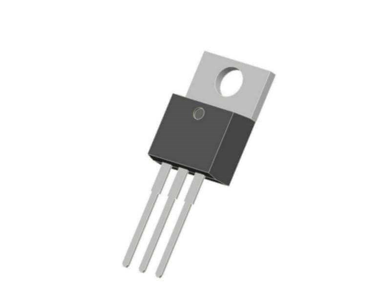
2SC2655 is a TO-92L or TO-92MOD packaging BJT transistor with many intriguing features in a tiny package that makes it perfect for use in a wide range of applications. It is an NPN transistor with a maximum collector current of 2A, allowing it to drive a wide range of electrical components that require 2A current.
However, the transistor can also be used as an audio amplifier, with a maximum audio output of 900mW and a maximum DC current gain of 70 to 240. However, some manufacturers provide these transistors in two different gain categories, which may be determined by glancing at the alphabet on the transistor below the component number. If the alphabet is "O," the gain is 70-120, and if the alphabet is "Y," the gain is 120-140.
Moreover, the transition frequency of the transistor is 100MHz due to which it can also be used in RF circuits under 100MHz.
C2655 Feature
• Low saturation voltage: VCE (sat) = 0.5 V (max) (IC = 1 A)
• High collector power dissipation: PC = 900 mW
• High-speed switching: tstg = 1.0 μs (typ.)
C2655 Application
Switching loads under 2000mA
Motor Controllers
Audio Amplifiers
Audio Amplifier Stages
AM & FM Radio & Transmitters
C2655 Equivalent
The equivalent for C2655:
2SC3328, STX715, KTC3209, MJE182 (TO-126 Package), 2SA1162 (TO-126 Package).
C2655 PNP Complementary
PNP Complementary of 2SC2655 is 2SA1020.
C2655 Uses
C2655 can be utilized in a wide range of general-purpose switching and amplification applications. When used as a switch, it may drive a variety of loads in 2A circuits. Loads can include high-power LEDs, relays, integrated circuits (ICs), and a variety of other electronic components.
It can offer 900mW of maximum audio amplification when used as an audio amplifier, allowing it to be utilized in audio amplifier stages or to drive a small 1-watt loudspeaker directly from a small audio input. It can be utilized as an amplifier in a variety of bell/chimes, mp3 player audio amplification, and a variety of other electrical applications that require audio amplification of 900mW. It can also be used for AM and FM broadcasting and receiving.
C2655 Safe Operating Guide
Always utilize the C2655 transistor at least 20% below its maximum ratings for long-term performance. Because the transistor's maximum collector current is 2A, do not drive a load greater than 1.6A for safety. The maximum collector-emitter voltage is 50V; for safety, no-load greater than 40V should be driven. The operation and storage temperatures of the transistor should be between -55 and +150 ℃.
C2655 Package

C2655 Package
C2655 Manufacturer
Toshiba Semiconductor & Storage offers a broad range of enabling technology solutions that allow OEMs, ODMs, CMs and fabless chip companies to develop advanced integrated products for the computing, networking, communications, digital consumer, automotive and other markets.
Specifications
- TypeParameter
What does the 2SC2655 transistor require?
2A current.
What is the maximum audio output of the 2SC2655 transistor?
900mW.
What is the gain of the 2SC2655 transistor if the alphabet is "O"?
120-140.
What is the transition frequency of the C2655?
100MHz.
What is 2SC2655?
A TO-92L or TO-92MOD packaging BJT transistor.
 BCM857BS Transistor: SOT363 Package, BCM857BS Datasheet, Pinout
21 February 20223107
 OV7670 vs OV2640 Which one is better?
03 March 20224572
 TPS2121RUXR Power Multiplexers: 12-VFQFN, Pinout, Datasheet
07 March 20224485
 TMC2100 VS DRV8825 VS A4988
27 April 20226480
 OPA1652 Audio Operational Amplifier: Datasheet, Pinout and Replacement
23 September 20212895
 IRF830 Power MOSFET: Pinout, Datasheet, and Test Circuit
14 July 20215031
 IRF5210 Power MOSFET: Datasheet, Price, Pinout
18 March 20224316
 DS1990A iButton: Where & How to use
03 November 20213613
 The Different Types of Circuit Breakers and Their Applications
11 April 20236238
 Introduction to Acceleration Sensors
07 November 20257769
 What is a Knock Sensor?
08 January 202618160
 What is a Delay Circuit? 6 Types of Delay Circuits Explained
28 March 202548875
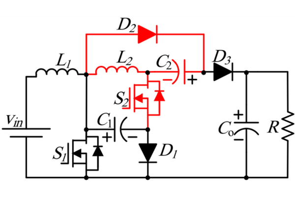 Optimizing Energy Management with Non-Isolated DC-DC Converters
04 February 20242971
 How Fast is Wi-Fi 6?
07 June 20215054
 Semiconductor Industry Techniques Revolutionize Battery Manufacturing
06 November 2023594
 An Overview of JFET
19 August 20208482
In Stock
United States
China
Canada
Japan
Russia
Germany
United Kingdom
Singapore
Italy
Hong Kong(China)
Taiwan(China)
France
Korea
Mexico
Netherlands
Malaysia
Austria
Spain
Switzerland
Poland
Thailand
Vietnam
India
United Arab Emirates
Afghanistan
Åland Islands
Albania
Algeria
American Samoa
Andorra
Angola
Anguilla
Antigua & Barbuda
Argentina
Armenia
Aruba
Australia
Azerbaijan
Bahamas
Bahrain
Bangladesh
Barbados
Belarus
Belgium
Belize
Benin
Bermuda
Bhutan
Bolivia
Bonaire, Sint Eustatius and Saba
Bosnia & Herzegovina
Botswana
Brazil
British Indian Ocean Territory
British Virgin Islands
Brunei
Bulgaria
Burkina Faso
Burundi
Cabo Verde
Cambodia
Cameroon
Cayman Islands
Central African Republic
Chad
Chile
Christmas Island
Cocos (Keeling) Islands
Colombia
Comoros
Congo
Congo (DRC)
Cook Islands
Costa Rica
Côte d’Ivoire
Croatia
Cuba
Curaçao
Cyprus
Czechia
Denmark
Djibouti
Dominica
Dominican Republic
Ecuador
Egypt
El Salvador
Equatorial Guinea
Eritrea
Estonia
Eswatini
Ethiopia
Falkland Islands
Faroe Islands
Fiji
Finland
French Guiana
French Polynesia
Gabon
Gambia
Georgia
Ghana
Gibraltar
Greece
Greenland
Grenada
Guadeloupe
Guam
Guatemala
Guernsey
Guinea
Guinea-Bissau
Guyana
Haiti
Honduras
Hungary
Iceland
Indonesia
Iran
Iraq
Ireland
Isle of Man
Israel
Jamaica
Jersey
Jordan
Kazakhstan
Kenya
Kiribati
Kosovo
Kuwait
Kyrgyzstan
Laos
Latvia
Lebanon
Lesotho
Liberia
Libya
Liechtenstein
Lithuania
Luxembourg
Macao(China)
Madagascar
Malawi
Maldives
Mali
Malta
Marshall Islands
Martinique
Mauritania
Mauritius
Mayotte
Micronesia
Moldova
Monaco
Mongolia
Montenegro
Montserrat
Morocco
Mozambique
Myanmar
Namibia
Nauru
Nepal
New Caledonia
New Zealand
Nicaragua
Niger
Nigeria
Niue
Norfolk Island
North Korea
North Macedonia
Northern Mariana Islands
Norway
Oman
Pakistan
Palau
Palestinian Authority
Panama
Papua New Guinea
Paraguay
Peru
Philippines
Pitcairn Islands
Portugal
Puerto Rico
Qatar
Réunion
Romania
Rwanda
Samoa
San Marino
São Tomé & Príncipe
Saudi Arabia
Senegal
Serbia
Seychelles
Sierra Leone
Sint Maarten
Slovakia
Slovenia
Solomon Islands
Somalia
South Africa
South Sudan
Sri Lanka
St Helena, Ascension, Tristan da Cunha
St. Barthélemy
St. Kitts & Nevis
St. Lucia
St. Martin
St. Pierre & Miquelon
St. Vincent & Grenadines
Sudan
Suriname
Svalbard & Jan Mayen
Sweden
Syria
Tajikistan
Tanzania
Timor-Leste
Togo
Tokelau
Tonga
Trinidad & Tobago
Tunisia
Turkey
Turkmenistan
Turks & Caicos Islands
Tuvalu
U.S. Outlying Islands
U.S. Virgin Islands
Uganda
Ukraine
Uruguay
Uzbekistan
Vanuatu
Vatican City
Venezuela
Wallis & Futuna
Yemen
Zambia
Zimbabwe