
 Product
 Brand
Brand Articles
 Tools
Tools
CA3240 IC OPAMP GP 2 CIRCUIT 8DIP[Video&FAQ]: Pinout, Equivalents, and Datasheet
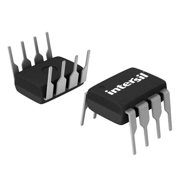
Intersil (Renesas Electronics America)
40mA per Channel 10pA 70 dB Instrumentational OP Amps 0.00064μA 8 Pins DIP
Unit Price: $2.944726
Ext Price: $2.94


40mA per Channel 10pA 70 dB Instrumentational OP Amps 0.00064μA 8 Pins DIP
The CA3240A and CA3240 are two different models of the popular CA3140 series of integrated circuit operational amplifiers. On a single monolithic device, they combine the advantages of MOS and bipolar transistors. This article is going to talk about the pinout, features, and application of CA3240.

Versus 10 IC Op-Amp | JRC4558 JRC4556 JRC4580 CA3240 NE5532 LM833 LF353 OPA2134 AD823 LM4562
- Overview of CA3240
- CA3240 Features
- CA3240 Pinout
- Specifications
- CA3240 Block Diagram
- CA3240 Schematic Diagram
- CA3240 Output Circuit Considerations
- CA3240 On/Off Touch Switch
- CA3240 Precision Differential Amplifier
- CA3240 Applications
- CA3240 Equivalents
- Where to Use CA3240 Op Amp
- CA3240 Manufacturer
- Datasheet PDF
- Popularity by Region
Overview of CA3240
The CA3240A and CA3240 are two different models of the popular CA3140 series of integrated circuit operational amplifiers. On a single monolithic device, they combine the advantages of MOS and bipolar transistors. High input impedance and a wide common-mode input voltage range are provided by gate-protected MOSFET (PMOS) input transistors (typically to 0.5V below the negative supply rail). The bipolar output transistors have a large output voltage swing and can handle a lot of currents.
CA3240 Features
• Dual Version of CA3140
• Internally Compensated
• MOSFET Input Stage
- Very High Input Impedance (ZIN) 1.5TΩ (Typ)
- Very Low Input Current (II) 10pA (Typ) at ±15V
- Wide Common-Mode Input Voltage Range (VICR): Can Be Swung 0.5V Below Negative Supply Voltage Rail
• Directly Replaces Industry Type 741 in Most Applications
• Pb-Free Available (RoHS Compliant)
CA3240 Pinout

CA3240 Pinout
Pin Descriptions
| Pin Number | Pin Name | Description |
| 1 | OUT (A) | The output pin of the Op-amp A |
| 2 | Inverting Input (A) | The Inverting input pin of the Op-Amp A |
| 3 | Non-Inverting Input (A) | The Non-Inverting Input Pin of Amplifier A |
| 4 | Power (-Vs) | Negative supply terminal |
| 5 | Reference | The Non-Inverting Input Pin of Amplifier B |
| 6 | Output | The Inverting input pin of the Op-Amp B |
| 7 | Power (+Vs) | The output pin of the Op-amp B |
| 8 | +V S | Positive supply terminal |
Specifications
- TypeParameter
- Contact Plating
Contact plating (finish) provides corrosion protection for base metals and optimizes the mechanical and electrical properties of the contact interfaces.
Lead, Tin - Mount
In electronic components, the term "Mount" typically refers to the method or process of physically attaching or fixing a component onto a circuit board or other electronic device. This can involve soldering, adhesive bonding, or other techniques to secure the component in place. The mounting process is crucial for ensuring proper electrical connections and mechanical stability within the electronic system. Different components may have specific mounting requirements based on their size, shape, and function, and manufacturers provide guidelines for proper mounting procedures to ensure optimal performance and reliability of the electronic device.
Surface Mount, Through Hole - Package / Case
refers to the protective housing that encases an electronic component, providing mechanical support, electrical connections, and thermal management.
DIP - Number of Pins8
- Published1998
- JESD-609 Code
The "JESD-609 Code" in electronic components refers to a standardized marking code that indicates the lead-free solder composition and finish of electronic components for compliance with environmental regulations.
e0 - Pbfree Code
The "Pbfree Code" parameter in electronic components refers to the code or marking used to indicate that the component is lead-free. Lead (Pb) is a toxic substance that has been widely used in electronic components for many years, but due to environmental concerns, there has been a shift towards lead-free alternatives. The Pbfree Code helps manufacturers and users easily identify components that do not contain lead, ensuring compliance with regulations and promoting environmentally friendly practices. It is important to pay attention to the Pbfree Code when selecting electronic components to ensure they meet the necessary requirements for lead-free applications.
no - Part Status
Parts can have many statuses as they progress through the configuration, analysis, review, and approval stages.
Discontinued - Number of Terminations8
- ECCN Code
An ECCN (Export Control Classification Number) is an alphanumeric code used by the U.S. Bureau of Industry and Security to identify and categorize electronic components and other dual-use items that may require an export license based on their technical characteristics and potential for military use.
EAR99 - Terminal Finish
Terminal Finish refers to the surface treatment applied to the terminals or leads of electronic components to enhance their performance and longevity. It can improve solderability, corrosion resistance, and overall reliability of the connection in electronic assemblies. Common finishes include nickel, gold, and tin, each possessing distinct properties suitable for various applications. The choice of terminal finish can significantly impact the durability and effectiveness of electronic devices.
Tin/Lead (Sn/Pb) - Max Operating Temperature
The Maximum Operating Temperature is the maximum body temperature at which the thermistor is designed to operate for extended periods of time with acceptable stability of its electrical characteristics.
85°C - Min Operating Temperature
The "Min Operating Temperature" parameter in electronic components refers to the lowest temperature at which the component is designed to operate effectively and reliably. This parameter is crucial for ensuring the proper functioning and longevity of the component, as operating below this temperature may lead to performance issues or even damage. Manufacturers specify the minimum operating temperature to provide guidance to users on the environmental conditions in which the component can safely operate. It is important to adhere to this parameter to prevent malfunctions and ensure the overall reliability of the electronic system.
-40°C - Terminal Position
In electronic components, the term "Terminal Position" refers to the physical location of the connection points on the component where external electrical connections can be made. These connection points, known as terminals, are typically used to attach wires, leads, or other components to the main body of the electronic component. The terminal position is important for ensuring proper connectivity and functionality of the component within a circuit. It is often specified in technical datasheets or component specifications to help designers and engineers understand how to properly integrate the component into their circuit designs.
DUAL - Peak Reflow Temperature (Cel)
Peak Reflow Temperature (Cel) is a parameter that specifies the maximum temperature at which an electronic component can be exposed during the reflow soldering process. Reflow soldering is a common method used to attach electronic components to a circuit board. The Peak Reflow Temperature is crucial because it ensures that the component is not damaged or degraded during the soldering process. Exceeding the specified Peak Reflow Temperature can lead to issues such as component failure, reduced performance, or even permanent damage to the component. It is important for manufacturers and assemblers to adhere to the recommended Peak Reflow Temperature to ensure the reliability and functionality of the electronic components.
NOT SPECIFIED - Number of Functions2
- Supply Voltage
Supply voltage refers to the electrical potential difference provided to an electronic component or circuit. It is crucial for the proper operation of devices, as it powers their functions and determines performance characteristics. The supply voltage must be within specified limits to ensure reliability and prevent damage to components. Different electronic devices have specific supply voltage requirements, which can vary widely depending on their design and intended application.
15V - Time@Peak Reflow Temperature-Max (s)
Time@Peak Reflow Temperature-Max (s) refers to the maximum duration that an electronic component can be exposed to the peak reflow temperature during the soldering process, which is crucial for ensuring reliable solder joint formation without damaging the component.
NOT SPECIFIED - Pin Count
a count of all of the component leads (or pins)
8 - Qualification Status
An indicator of formal certification of qualifications.
Not Qualified - Power Supplies
an electronic circuit that converts the voltage of an alternating current (AC) into a direct current (DC) voltage.?
5/+-15V - Temperature Grade
Temperature grades represent a tire's resistance to heat and its ability to dissipate heat when tested under controlled laboratory test conditions.
INDUSTRIAL - Number of Circuits2
- Max Supply Voltage
In general, the absolute maximum common-mode voltage is VEE-0.3V and VCC+0.3V, but for products without a protection element at the VCC side, voltages up to the absolute maximum rated supply voltage (i.e. VEE+36V) can be supplied, regardless of supply voltage.
36V - Min Supply Voltage
The minimum supply voltage (V min ) is explored for sequential logic circuits by statistically simulating the impact of within-die process variations and gate-dielectric soft breakdown on data retention and hold time.
4V - Operating Supply Current
Operating Supply Current, also known as supply current or quiescent current, is a crucial parameter in electronic components that indicates the amount of current required for the device to operate under normal conditions. It represents the current drawn by the component from the power supply while it is functioning. This parameter is important for determining the power consumption of the component and is typically specified in datasheets to help designers calculate the overall power requirements of their circuits. Understanding the operating supply current is essential for ensuring proper functionality and efficiency of electronic systems.
8mA - Slew Rate
the maximum rate of output voltage change per unit time.
9 V/μs - Architecture
In electronic components, the parameter "Architecture" refers to the overall design and structure of the component. It encompasses the arrangement of internal components, the layout of circuitry, and the physical form of the component. The architecture of an electronic component plays a crucial role in determining its functionality, performance, and compatibility with other components in a system. Different architectures can result in variations in power consumption, speed, size, and other key characteristics of the component. Designers often consider the architecture of electronic components carefully to ensure optimal performance and integration within a larger system.
VOLTAGE-FEEDBACK - Amplifier Type
Amplifier Type refers to the classification or categorization of amplifiers based on their design, functionality, and characteristics. Amplifiers are electronic devices that increase the amplitude of a signal, such as voltage or current. The type of amplifier determines its specific application, performance capabilities, and operating characteristics. Common types of amplifiers include operational amplifiers (op-amps), power amplifiers, audio amplifiers, and radio frequency (RF) amplifiers. Understanding the amplifier type is crucial for selecting the right component for a particular circuit or system design.
OPERATIONAL AMPLIFIER - Common Mode Rejection Ratio
Common Mode Rejection Ratio (CMRR) is a measure of the ability of a differential amplifier to reject input signals that are common to both input terminals. It is defined as the ratio of the differential gain to the common mode gain. A high CMRR indicates that the amplifier can effectively eliminate noise and interference that affects both inputs simultaneously, enhancing the fidelity of the amplified signal. CMRR is typically expressed in decibels (dB), with higher values representing better performance in rejecting common mode signals.
70 dB - Current - Input Bias
The parameter "Current - Input Bias" in electronic components refers to the amount of current required at the input terminal of a device to maintain proper operation. It is a crucial specification as it determines the minimum input current needed for the component to function correctly. Input bias current can affect the performance and accuracy of the device, especially in precision applications where small signal levels are involved. It is typically specified in datasheets for operational amplifiers, transistors, and other semiconductor devices to provide users with important information for circuit design and analysis.
10pA - Output Current per Channel
Output Current per Channel is a specification commonly found in electronic components such as amplifiers, audio interfaces, and power supplies. It refers to the maximum amount of electrical current that can be delivered by each individual output channel of the component. This parameter is important because it determines the capacity of the component to drive connected devices or loads. A higher output current per channel means the component can deliver more power to connected devices, while a lower output current may limit the performance or functionality of the component in certain applications. It is crucial to consider the output current per channel when selecting electronic components to ensure they can meet the power requirements of the intended system or setup.
40mA - Input Offset Voltage (Vos)
Input Offset Voltage (Vos) is a key parameter in electronic components, particularly in operational amplifiers. It refers to the voltage difference that must be applied between the two input terminals of the amplifier to nullify the output voltage when the input terminals are shorted together. In simpler terms, it represents the voltage required to bring the output of the amplifier to zero when there is no input signal present. Vos is an important parameter as it can introduce errors in the output signal of the amplifier, especially in precision applications where accuracy is crucial. Minimizing Vos is essential to ensure the amplifier operates with high precision and accuracy.
5mV - Gain Bandwidth Product
The gain–bandwidth product (designated as GBWP, GBW, GBP, or GB) for an amplifier is the product of the amplifier's bandwidth and the gain at which the bandwidth is measured.
4.5MHz - Neg Supply Voltage-Nom (Vsup)
The parameter "Neg Supply Voltage-Nom (Vsup)" in electronic components refers to the nominal negative supply voltage that the component requires to operate within its specified performance characteristics. This parameter indicates the minimum voltage level that must be provided to the component's negative supply pin for proper functionality. It is important to ensure that the negative supply voltage provided to the component does not exceed the maximum specified value to prevent damage or malfunction. Understanding and adhering to the specified negative supply voltage requirements is crucial for the reliable operation of the electronic component in a circuit.
-15V - Unity Gain BW-Nom
Unity Gain Bandwidth, often abbreviated as Unity Gain BW or UGBW, refers to the frequency at which an amplifier can provide a gain of one (0 dB). It is a critical parameter in assessing the performance of operational amplifiers and other amplifying devices, indicating the range of frequencies over which the amplifier can operate without distortion. Unity Gain BW is particularly important in applications where signal fidelity is crucial, as it helps determine the maximum frequency of operation for a given gain level. As the gain is reduced, the bandwidth typically increases, ensuring that the amplifier can still operate effectively across various signal frequencies.
4500 kHz - Voltage Gain
Voltage gain is a measure of how much an electronic component or circuit amplifies an input voltage signal to produce an output voltage signal. It is typically expressed as a ratio or in decibels (dB). A higher voltage gain indicates a greater amplification of the input signal. Voltage gain is an important parameter in amplifiers, where it determines the level of amplification provided by the circuit. It is calculated by dividing the output voltage by the input voltage and is a key factor in determining the overall performance and functionality of electronic devices.
100dB - Average Bias Current-Max (IIB)
The parameter "Average Bias Current-Max (IIB)" in electronic components refers to the maximum average bias current that the component can handle without exceeding its specified operating limits. Bias current is the current that flows through a component when it is in its quiescent state or when it is not actively processing a signal. Exceeding the maximum average bias current can lead to overheating, reduced performance, or even damage to the component. Therefore, it is important to ensure that the bias current does not exceed the specified maximum value to maintain the reliability and longevity of the electronic component.
0.00064μA - Low-Offset
Low-offset is a parameter used to describe the level of offset voltage in electronic components, particularly in operational amplifiers. Offset voltage refers to the small voltage difference that exists between the input terminals of the amplifier when the input voltage is zero. A low-offset value indicates that this voltage difference is minimal, which is desirable for accurate signal processing and amplification. Components with low-offset specifications are preferred in applications where precision and accuracy are critical, such as in instrumentation and measurement systems. Minimizing offset voltage helps reduce errors and ensures the faithful reproduction of input signals by the amplifier.
NO - Frequency Compensation
Frequency compensation is implemented by modifying the gain and phase characteristics of the amplifier's open loop output or of its feedback network, or both, in such a way as to avoid the conditions leading to oscillation. This is usually done by the internal or external use of resistance-capacitance networks.
YES - Max Dual Supply Voltage
A Dual power supply is a regular direct current power supply. It can provide a positive as well as negative voltage. It ensures stable power supply to the device as well as it helps to prevent system damage.
18V - Low-Bias
Low-bias in electronic components refers to a design or configuration that minimizes the amount of bias current flowing through the component. Bias current is a small, steady current that is used to establish the operating point of a component, such as a transistor or amplifier. By reducing the bias current to a low level, the component can operate with lower power consumption and potentially lower distortion. Low-bias components are often used in applications where power efficiency and signal fidelity are important, such as in audio amplifiers or battery-powered devices. Overall, the low-bias parameter indicates the ability of the component to operate efficiently and accurately with minimal bias current.
YES - Min Dual Supply Voltage
The parameter "Min Dual Supply Voltage" in electronic components refers to the minimum voltage required for the proper operation of a device that uses dual power supplies. Dual power supplies typically consist of a positive and a negative voltage source. The "Min Dual Supply Voltage" specification ensures that both the positive and negative supply voltages are within a certain range to guarantee the device functions correctly. It is important to adhere to this parameter to prevent damage to the component and ensure reliable performance.
2V - Bias Current-Max (IIB) @25C
The parameter "Bias Current-Max (IIB) @25C" in electronic components refers to the maximum input bias current that the component can handle at a specified temperature of 25 degrees Celsius. Bias current is the current flowing into the input terminal of a device when no signal is applied. This parameter is important because excessive bias current can affect the performance and stability of the component, leading to potential issues such as distortion or offset errors in the output signal. By specifying the maximum bias current allowed at a certain temperature, manufacturers provide users with important information to ensure proper operation and reliability of the component in their circuit designs.
0.00005μA - Height4.57mm
- Length10.16mm
- Width7.11mm
- RoHS Status
RoHS means “Restriction of Certain Hazardous Substances” in the “Hazardous Substances Directive” in electrical and electronic equipment.
RoHS Compliant
CA3240 Block Diagram

CA3240 Block Diagram
CA3240 Schematic Diagram

CA3240 schematic Diagram
CA3240 Output Circuit Considerations
Figure 3 depicts some typical setups. In both circumstances, a series resistor (RL) is employed to limit the amount of drive accessible to the driven device. Furthermore, a series diode and a shunt diode should be employed at the thyristor input to protect the integrated circuit from strong negative transient surges that can develop at the gate of thyristors.

CA3240 Output Circuit Considerations
CA3240 On/Off Touch Switch
The CA3240E is used in the on/off touch switch depicted in Figure 5 to detect tiny currents flowing between two contact sites on a touch panel made of a PC board metallization "grid." When the "on" plate is pressed, current flows between the grid's two sides, generating a positive shift in the CA3240E's output voltage (Terminal 7). The CA3059 is utilized as a latching circuit and a zero-crossing TRIAC driver, and it receives these positive transitions.

CA3240 On and Off Touch Switch
CA3240 Precision Differential Amplifier
Figure 9 shows the CA3240E in the classical precision differential amplifier circuit. The CA3240E is ideally suited for biomedical applications because of its extremely high input impedance. To ensure patient safety, an extremely high electrode series resistance is required to limit any current
that might result in patient discomfort in the event of a fault condition. In this case, 10MΩ resistors have been used to limit the current to less than 2µA without affecting the performance of the circuit.

CA3240 Precision Differential Amplifier
CA3240 Applications
Ground Referenced Single Amplifiers in Automobile and Portable Instrumentation
Sample and Hold Amplifiers
Long Duration Timers/Multivibrators (MicrosecondsMinutes-Hours)
Photocurrent Instrumentation
Intrusion Alarm System
Comparators
Instrumentation Amplifiers
Active Filters
Function Generators
Power Supplies
Where to Use CA3240 Op Amp
The CA3240 IC can be used to implement general-purpose op-amp circuits such as comparator, differential amplification, and mathematical computations. Furthermore, the device is developed specifically for applications such as transducer amplifiers and dc amplification blocks, making it easier to install in single-supply-voltage systems. These devices, for example, can be powered directly from the normal 5V supply used in digital electronics without the need for a separate -5V supply.
Because the gadget has two of such op-amps on board, it may execute two separate functions at the same time, which is useful in applications. Because of its inexpensive cost and high performance, the device is popular among hobbyists and engineers.
CA3240 Manufacturer
Renesas Electronics Corporation, headquartered in Tokyo, Japan, was founded in 2002 as Renesas Technology, a consolidated entity of Hitachi and Mitsubishi semiconductor units excluding their dynamic random-access memory businesses, with which NEC Electronics merged in 2010, resulting in a minor change in the corporate name and logo to what it is now.
Datasheet PDF
- Datasheets :
Popularity by Region
How many pins of CA3240?
8 pins.
What’s the operating temperature of CA3240?
-40°C to 85°C.
What is operational amplifier?
A weak electric signal can be amplified using an operational amplifier, which is an integrated circuit. Two input pins and one output pin make up an operational amplifier. The voltage difference between the two input pins is amplified and output.
Why is it called operational amplifier?
Op-amps got their name because they were originally employed in electrical analog computers to mimic basic mathematical operations like addition, subtraction, integration, differentiation, and so on. A real operational amplifier is an ideal circuit element in this regard.
 The Review of W5500 Hardwired TCP IP Embedded Ethernet Controller
14 April 202210185
 Unveiling the PIC16CE62X OTP 8-bit CMOS MCU with EEPROM Data Memory: Technical Deep Dive
29 February 2024457
 Advantech Corp 96MPXE-2.1-16M36: A Discontinued Skylake Microprocessor Module
11 March 20243632
 STM8L101 Microcontroller Series: A Comprehensive Technical Analysis
29 February 2024179
 74LS74 Dual D Flip-Flop: How to Use it?
12 November 202119421
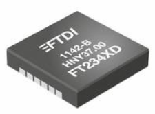 FT234XD-R USB: Pinout, Block Diagram, Alternatives
20 February 20232529
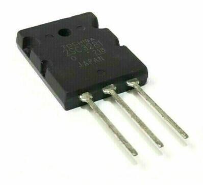 2SC3281 NPN Power Transistor: 200V Power Transistor, Datasheet pdf and Equivalent
22 December 20217687
 TPS51219RTER Controller: Datasheet, Price, Application Circuit
23 March 20221394
 Graphics Card Explained: Classification, Working and Structure
27 May 202113993
 A Guide to Semiconductor IP Core
18 January 202210292
 Best Practices for Panel Meter Maintenance
11 July 20251392
 Electronic Components Distributor Utmel to Showcase at 2024 IPC APEX EXPO
10 April 20245879
 A Combo for Innovation: Open Source and Crowdfunding
15 November 20195407
 Semiconductor Industry Techniques Revolutionize Battery Manufacturing
06 November 20232388
 0 Ohm Resistor Explained
10 December 202119795
 Latches, Flip-Flops, Registers and Buffers
15 February 202218440
Intersil (Renesas Electronics America)
In Stock: 408
Minimum: 1 Multiples: 1
Qty
Unit Price
Ext Price
1
$2.944726
$2.94
10
$2.778044
$27.78
100
$2.620796
$262.08
500
$2.472449
$1,236.22
1000
$2.332499
$2,332.50
Not the price you want? Send RFQ Now and we'll contact you ASAP.
Inquire for More Quantity
![ISL55001IBZ-T7]() ISL55001IBZ-T7
ISL55001IBZ-T7Intersil (Renesas Electronics America)
![ISL28210FBZ]() ISL28210FBZ
ISL28210FBZIntersil (Renesas Electronics America)
![EL5175IS]() EL5175IS
EL5175ISIntersil (Renesas Electronics America)
![ISL28213FUZ-T7]() ISL28213FUZ-T7
ISL28213FUZ-T7Intersil (Renesas Electronics America)
![CA3130EZ]() CA3130EZ
CA3130EZIntersil (Renesas Electronics America)
![CA3140E]() CA3140E
CA3140EIntersil (Renesas Electronics America)
![ISL28158FBZ]() ISL28158FBZ
ISL28158FBZIntersil (Renesas Electronics America)
![CA3140EZ]() CA3140EZ
CA3140EZIntersil (Renesas Electronics America)
![ISL55002IBZ-T7]() ISL55002IBZ-T7
ISL55002IBZ-T7Intersil (Renesas Electronics America)
![CA3140AEZ]() CA3140AEZ
CA3140AEZIntersil (Renesas Electronics America)


