

 Product
 Brand
Brand Articles
 Tools
Tools
CD40106BC Hex Schmitt Trigger: Pinout, Features and Datasheet


160 ns ns 400 ns ns Gates & Inverters Surface Mount Surface Mount 3V~15V V 4μA μA
The CD40106BC Hex Schmitt Trigger is a monolithic complementary MOS (CMOS) integrated circuit constructed with N and P-channel enhancement transistors. Furthermore, Huge range of Semiconductors, Capacitors, Resistors and IcS in stock. Welcome RFQ.

What Is Schmitt Trigger and How It Works
CD40106BC Pinout
The following figure is the diagram of CD40106BC Pinout.
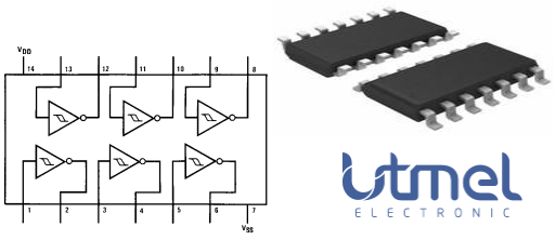
Pinout
CD40106BC CAD Model
The followings are CD40106BC Symbol, Footprint, and 3D Model.
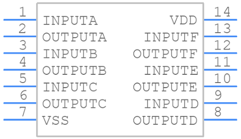
PCB Symbol
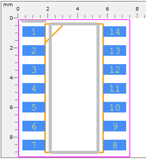
PCB Footprint
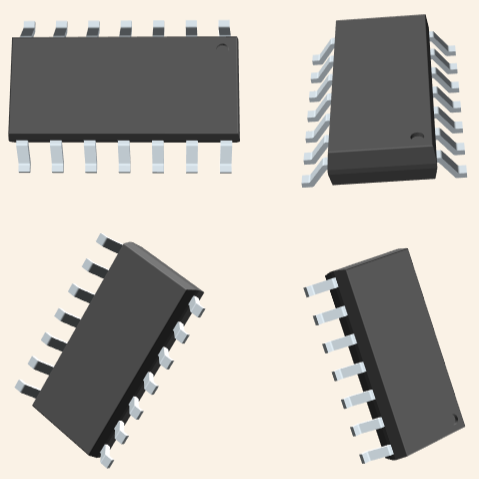
3D Model
CD40106BC Overview
The CD40106BC Hex Schmitt Trigger is a monolithic complementary MOS (CMOS) integrated circuit constructed with N and P-channel enhancement transistors. The positive and negative-going threshold voltages, VT+ and VT−, show low variation with respect to temperature (typ 0.0005V/°C at VDD = 10V), and hysteresis, VT+ − VT− ≥ 0.2 VDD is guaranteed. All inputs are protected from damage due to static discharge by diode clamps to VDD and VSS.
This article provides you with a basic overview of the CD40106BC Hex Schmitt Trigger, including its pin descriptions, features and specifications, etc., to help you quickly understand what CD40106BC is.
CD40106BC Features
● Wide supply voltage range: 3V to 15V
● High noise immunity: 0.7 VDD (typ.)
● Low power TTL compatibility: Fan out of 2 driving 74L or 1 driving 74LS
● Hysteresis: 0.4 VDD (typ.), 0.2 VDD guaranteed
● Equivalent to MM74C14
Specifications
- TypeParameter
- Package / Case
refers to the protective housing that encases an electronic component, providing mechanical support, electrical connections, and thermal management.
14-SOIC (0.154, 3.90mm Width) - Mounting Type
The "Mounting Type" in electronic components refers to the method used to attach or connect a component to a circuit board or other substrate, such as through-hole, surface-mount, or panel mount.
Surface Mount - Mount
In electronic components, the term "Mount" typically refers to the method or process of physically attaching or fixing a component onto a circuit board or other electronic device. This can involve soldering, adhesive bonding, or other techniques to secure the component in place. The mounting process is crucial for ensuring proper electrical connections and mechanical stability within the electronic system. Different components may have specific mounting requirements based on their size, shape, and function, and manufacturers provide guidelines for proper mounting procedures to ensure optimal performance and reliability of the electronic device.
Surface Mount - Number of Pins14
- Supplier Device Package
The parameter "Supplier Device Package" in electronic components refers to the physical packaging or housing of the component as provided by the supplier. It specifies the form factor, dimensions, and layout of the component, which are crucial for compatibility and integration into electronic circuits and systems. The supplier device package information typically includes details such as the package type (e.g., DIP, SOP, QFN), number of pins, pitch, and overall size, allowing engineers and designers to select the appropriate component for their specific application requirements. Understanding the supplier device package is essential for proper component selection, placement, and soldering during the manufacturing process to ensure optimal performance and reliability of the electronic system.
14-SOIC - Number of Elements6
- Logic Level-Low0.7V ~ 2.1V
- Logic Level-High4.3V ~ 12.9V
- Published2003
- Series
In electronic components, the "Series" refers to a group of products that share similar characteristics, designs, or functionalities, often produced by the same manufacturer. These components within a series typically have common specifications but may vary in terms of voltage, power, or packaging to meet different application needs. The series name helps identify and differentiate between various product lines within a manufacturer's catalog.
4000B - Packaging
Semiconductor package is a carrier / shell used to contain and cover one or more semiconductor components or integrated circuits. The material of the shell can be metal, plastic, glass or ceramic.
Tube - Operating Temperature
The operating temperature is the range of ambient temperature within which a power supply, or any other electrical equipment, operate in. This ranges from a minimum operating temperature, to a peak or maximum operating temperature, outside which, the power supply may fail.
-55°C~125°C - Part Status
Parts can have many statuses as they progress through the configuration, analysis, review, and approval stages.
Obsolete - Moisture Sensitivity Level (MSL)
Moisture Sensitivity Level (MSL) is a standardized rating that indicates the susceptibility of electronic components, particularly semiconductors, to moisture-induced damage during storage and the soldering process, defining the allowable exposure time to ambient conditions before they require special handling or baking to prevent failures
1 (Unlimited) - Termination
Termination in electronic components refers to the practice of matching the impedance of a circuit to prevent signal reflections and ensure maximum power transfer. It involves the use of resistors or other components at the end of transmission lines or connections. Proper termination is crucial in high-frequency applications to maintain signal integrity and reduce noise.
SMD/SMT - Max Operating Temperature
The Maximum Operating Temperature is the maximum body temperature at which the thermistor is designed to operate for extended periods of time with acceptable stability of its electrical characteristics.
125°C - Min Operating Temperature
The "Min Operating Temperature" parameter in electronic components refers to the lowest temperature at which the component is designed to operate effectively and reliably. This parameter is crucial for ensuring the proper functioning and longevity of the component, as operating below this temperature may lead to performance issues or even damage. Manufacturers specify the minimum operating temperature to provide guidance to users on the environmental conditions in which the component can safely operate. It is important to adhere to this parameter to prevent malfunctions and ensure the overall reliability of the electronic system.
-55°C - Voltage - Supply
Voltage - Supply refers to the range of voltage levels that an electronic component or circuit is designed to operate with. It indicates the minimum and maximum supply voltage that can be applied for the device to function properly. Providing supply voltages outside this range can lead to malfunction, damage, or reduced performance. This parameter is critical for ensuring compatibility between different components in a circuit.
3V~15V - Base Part Number
The "Base Part Number" (BPN) in electronic components serves a similar purpose to the "Base Product Number." It refers to the primary identifier for a component that captures the essential characteristics shared by a group of similar components. The BPN provides a fundamental way to reference a family or series of components without specifying all the variations and specific details.
40106 - Max Output Current
The maximum current that can be supplied to the load.
8.8mA - Voltage
Voltage is a measure of the electric potential difference between two points in an electrical circuit. It is typically represented by the symbol "V" and is measured in volts. Voltage is a crucial parameter in electronic components as it determines the flow of electric current through a circuit. It is responsible for driving the movement of electrons from one point to another, providing the energy needed for electronic devices to function properly. In summary, voltage is a fundamental concept in electronics that plays a key role in the operation and performance of electronic components.
15V - Number of Circuits6
- Max Supply Voltage
In general, the absolute maximum common-mode voltage is VEE-0.3V and VCC+0.3V, but for products without a protection element at the VCC side, voltages up to the absolute maximum rated supply voltage (i.e. VEE+36V) can be supplied, regardless of supply voltage.
15V - Min Supply Voltage
The minimum supply voltage (V min ) is explored for sequential logic circuits by statistically simulating the impact of within-die process variations and gate-dielectric soft breakdown on data retention and hold time.
3V - Current - Output
Current - Output is a parameter in electronic components that refers to the maximum amount of current that can be delivered by the output of the component. It is a crucial specification as it determines the capability of the component to supply power to connected devices or circuits. The current output rating is typically specified in amperes (A) and is important for ensuring that the component can safely and effectively power the load it is connected to without overheating or failing. Designers and engineers must consider the current output rating when selecting components to ensure compatibility and reliable operation of the overall system.
8.8mA - Propagation Delay
the flight time of packets over the transmission link and is limited by the speed of light.
160 ns - Quiescent Current
The quiescent current is defined as the current level in the amplifier when it is producing an output of zero.
4μA - Turn On Delay Time
Turn-on delay, td(on), is the time taken to charge the input capacitance of the device before drain current conduction can start.
400 ns - Logic Function
In electronic components, the term "Logic Function" refers to the specific operation or behavior of a component based on its input signals. It describes how the component processes the input signals to produce the desired output. Logic functions are fundamental to digital circuits and are used to perform logical operations such as AND, OR, NOT, and XOR.Each electronic component, such as logic gates or flip-flops, is designed to perform a specific logic function based on its internal circuitry. By understanding the logic function of a component, engineers can design and analyze complex digital systems to ensure proper functionality and performance. Different logic functions can be combined to create more complex operations, allowing for the creation of sophisticated digital devices and systems.
Buffer, Inverter, Schmitt Trigger - Number of Inputs6
- Logic Type
Logic Type in electronic components refers to the classification of circuits based on the logical operations they perform. It includes types such as AND, OR, NOT, NAND, NOR, XOR, and XNOR, each defining the relationship between binary inputs and outputs. The logic type determines how the inputs affect the output state based on specific rules of Boolean algebra. This classification is crucial for designing digital circuits and systems, enabling engineers to select appropriate components for desired functionalities.
Inverter - Number of Gates
The number of gates per IC varies depending on the number of inputs per gate. Two?input gates are common, but if only a single input is required, such as in the 744 NOT(or inverter) gates, a 14 pin IC can accommodate 6 (or Hex) gates.
6 - Max Propagation Delay @ V, Max CL
The parameter "Max Propagation Delay @ V, Max CL" in electronic components refers to the maximum amount of time it takes for a signal to propagate through the component from input to output when operating at a specific voltage (V) and driving a maximum specified load capacitance (CL). This parameter is crucial in determining the speed and performance of the component in a circuit. A shorter propagation delay indicates faster signal processing and better overall performance. Designers use this parameter to ensure that signals can be transmitted and received within the required timing constraints in their electronic systems.
160ns @ 15V, 50pF - High Level Output Current
High-level Output Current IOH The current flowing into the output at a specified high- level voltage. Low-level Output Current IOL The current flowing into the output at a specified low- level output voltage.
-4.2mA - Low Level Output Current
The current into the output terminal with input conditions applied that, according to the product specification, will establish a low level at the output.
4.2mA - Current - Quiescent (Max)
The parameter "Current - Quiescent (Max)" in electronic components refers to the maximum amount of current that a device consumes when it is in a quiescent or idle state. This parameter is important because it indicates the minimum power consumption of the device when it is not actively performing any tasks. It is typically measured in units of amperes (A) and helps in determining the overall power efficiency and battery life of the electronic component. Designers and engineers use this parameter to ensure that the device meets power consumption requirements and operates within specified limits during standby or idle modes.
4μA - Features
In the context of electronic components, the term "Features" typically refers to the specific characteristics or functionalities that a particular component offers. These features can vary depending on the type of component and its intended use. For example, a microcontroller may have features such as built-in memory, analog-to-digital converters, and communication interfaces like UART or SPI.When evaluating electronic components, understanding their features is crucial in determining whether they meet the requirements of a particular project or application. Engineers and designers often look at features such as operating voltage, speed, power consumption, and communication protocols to ensure compatibility and optimal performance.In summary, the "Features" parameter in electronic components describes the unique attributes and capabilities that differentiate one component from another, helping users make informed decisions when selecting components for their electronic designs.
Schmitt Trigger - RoHS Status
RoHS means “Restriction of Certain Hazardous Substances” in the “Hazardous Substances Directive” in electrical and electronic equipment.
RoHS Compliant - REACH SVHC
The parameter "REACH SVHC" in electronic components refers to the compliance with the Registration, Evaluation, Authorization, and Restriction of Chemicals (REACH) regulation regarding Substances of Very High Concern (SVHC). SVHCs are substances that may have serious effects on human health or the environment, and their use is regulated under REACH to ensure their safe handling and minimize their impact.Manufacturers of electronic components need to declare if their products contain any SVHCs above a certain threshold concentration and provide information on the safe use of these substances. This information allows customers to make informed decisions about the potential risks associated with using the components and take appropriate measures to mitigate any hazards.Ensuring compliance with REACH SVHC requirements is essential for electronics manufacturers to meet regulatory standards, protect human health and the environment, and maintain transparency in their supply chain. It also demonstrates a commitment to sustainability and responsible manufacturing practices in the electronics industry.
No SVHC - Lead Free
Lead Free is a term used to describe electronic components that do not contain lead as part of their composition. Lead is a toxic material that can have harmful effects on human health and the environment, so the electronics industry has been moving towards lead-free components to reduce these risks. Lead-free components are typically made using alternative materials such as silver, copper, and tin. Manufacturers must comply with regulations such as the Restriction of Hazardous Substances (RoHS) directive to ensure that their products are lead-free and environmentally friendly.
Lead Free
CD40106BC Functional Block Diagram
The following is the Schematic Diagram of CD40106BC.

Schematic Diagram
CD40106BC Package
The following diagrams show the CD40106BC Package.
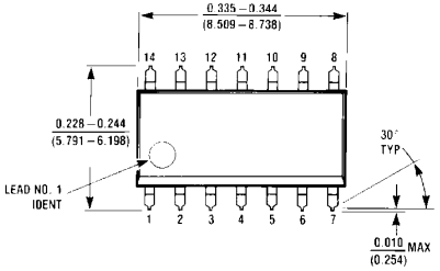
View A
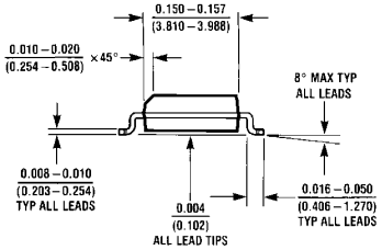
View B
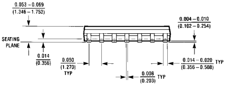
View C
CD40106BC Manufacturer
ON Semiconductor (Nasdaq: ON) is driving energy efficient innovations, empowering customers to reduce global energy use. The company offers a comprehensive portfolio of energy efficient power and signal management, logic, discrete and custom solutions to help design engineers solve their unique design challenges in automotive, communications, computing, consumer, industrial, LED lighting, medical, military/aerospace and power supply applications. ON Semiconductor operates a responsive, reliable, world-class supply chain and quality program, and a network of manufacturing facilities, sales offices and design centers in key markets throughout North America, Europe, and the Asia Pacific regions.
Datasheet PDF
- Datasheets :
- ReachStatement :
What is Hex Schmitt trigger?
An inverter Schmitt trigger is a device that converts any form of an input signal into a digital output signal, so it can function both with digital inputs as well as analog. ... In a Schmitt trigger, there is a wide.
What is Schmitt trigger used for?
Schmitt trigger devices are typically used in signal conditioning applications to remove noise from signals used in digital circuits, particularly mechanical contact bounce in switches.
Why is Schmitt trigger called regenerative comparator?
A Schmitt trigger circuit is also called a regenerative comparator circuit. The circuit is designed with a positive feedback and hence will have a regenerative action which will make the output switch levels. ... It is basically an inverting comparator circuit with a positive feedback.
What are the types of Schmitt trigger?
These are classified into two types namely inverting Schmitt trigger and non inverting Schmitt trigger. The inverting Schmitt trigger can be defined as an element of output is connected to the positive terminal of the operational amplifier.
 LR44 Battery: Equivalent, Specifications and Replacements
05 November 2021156406
 TPS40304DRCR Synchronous Buck Controller: Datasheet, Circuit, Pinout
23 March 2022750
![AD584 Precision Voltage Reference: Pinout, Features and Datasheet [FAQ]](https://res.utmel.com/Images/Article/0f6e8ef3-90eb-47b0-bdf7-30e675aaf8f5.png) AD584 Precision Voltage Reference: Pinout, Features and Datasheet [FAQ]
AD584 Precision Voltage Reference: Pinout, Features and Datasheet [FAQ]06 May 20222872
 IR2153 Half-Bridge Driver: Datasheet, Circuit and Equivalent
14 October 202116283
 TL082 JFET Dual Op-Amp: Where & How to Use TL082?
08 December 202113782
 LM340 Voltage Regulator: Datasheet, Pinout and Circuit
28 September 20217572
 TDA1517P Power Amplifier: Circuit, Replacement and Pinout
20 August 202121617
 Microchip PIC32MX Series: Technical Overview
29 February 2024372
 Coping with Radiation-Induced Deterioration in Wide and UltraWide Bandgap Semiconductors
01 December 20232182
 How to Select Stepper Motor Controllers for Precision
19 July 20251102
 Why are TWS Earbuds so Popular?
17 July 20217344
 An Overview of Bipolar Transistors
27 August 20209267
 Vietnam's Semiconductors Market to Grow Rapidly due to Smartphone Adoption
21 September 20233011
 The Ultimate Guide to AI Noise Reduction Translation Earbuds
01 April 20259021
 Unveiling the Potential of GaN Semiconductor-Enabled Three-Phase Propulsion Inverters for Enhanced EV Performance
09 August 20231720
 What are Varactor Diodes?
24 November 202512635
ON Semiconductor
In Stock
United States
China
Canada
Japan
Russia
Germany
United Kingdom
Singapore
Italy
Hong Kong(China)
Taiwan(China)
France
Korea
Mexico
Netherlands
Malaysia
Austria
Spain
Switzerland
Poland
Thailand
Vietnam
India
United Arab Emirates
Afghanistan
Åland Islands
Albania
Algeria
American Samoa
Andorra
Angola
Anguilla
Antigua & Barbuda
Argentina
Armenia
Aruba
Australia
Azerbaijan
Bahamas
Bahrain
Bangladesh
Barbados
Belarus
Belgium
Belize
Benin
Bermuda
Bhutan
Bolivia
Bonaire, Sint Eustatius and Saba
Bosnia & Herzegovina
Botswana
Brazil
British Indian Ocean Territory
British Virgin Islands
Brunei
Bulgaria
Burkina Faso
Burundi
Cabo Verde
Cambodia
Cameroon
Cayman Islands
Central African Republic
Chad
Chile
Christmas Island
Cocos (Keeling) Islands
Colombia
Comoros
Congo
Congo (DRC)
Cook Islands
Costa Rica
Côte d’Ivoire
Croatia
Cuba
Curaçao
Cyprus
Czechia
Denmark
Djibouti
Dominica
Dominican Republic
Ecuador
Egypt
El Salvador
Equatorial Guinea
Eritrea
Estonia
Eswatini
Ethiopia
Falkland Islands
Faroe Islands
Fiji
Finland
French Guiana
French Polynesia
Gabon
Gambia
Georgia
Ghana
Gibraltar
Greece
Greenland
Grenada
Guadeloupe
Guam
Guatemala
Guernsey
Guinea
Guinea-Bissau
Guyana
Haiti
Honduras
Hungary
Iceland
Indonesia
Iran
Iraq
Ireland
Isle of Man
Israel
Jamaica
Jersey
Jordan
Kazakhstan
Kenya
Kiribati
Kosovo
Kuwait
Kyrgyzstan
Laos
Latvia
Lebanon
Lesotho
Liberia
Libya
Liechtenstein
Lithuania
Luxembourg
Macao(China)
Madagascar
Malawi
Maldives
Mali
Malta
Marshall Islands
Martinique
Mauritania
Mauritius
Mayotte
Micronesia
Moldova
Monaco
Mongolia
Montenegro
Montserrat
Morocco
Mozambique
Myanmar
Namibia
Nauru
Nepal
New Caledonia
New Zealand
Nicaragua
Niger
Nigeria
Niue
Norfolk Island
North Korea
North Macedonia
Northern Mariana Islands
Norway
Oman
Pakistan
Palau
Palestinian Authority
Panama
Papua New Guinea
Paraguay
Peru
Philippines
Pitcairn Islands
Portugal
Puerto Rico
Qatar
Réunion
Romania
Rwanda
Samoa
San Marino
São Tomé & Príncipe
Saudi Arabia
Senegal
Serbia
Seychelles
Sierra Leone
Sint Maarten
Slovakia
Slovenia
Solomon Islands
Somalia
South Africa
South Sudan
Sri Lanka
St Helena, Ascension, Tristan da Cunha
St. Barthélemy
St. Kitts & Nevis
St. Lucia
St. Martin
St. Pierre & Miquelon
St. Vincent & Grenadines
Sudan
Suriname
Svalbard & Jan Mayen
Sweden
Syria
Tajikistan
Tanzania
Timor-Leste
Togo
Tokelau
Tonga
Trinidad & Tobago
Tunisia
Turkey
Turkmenistan
Turks & Caicos Islands
Tuvalu
U.S. Outlying Islands
U.S. Virgin Islands
Uganda
Ukraine
Uruguay
Uzbekistan
Vanuatu
Vatican City
Venezuela
Wallis & Futuna
Yemen
Zambia
Zimbabwe
![MC74LCX08DTR2G]() MC74LCX08DTR2G
MC74LCX08DTR2GON Semiconductor
![MC74HC1G08DTT1G]() MC74HC1G08DTT1G
MC74HC1G08DTT1GON Semiconductor
![MC14011BDR2G]() MC14011BDR2G
MC14011BDR2GON Semiconductor
![NC7SZ04P5X]() NC7SZ04P5X
NC7SZ04P5XON Semiconductor
![MC74HC04ADR2G]() MC74HC04ADR2G
MC74HC04ADR2GON Semiconductor
![NC7SZ04M5X]() NC7SZ04M5X
NC7SZ04M5XON Semiconductor
![NC7WZ14P6X]() NC7WZ14P6X
NC7WZ14P6XON Semiconductor
![NC7WZ04P6X]() NC7WZ04P6X
NC7WZ04P6XON Semiconductor
![MM74HC14MX]() MM74HC14MX
MM74HC14MXON Semiconductor
![74VHC14MTCX]() 74VHC14MTCX
74VHC14MTCXON Semiconductor


