

 Product
 Brand
Brand Articles
 Tools
Tools
CC1000-RTB1 Transceiver: Datashee, Pinout, Application

TxRx Only 315MHz 433MHz 868MHz 915MHz 2.1V~3.6V UART 76.8kBaud 7.4mA~9.6mA - Receiving 5.3mA~26.7mA - Transmitting FSK 28-TSSOP (0.173, 4.40mm Width)
Unit Price: $13.604788
Ext Price: $13.60


TxRx Only 315MHz 433MHz 868MHz 915MHz 2.1V~3.6V UART 76.8kBaud 7.4mA~9.6mA - Receiving 5.3mA~26.7mA - Transmitting FSK 28-TSSOP (0.173, 4.40mm Width)
The CC1000-RTB1 is a true single-chip UHF transceiver designed for very low power and very low voltage wireless applications. This article covers its datasheet, pinout, application and more details about CC1000-RTB1.
CC1000-RTB1 Pinout
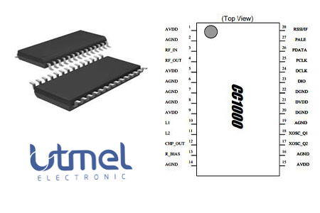
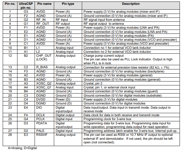
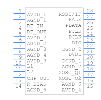
CC1000-RTB1 CAD Model
Symbol
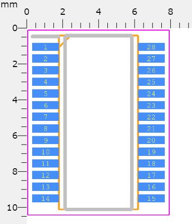
Footprint
3D Model
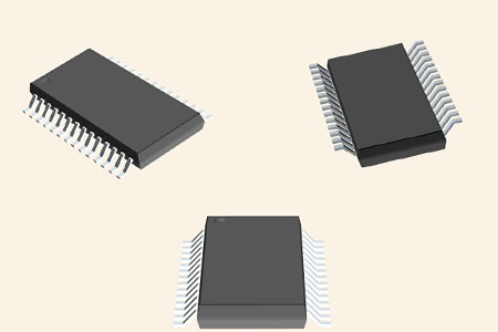
CC1000-RTB1 Description
The CC1000-RTB1 is a true single-chip UHF transceiver designed for very low power and very low voltage wireless application, which is based on Chipcon’s SmartRF® technology in 0.35 µm CMOS.
CC1000-RTB1 Features
• True single-chip UHF RF transceiver
• Very low current consumption
• Frequency range 300 – 1000 MHz
• Integrated bit synchroniser
• High sensitivity (typical -110 dBm at 2.4 kBaud)
• Programmable output power –20 to 10 dBm
• Small size (TSSOP-28 or UltraCSP™ package)
• Low supply voltage (2.1 V to 3.6 V)
• Very few external components required
• No external RF switch / IF filter required
• RSSI output
• Single port antenna connection
• FSK data rate up to 76.8 kBaud
• Complies with EN 300 220 and FCC CFR47 part 15
• Programmable frequency in 250 Hz steps makes crystal temperature drift compensation possible without TCXO
• Suitable for frequency hopping protocols
• Development kit available
• Easy-to-use software for generating the CC1000 configuration data
CC1000-RTB1 Block Diagram
The simplified block diagram for CC1000-RTB1 is shown below.
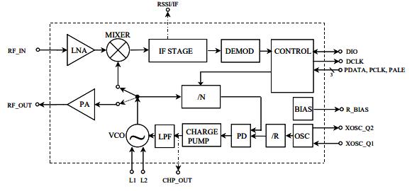
In receive mode, CC1000-RTB1 is configured as a traditional superheterodyne receiver. In transmit mode the voltage-controlled oscillator (VCO) output signal is fed directly to the power amplifier (PA). The frequency synthesiser generates the local oscillator signal which is fed to the MIXER in receive mode and to the PA in transmit mode. The 3-wire digital serial interface (CONTROL) is used for configuration.
Specifications
- TypeParameter
- Lifecycle Status
Lifecycle Status refers to the current stage of an electronic component in its product life cycle, indicating whether it is active, obsolete, or transitioning between these states. An active status means the component is in production and available for purchase. An obsolete status indicates that the component is no longer being manufactured or supported, and manufacturers typically provide a limited time frame for support. Understanding the lifecycle status is crucial for design engineers to ensure continuity and reliability in their projects.
NRND (Last Updated: 1 week ago) - Contact Plating
Contact plating (finish) provides corrosion protection for base metals and optimizes the mechanical and electrical properties of the contact interfaces.
Gold - Mount
In electronic components, the term "Mount" typically refers to the method or process of physically attaching or fixing a component onto a circuit board or other electronic device. This can involve soldering, adhesive bonding, or other techniques to secure the component in place. The mounting process is crucial for ensuring proper electrical connections and mechanical stability within the electronic system. Different components may have specific mounting requirements based on their size, shape, and function, and manufacturers provide guidelines for proper mounting procedures to ensure optimal performance and reliability of the electronic device.
Surface Mount - Mounting Type
The "Mounting Type" in electronic components refers to the method used to attach or connect a component to a circuit board or other substrate, such as through-hole, surface-mount, or panel mount.
Surface Mount - Package / Case
refers to the protective housing that encases an electronic component, providing mechanical support, electrical connections, and thermal management.
28-TSSOP (0.173, 4.40mm Width) - Number of Pins28
- Weight117.508773mg
- Operating Temperature
The operating temperature is the range of ambient temperature within which a power supply, or any other electrical equipment, operate in. This ranges from a minimum operating temperature, to a peak or maximum operating temperature, outside which, the power supply may fail.
-40°C~85°C - Packaging
Semiconductor package is a carrier / shell used to contain and cover one or more semiconductor components or integrated circuits. The material of the shell can be metal, plastic, glass or ceramic.
Tube - JESD-609 Code
The "JESD-609 Code" in electronic components refers to a standardized marking code that indicates the lead-free solder composition and finish of electronic components for compliance with environmental regulations.
e4 - Pbfree Code
The "Pbfree Code" parameter in electronic components refers to the code or marking used to indicate that the component is lead-free. Lead (Pb) is a toxic substance that has been widely used in electronic components for many years, but due to environmental concerns, there has been a shift towards lead-free alternatives. The Pbfree Code helps manufacturers and users easily identify components that do not contain lead, ensuring compliance with regulations and promoting environmentally friendly practices. It is important to pay attention to the Pbfree Code when selecting electronic components to ensure they meet the necessary requirements for lead-free applications.
yes - Part Status
Parts can have many statuses as they progress through the configuration, analysis, review, and approval stages.
Not For New Designs - Moisture Sensitivity Level (MSL)
Moisture Sensitivity Level (MSL) is a standardized rating that indicates the susceptibility of electronic components, particularly semiconductors, to moisture-induced damage during storage and the soldering process, defining the allowable exposure time to ambient conditions before they require special handling or baking to prevent failures
3 (168 Hours) - Number of Terminations28
- TypeTxRx Only
- Voltage - Supply
Voltage - Supply refers to the range of voltage levels that an electronic component or circuit is designed to operate with. It indicates the minimum and maximum supply voltage that can be applied for the device to function properly. Providing supply voltages outside this range can lead to malfunction, damage, or reduced performance. This parameter is critical for ensuring compatibility between different components in a circuit.
2.1V~3.6V - Terminal Position
In electronic components, the term "Terminal Position" refers to the physical location of the connection points on the component where external electrical connections can be made. These connection points, known as terminals, are typically used to attach wires, leads, or other components to the main body of the electronic component. The terminal position is important for ensuring proper connectivity and functionality of the component within a circuit. It is often specified in technical datasheets or component specifications to help designers and engineers understand how to properly integrate the component into their circuit designs.
DUAL - Terminal Form
Occurring at or forming the end of a series, succession, or the like; closing; concluding.
GULL WING - Peak Reflow Temperature (Cel)
Peak Reflow Temperature (Cel) is a parameter that specifies the maximum temperature at which an electronic component can be exposed during the reflow soldering process. Reflow soldering is a common method used to attach electronic components to a circuit board. The Peak Reflow Temperature is crucial because it ensures that the component is not damaged or degraded during the soldering process. Exceeding the specified Peak Reflow Temperature can lead to issues such as component failure, reduced performance, or even permanent damage to the component. It is important for manufacturers and assemblers to adhere to the recommended Peak Reflow Temperature to ensure the reliability and functionality of the electronic components.
260 - Number of Functions1
- Supply Voltage
Supply voltage refers to the electrical potential difference provided to an electronic component or circuit. It is crucial for the proper operation of devices, as it powers their functions and determines performance characteristics. The supply voltage must be within specified limits to ensure reliability and prevent damage to components. Different electronic devices have specific supply voltage requirements, which can vary widely depending on their design and intended application.
3V - Terminal Pitch
The center distance from one pole to the next.
0.65mm - Depth
In electronic components, "Depth" typically refers to the measurement of the distance from the front to the back of the component. It is an important parameter to consider when designing or selecting components for a project, as it determines how much space the component will occupy within a circuit or device. The depth of a component can impact the overall size and layout of the circuit board or enclosure in which it will be installed. It is usually specified in millimeters or inches and is crucial for ensuring proper fit and functionality within the intended application.
4.5mm - Frequency
In electronic components, the parameter "Frequency" refers to the rate at which a signal oscillates or cycles within a given period of time. It is typically measured in Hertz (Hz) and represents how many times a signal completes a full cycle in one second. Frequency is a crucial aspect in electronic components as it determines the behavior and performance of various devices such as oscillators, filters, and communication systems. Understanding the frequency characteristics of components is essential for designing and analyzing electronic circuits to ensure proper functionality and compatibility with other components in a system.
315MHz 433MHz 868MHz 915MHz - Base Part Number
The "Base Part Number" (BPN) in electronic components serves a similar purpose to the "Base Product Number." It refers to the primary identifier for a component that captures the essential characteristics shared by a group of similar components. The BPN provides a fundamental way to reference a family or series of components without specifying all the variations and specific details.
CC1000 - Pin Count
a count of all of the component leads (or pins)
28 - Operating Supply Voltage
The voltage level by which an electrical system is designated and to which certain operating characteristics of the system are related.
3V - Power - Output
Power Output in electronic components refers to the amount of electrical power that a device can deliver to a load. It is typically measured in watts and indicates the effectiveness of the component in converting electrical energy into usable work or signal. Power Output can vary based on the component's design, operating conditions, and intended application, making it a critical factor in the performance of amplifiers, power supplies, and other electronic devices. Understanding the Power Output helps in selecting appropriate components for specific applications to ensure efficiency and reliability.
10dBm Max - RF Family/Standard
The parameter "RF Family/Standard" in electronic components refers to the specific radio frequency (RF) technology or standard that the component complies with or is designed for. RF technology encompasses a wide range of frequencies used for wireless communication, such as Wi-Fi, Bluetooth, cellular networks, and more. Different RF standards dictate the frequency bands, modulation techniques, data rates, and other specifications for communication systems. Understanding the RF family/standard of a component is crucial for ensuring compatibility and optimal performance in RF applications.
General ISM < 1GHz - Data Rate (Max)
Data Rate (Max) refers to the maximum rate at which data can be transferred or processed within an electronic component or device. It is typically measured in bits per second (bps) or megabits per second (Mbps). This parameter is important for determining the speed and efficiency of data transmission or processing in various electronic applications such as computer systems, networking devices, and memory modules. A higher data rate indicates that the component is capable of handling larger volumes of data at a faster pace, leading to improved performance and responsiveness in electronic systems. It is crucial to consider the Data Rate (Max) specification when selecting electronic components to ensure compatibility and optimal functionality for specific applications.
76.8kBaud - Serial Interfaces
A serial interface is a communication interface between two digital systems that transmits data as a series of voltage pulses down a wire. Essentially, the serial interface encodes the bits of a binary number by their "temporal" location on a wire rather than their "spatial" location within a set of wires.
UART - Current - Receiving
Current - Receiving refers to the amount of electrical current that an electronic component or device is capable of accepting from a power source or another component in a circuit. It indicates the maximum current that can be safely received without causing damage or malfunction. This parameter is crucial for ensuring compatibility and reliability in electronic designs, as exceeding the rated receiving current can lead to overheating or failure of the component.
7.4mA~9.6mA - Current - Transmitting
Current - Transmitting is a parameter used to describe the maximum amount of electrical current that an electronic component can handle while in the transmitting mode. This parameter is crucial for components such as transistors, diodes, and integrated circuits that are involved in transmitting signals or power within a circuit. Exceeding the specified current transmitting rating can lead to overheating, component failure, or even damage to the entire circuit. Designers and engineers must carefully consider this parameter when selecting components to ensure the reliability and performance of the electronic system.
5.3mA~26.7mA - Number of Receivers1
- Modulation
In electronic components, modulation refers to the process of varying one or more properties of a periodic waveform, known as the carrier signal, in order to encode information. This modulation technique is commonly used in communication systems to transmit data efficiently over long distances. By modulating the carrier signal, information such as audio, video, or data can be embedded onto the signal for transmission and then demodulated at the receiving end to retrieve the original information. There are various types of modulation techniques, including amplitude modulation (AM), frequency modulation (FM), and phase modulation (PM), each with its own advantages and applications in different communication systems.
FSK - Sensitivity (dBm)
Sensitivity (dBm) is a parameter used to measure the minimum input power level required for an electronic component or device to operate effectively. It is typically expressed in decibels relative to one milliwatt (dBm), which is a common unit of power measurement in the field of electronics. A higher sensitivity value indicates that the component can detect weaker input signals, making it more responsive and capable of functioning in low-power conditions. Sensitivity is an important specification for devices like receivers, sensors, and transducers, as it directly impacts their ability to detect and process signals accurately. Manufacturers often provide sensitivity ratings to help users understand the performance capabilities of the component in different operating conditions.
-110 dBm - Height1.2mm
- Length9.7mm
- Width4.4mm
- Thickness
Thickness in electronic components refers to the measurement of how thick a particular material or layer is within the component structure. It can pertain to various aspects, such as the thickness of a substrate, a dielectric layer, or conductive traces. This parameter is crucial as it impacts the electrical, mechanical, and thermal properties of the component, influencing its performance and reliability in electronic circuits.
1mm - REACH SVHC
The parameter "REACH SVHC" in electronic components refers to the compliance with the Registration, Evaluation, Authorization, and Restriction of Chemicals (REACH) regulation regarding Substances of Very High Concern (SVHC). SVHCs are substances that may have serious effects on human health or the environment, and their use is regulated under REACH to ensure their safe handling and minimize their impact.Manufacturers of electronic components need to declare if their products contain any SVHCs above a certain threshold concentration and provide information on the safe use of these substances. This information allows customers to make informed decisions about the potential risks associated with using the components and take appropriate measures to mitigate any hazards.Ensuring compliance with REACH SVHC requirements is essential for electronics manufacturers to meet regulatory standards, protect human health and the environment, and maintain transparency in their supply chain. It also demonstrates a commitment to sustainability and responsible manufacturing practices in the electronics industry.
No SVHC - Radiation Hardening
Radiation hardening is the process of making electronic components and circuits resistant to damage or malfunction caused by high levels of ionizing radiation, especially for environments in outer space (especially beyond the low Earth orbit), around nuclear reactors and particle accelerators, or during nuclear accidents or nuclear warfare.
No - RoHS Status
RoHS means “Restriction of Certain Hazardous Substances” in the “Hazardous Substances Directive” in electrical and electronic equipment.
ROHS3 Compliant - Lead Free
Lead Free is a term used to describe electronic components that do not contain lead as part of their composition. Lead is a toxic material that can have harmful effects on human health and the environment, so the electronics industry has been moving towards lead-free components to reduce these risks. Lead-free components are typically made using alternative materials such as silver, copper, and tin. Manufacturers must comply with regulations such as the Restriction of Hazardous Substances (RoHS) directive to ensure that their products are lead-free and environmentally friendly.
Contains Lead
CC1000-RTB1 Application
• Very low power UHF wireless data transmitters and receivers
• 315 / 433 / 868 and 915 MHz ISM/SRD band systems
• RKE – Two-way Remote Keyless Entry
• Home automation
• Wireless alarm and security systems
• AMR – Automatic Meter Reading
• Low power telemetry
• Game Controllers and advanced toys
CC1000-RTB1 Typical Application Circuit
The CC1000-RTB1 is very flexible and easy to use because of its main operating parameters. The typical circuit for CC1000-RTB1 is shown below.
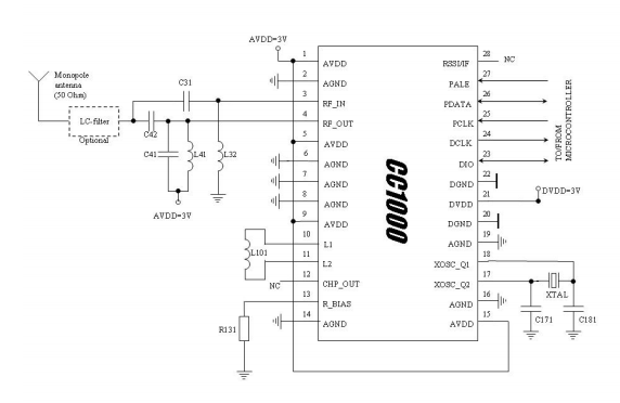
The circuit is mainly intended for the ISM (Industrial, Scientific and Medical) and SRD (Short Range Device) frequency bands at 315, 433, 868 and 915 MHz, but can easily be programmed for operation at other frequencies in the 300-1000 MHz range.
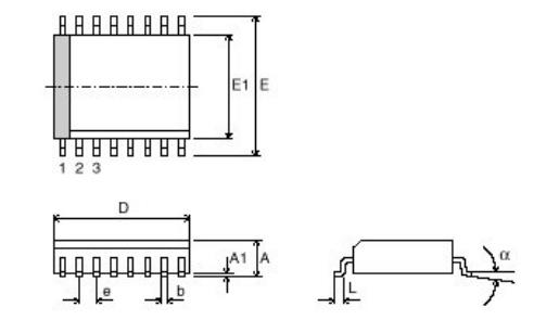
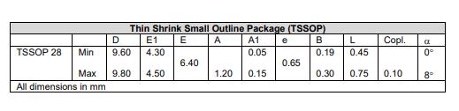
CC1000-RTB1 Package
CC1000-RTB1 Manufacturer
As a global semiconductor company operating in 35 countries, Texas Instruments (TI) is first and foremost a reflection of its people. From the TIer who unveiled the first working integrated circuit in 1958 to the more than 30,000 TIers around the world today who design, manufacture and sell analogue and embedded processing chips, TIers are problem-solvers collaborating to change the world through technology.
Datasheet PDF
- Datasheets :
Popularity by Region
What system will be CC1000-RTB1 use together with a microcontroller and a few external passive components?
In a typical system, CC1000-RTB1 will be used together with a microcontroller and a few external passive components.
What do make CC1000 a very flexible and easy to use transceiver?
The main operating parameters of CC1000 can be programmed via a serial bus, thus making CC1000 a very flexible and easy to use transceiver.
What package is CC1000-RTB1 available in?
CC1000-RTB1 is available in 28-TSSOP (0.173, 4.40mm Width).
 1N4001 Diodes: Pinout, Datasheet and Alternatives
06 July 202111349
![CR2450 VS LIR2450[FAQ+Video]: Are they interchangeable?](https://res.utmel.com/Images/Article/56345724-9bb7-4925-8d33-c37e9926e581.jpg) CR2450 VS LIR2450[FAQ+Video]: Are they interchangeable?
CR2450 VS LIR2450[FAQ+Video]: Are they interchangeable?22 April 20227665
 MCP73831T Controller: Pinout, Datasheet and Circuit
22 July 20211255
![ATTINY45-20PU AVR series Microcontroller IC 8-Bit 20MHz[FAQ]: Datasheet, Features, and Pinout](https://res.utmel.com/Images/Article/a56c3c5f-b7ab-4a23-b644-a7088ffc38d8.jpg) ATTINY45-20PU AVR series Microcontroller IC 8-Bit 20MHz[FAQ]: Datasheet, Features, and Pinout
ATTINY45-20PU AVR series Microcontroller IC 8-Bit 20MHz[FAQ]: Datasheet, Features, and Pinout18 March 20221356
 STM32F103xx Performance Line Microcontroller: A Comprehensive Technical Examination
29 February 2024215
 TLC274 Quad Op-Amp Design Notes: Overcoming Single-Supply Swing Limitations
03 June 2026289
 AD719x Series 24-Bit ADC: Low-Noise Performance Analysis and SPI Implementation Guide
03 March 2026287
 MV104 Diode: Datasheet, Alternatives and Application Circuit
23 September 20211425
 How Proper Thermal Management Extends the Life of Your Electronics
18 July 20251969
 Infrared Thermometer: How it Works? How to Use it?
12 August 20219577
 Low Temperature Drift Resistors Increase the Accuracy of Analog Circuits
11 February 20251698
 What are Fiber Optic Patch Cables?
11 February 20228386
 A/D Converter: Basic Principle and Types
06 November 202020847
 What is an LTPO Display?
08 October 20219181
 Parallel Plate Capacitor: Features, Working Principle and Applications
30 January 20218961
 Understanding the Low Noise Amplifier (LNA)
20 March 202526141
Texas Instruments
In Stock: 60
Minimum: 1 Multiples: 1
Qty
Unit Price
Ext Price
1
$13.604788
$13.60
10
$12.834706
$128.35
100
$12.108213
$1,210.82
500
$11.422842
$5,711.42
1000
$10.776266
$10,776.27
Not the price you want? Send RFQ Now and we'll contact you ASAP.
Inquire for More Quantity
![CC1310F128RGZT]() CC1310F128RGZT
CC1310F128RGZTTexas Instruments
![CC2650F128RSMT]() CC2650F128RSMT
CC2650F128RSMTTexas Instruments
![CC1101RGPR]() CC1101RGPR
CC1101RGPRTexas Instruments
![CC1125RHBR]() CC1125RHBR
CC1125RHBRTexas Instruments
![CC1110F32RHHR]() CC1110F32RHHR
CC1110F32RHHRTexas Instruments
![CC430F5137IRGZR]() CC430F5137IRGZR
CC430F5137IRGZRTexas Instruments
![CC2540F256RHAR]() CC2540F256RHAR
CC2540F256RHARTexas Instruments
![CC1310F128RHBR]() CC1310F128RHBR
CC1310F128RHBRTexas Instruments
![CC2640F128RHBR]() CC2640F128RHBR
CC2640F128RHBRTexas Instruments
![CC2564BRVMT]() CC2564BRVMT
CC2564BRVMTTexas Instruments


