
 Product
 Brand
Brand Articles
 Tools
Tools
CD4060 Binary Counter: Datasheet, Pinout, Circuit

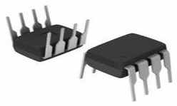
5V DUAL Counters & Dividers 4000B Series 4060 Up Negative Edge 16-DIP (0.300, 7.62mm)


5V DUAL Counters & Dividers 4000B Series 4060 Up Negative Edge 16-DIP (0.300, 7.62mm)
The CD4060 is a 14-stage counter and the counter is a binary ripple carry type. This article will unlock more details about CD4060. There is a huge range of Semiconductors, Capacitors, Resistors and ICs in stock.

CD4060 14-stage Binary Counter to design timing delay circuits
CD4060 Pinout

CD4060 Pinout
| Pin No | Pin Name | Pin Description |
| 7,5,4,6,14,13,15,1,2,3 | Q3, Q4, Q5, Q6, Q7, Q8, Q9, Q11, Q12, A13 | Output pins of the Binary counter |
| 11 | RS | Clock Input Pin for setting the clock frequency |
| 12 | MR | Master Reset |
| 9 | CEXT/ | External Capacitor to set the clock frequency |
| 10 | REXT/ | External Resistor to set the clock frequency |
| 8 | Vss/Ground | Connected to the ground of the system |
| 16 | Vdd | Supply Voltage |
CD4060 CAD Model
Symbol

CD4060 Symbol
Footprint

CD4060 Footprint
3D Model

CD4060 3D Model
CD4060 Description
The CD4060 IC is a 14-stage counter with a binary ripple-carry counter. It's a binary counter using CMOS circuitry that's part of the CD4000 line of integrated circuits. A 14-stage ripple carries binary counter and an internal oscillator make up the circuit. We can also use RC circuits or an external crystal to configure crystal oscillators. It also includes a reset circuit that allows the counter to be reset to zero. It works with a power supply ranging from 3 to 15 volts. It comes in a number of 16-pin packages, including PDIP, CDIP, SOIC, and TSSOP.
Specifications
- TypeParameter
- Mount
In electronic components, the term "Mount" typically refers to the method or process of physically attaching or fixing a component onto a circuit board or other electronic device. This can involve soldering, adhesive bonding, or other techniques to secure the component in place. The mounting process is crucial for ensuring proper electrical connections and mechanical stability within the electronic system. Different components may have specific mounting requirements based on their size, shape, and function, and manufacturers provide guidelines for proper mounting procedures to ensure optimal performance and reliability of the electronic device.
Through Hole - Mounting Type
The "Mounting Type" in electronic components refers to the method used to attach or connect a component to a circuit board or other substrate, such as through-hole, surface-mount, or panel mount.
Through Hole - Package / Case
refers to the protective housing that encases an electronic component, providing mechanical support, electrical connections, and thermal management.
16-DIP (0.300, 7.62mm) - Number of Pins16
- Clock-Edge Trigger TypeNegative Edge
- Number of Elements1
- Operating Temperature
The operating temperature is the range of ambient temperature within which a power supply, or any other electrical equipment, operate in. This ranges from a minimum operating temperature, to a peak or maximum operating temperature, outside which, the power supply may fail.
-55°C~125°C - Packaging
Semiconductor package is a carrier / shell used to contain and cover one or more semiconductor components or integrated circuits. The material of the shell can be metal, plastic, glass or ceramic.
Tube - Series
In electronic components, the "Series" refers to a group of products that share similar characteristics, designs, or functionalities, often produced by the same manufacturer. These components within a series typically have common specifications but may vary in terms of voltage, power, or packaging to meet different application needs. The series name helps identify and differentiate between various product lines within a manufacturer's catalog.
4000B - Published2007
- Part Status
Parts can have many statuses as they progress through the configuration, analysis, review, and approval stages.
Obsolete - Moisture Sensitivity Level (MSL)
Moisture Sensitivity Level (MSL) is a standardized rating that indicates the susceptibility of electronic components, particularly semiconductors, to moisture-induced damage during storage and the soldering process, defining the allowable exposure time to ambient conditions before they require special handling or baking to prevent failures
1 (Unlimited) - Number of Terminations16
- Voltage - Supply
Voltage - Supply refers to the range of voltage levels that an electronic component or circuit is designed to operate with. It indicates the minimum and maximum supply voltage that can be applied for the device to function properly. Providing supply voltages outside this range can lead to malfunction, damage, or reduced performance. This parameter is critical for ensuring compatibility between different components in a circuit.
3V~15V - Terminal Position
In electronic components, the term "Terminal Position" refers to the physical location of the connection points on the component where external electrical connections can be made. These connection points, known as terminals, are typically used to attach wires, leads, or other components to the main body of the electronic component. The terminal position is important for ensuring proper connectivity and functionality of the component within a circuit. It is often specified in technical datasheets or component specifications to help designers and engineers understand how to properly integrate the component into their circuit designs.
DUAL - Number of Functions1
- Supply Voltage
Supply voltage refers to the electrical potential difference provided to an electronic component or circuit. It is crucial for the proper operation of devices, as it powers their functions and determines performance characteristics. The supply voltage must be within specified limits to ensure reliability and prevent damage to components. Different electronic devices have specific supply voltage requirements, which can vary widely depending on their design and intended application.
5V - Terminal Pitch
The center distance from one pole to the next.
2.54mm - Frequency
In electronic components, the parameter "Frequency" refers to the rate at which a signal oscillates or cycles within a given period of time. It is typically measured in Hertz (Hz) and represents how many times a signal completes a full cycle in one second. Frequency is a crucial aspect in electronic components as it determines the behavior and performance of various devices such as oscillators, filters, and communication systems. Understanding the frequency characteristics of components is essential for designing and analyzing electronic circuits to ensure proper functionality and compatibility with other components in a system.
12MHz - Base Part Number
The "Base Part Number" (BPN) in electronic components serves a similar purpose to the "Base Product Number." It refers to the primary identifier for a component that captures the essential characteristics shared by a group of similar components. The BPN provides a fundamental way to reference a family or series of components without specifying all the variations and specific details.
4060 - Supply Voltage-Min (Vsup)
The parameter "Supply Voltage-Min (Vsup)" in electronic components refers to the minimum voltage level required for the component to operate within its specified performance range. This parameter indicates the lowest voltage that can be safely applied to the component without risking damage or malfunction. It is crucial to ensure that the supply voltage provided to the component meets or exceeds this minimum value to ensure proper functionality and reliability. Failure to adhere to the specified minimum supply voltage may result in erratic behavior, reduced performance, or even permanent damage to the component.
3V - Propagation Delay
the flight time of packets over the transmission link and is limited by the speed of light.
1.3 μs - Turn On Delay Time
Turn-on delay, td(on), is the time taken to charge the input capacitance of the device before drain current conduction can start.
1.3 μs - Reset
The "Reset" parameter in electronic components refers to a function that initializes or sets a device to a predefined state. It is often used to clear any temporary data, errors, or configurations that may have been stored during operation. The reset process can ensure that the device starts from a known good state, allowing for reliable performance in subsequent tasks. This parameter is critical in digital circuits and systems where proper initialization is necessary for correct functioning.
Asynchronous - Logic Function
In electronic components, the term "Logic Function" refers to the specific operation or behavior of a component based on its input signals. It describes how the component processes the input signals to produce the desired output. Logic functions are fundamental to digital circuits and are used to perform logical operations such as AND, OR, NOT, and XOR.Each electronic component, such as logic gates or flip-flops, is designed to perform a specific logic function based on its internal circuitry. By understanding the logic function of a component, engineers can design and analyze complex digital systems to ensure proper functionality and performance. Different logic functions can be combined to create more complex operations, allowing for the creation of sophisticated digital devices and systems.
Counter - Direction
In electronic components, the parameter "Direction" refers to the orientation or alignment in which the component is designed to operate effectively. This parameter is particularly important for components such as diodes, transistors, and capacitors, which have specific polarity or orientation requirements for proper functionality. For example, diodes allow current flow in one direction only, so their direction parameter indicates the correct orientation for current flow. Similarly, polarized capacitors have a positive and negative terminal, requiring proper alignment for correct operation. Understanding and adhering to the direction parameter is crucial for ensuring the reliable and efficient performance of electronic components in a circuit.
Up - Logic Type
Logic Type in electronic components refers to the classification of circuits based on the logical operations they perform. It includes types such as AND, OR, NOT, NAND, NOR, XOR, and XNOR, each defining the relationship between binary inputs and outputs. The logic type determines how the inputs affect the output state based on specific rules of Boolean algebra. This classification is crucial for designing digital circuits and systems, enabling engineers to select appropriate components for desired functionalities.
Binary Counter - Number of Bits per Element14
- Trigger Type
Trigger Type in electronic components refers to the mechanism or method by which a device, such as a flip-flop or timer, responds to an input signal. It defines how the device transitions between states based on specific conditions, such as rising or falling edges of a signal, levels, or pulses. Different trigger types such as edge-triggered, level-triggered, or pulse-triggered influence the timing and behavior of the circuit, thereby determining how input signals affect the output in various applications.
Negative Edge - fmax-Min
fmax-Min refers to the frequency range that an electronic component or system can operate within. It represents the difference between the maximum frequency (fmax) and the minimum frequency (Min) limits of operation. This parameter is crucial in defining the bandwidth of the component, indicating how effectively it can transmit or receive signals over that range. A wider fmax-Min value typically signifies better performance for applications that require broad frequency response.
4 MHz - Height Seated (Max)
Height Seated (Max) is a parameter in electronic components that refers to the maximum allowable height of the component when it is properly seated or installed on a circuit board or within an enclosure. This specification is crucial for ensuring proper fit and alignment within the overall system design. Exceeding the maximum seated height can lead to mechanical interference, electrical shorts, or other issues that may impact the performance and reliability of the electronic device. Manufacturers provide this information to help designers and engineers select components that will fit within the designated space and function correctly in the intended application.
5.08mm - Width7.62mm
- REACH SVHC
The parameter "REACH SVHC" in electronic components refers to the compliance with the Registration, Evaluation, Authorization, and Restriction of Chemicals (REACH) regulation regarding Substances of Very High Concern (SVHC). SVHCs are substances that may have serious effects on human health or the environment, and their use is regulated under REACH to ensure their safe handling and minimize their impact.Manufacturers of electronic components need to declare if their products contain any SVHCs above a certain threshold concentration and provide information on the safe use of these substances. This information allows customers to make informed decisions about the potential risks associated with using the components and take appropriate measures to mitigate any hazards.Ensuring compliance with REACH SVHC requirements is essential for electronics manufacturers to meet regulatory standards, protect human health and the environment, and maintain transparency in their supply chain. It also demonstrates a commitment to sustainability and responsible manufacturing practices in the electronics industry.
No SVHC - RoHS Status
RoHS means “Restriction of Certain Hazardous Substances” in the “Hazardous Substances Directive” in electrical and electronic equipment.
RoHS Compliant - Lead Free
Lead Free is a term used to describe electronic components that do not contain lead as part of their composition. Lead is a toxic material that can have harmful effects on human health and the environment, so the electronics industry has been moving towards lead-free components to reduce these risks. Lead-free components are typically made using alternative materials such as silver, copper, and tin. Manufacturers must comply with regulations such as the Restriction of Hazardous Substances (RoHS) directive to ensure that their products are lead-free and environmentally friendly.
Lead Free
CD4060 Feature
Schmitt triggered inputs which allow unlimited rise and fall times
Fully Static operation with buffered inputs and outputs
Counting range: 0 to 16383 (In decimal)
The maximum Clock Frequency is 30MHz at 15V
Medium speed operation: 8MHz type. at VDD = 10V
Pins and function compatible with TTL series
Reset Propagation Delay: 25ns at 5V
RC Oscillator Frequency of 690kHz Min. at 15V
CD4060 Application
Timers
Time Delay Circuits for creating long time delays
Frequency divider
counter circuit
CD4060 Schematic

CD4060 Schematic
CD4060 Alternatives
The Alternative parts for CD4060:
CD4024B(7-bit)
CD4024B(12-bit)
Where to use CD4060
The CD4060 is a 14-bit Binary Counter IC. It has 12 output pins ranging from Q1 to Q14, with Q2 and Q3 being the exceptions. When the pin receives an input clock pulse, the binary value is incremented from 00 0000 0000 0000 to 11 1111 1111 1111, which is equivalent to 0 to 16383 in decimal.
This IC's behaviour can be utilized to make counters and Dividers, and it's also widely used in timing applications. This IC may be of interest to you if you're seeking a 14-bit binary counter that can be incremented by a clock pulse.
How to use CD4060
It's easy to use the CD4060 binary counter IC. Simply supply power to the IC via the Vss and Ground pins; it has a wide operating voltage range of 3V to 18V but is generally used at 5V. Setting your clock frequency is the most crucial step. The internal clock oscillator of the CD4060 can be set using an external resistor (R1) and an external capacitor (C1) as demonstrated in the circuit below.

How to use CD4060
F= 1 / (2.5*R1*C1) is the formula for determining the clock frequency. The unit of F is Hz, whereas the units of R and C are ohms and farads, respectively. We chose a value of 1M for R1 and 0.22uF for the capacitor C1 in our scenario, resulting in a frequency of
F = 1 / (2.5*1000000*0.00000022)
Fosc = 1.8Hz
Similarly, we may get clock pulses of different frequencies by changing the values of R1 and C1. We can compute the time using the calculations below after we get the clock pulse.
T = 25/1.8 = 32/1.8 = 17.7
T = 17.7 seconds
Meaning the output Q5 will go high after 17.7 seconds from resetting the Counter IC.
CD4060 Package

CD4060 Package
CD4060 Manufacturer
On Semiconductor (Nasdaq: ON) is a manufacturer engaging itself in reducing energy use. It features a comprehensive portfolio of power, signal management, and logic, custom solutions that are energy efficient. It acts as a world-class supply chain with high reliability and a network of manufacturing facilities, sales, offices, and design centres in key markets through North America, Europe, and the Asia Pacific regions.
Datasheet PDF
- Datasheets :
- ReachStatement :
Popularity by Region
What package does CD4060 come?
It comes in 16-pin PDIP, CDIP,SOIC, TSSOP packages.
What is the equivalent for CD4060?
The equivalent for CD4060: CD4020, CD4017
How to calculate timing of Output pin?
The frequency of each output pin of CD4060 obtained will be double the previous one. If the frequency at pin 3 is 4Hz, then at pin 2 it will be 8Hz and so on. In addition to it, we can calculate the time period of each pin by this formula:

T = 2^n / fosc
In this formula, fosc is the frequency of the oscillator. In addition, n is the number of the output pin. Consider the case of determining the transition time of pin Q6. As a result, n will be equal to six. Simply enter these values into the calculation above.
T= 2^5/1.8= 64/1.8= 35.5 seconds.
Therefore, we will get a logic high output at pin Q6 after 35.5 seconds.
 J310 Transistor: J310 Pinout, Datasheet, J310 RF Amplifier
13 December 20216936
 LM1458 Dual Op-Amp : Pinout, Applications and Datasheet
10 August 20213511
![NodeMCU ESP8266[Video+FAQ]: ESP32 vs ESP8266](https://res.utmel.com/Images/Article/00a954e3-f3d1-4de7-af46-c84f64cb7130.jpg) NodeMCU ESP8266[Video+FAQ]: ESP32 vs ESP8266
NodeMCU ESP8266[Video+FAQ]: ESP32 vs ESP826604 May 20224770
![Difference Between BC547 Transistor vs. 2N2222 Transistor [Video&FAQ]](https://res.utmel.com/Images/Article/44f9ff79-5120-4f7d-bf83-d8602eca6431.jpg) Difference Between BC547 Transistor vs. 2N2222 Transistor [Video&FAQ]
Difference Between BC547 Transistor vs. 2N2222 Transistor [Video&FAQ]28 August 202338979
 HMC5883L Digital Compass IC: Pinout, Datasheet and Alternatives
06 September 20214244
 2N4401 vs 2N2222: Are They Interchangeable?
24 February 20226765
 ATTINY13V CMOS 8-bit Microcontroller: Features, Pinout and Datasheet
13 January 20221278
 OPA2604 Amplifiers: Schematic, Replacement and Datasheet
18 August 20216842
 How do Inductors Work?
27 October 202516180
 What is a Ceramic Filter?
10 April 20214592
 Dynamic On-Resistance and its Impact on Power Converters
28 August 20232773
 Shift Registers Made Simple for New Learners
15 July 20252369
 Filter Circuit: Types, Characteristics and Principles
01 December 20219298
 What is SPI (Serial Perripheral Interface)?
25 November 20214585
 Understanding Adapter Cards in Modern Computers
05 July 20253296
 Global Ceramic Capacitors Market In-Depth Analysis to 2025
10 December 20256158
ON Semiconductor
In Stock: 35
United States
China
Canada
Japan
Russia
Germany
United Kingdom
Singapore
Italy
Hong Kong(China)
Taiwan(China)
France
Korea
Mexico
Netherlands
Malaysia
Austria
Spain
Switzerland
Poland
Thailand
Vietnam
India
United Arab Emirates
Afghanistan
Åland Islands
Albania
Algeria
American Samoa
Andorra
Angola
Anguilla
Antigua & Barbuda
Argentina
Armenia
Aruba
Australia
Azerbaijan
Bahamas
Bahrain
Bangladesh
Barbados
Belarus
Belgium
Belize
Benin
Bermuda
Bhutan
Bolivia
Bonaire, Sint Eustatius and Saba
Bosnia & Herzegovina
Botswana
Brazil
British Indian Ocean Territory
British Virgin Islands
Brunei
Bulgaria
Burkina Faso
Burundi
Cabo Verde
Cambodia
Cameroon
Cayman Islands
Central African Republic
Chad
Chile
Christmas Island
Cocos (Keeling) Islands
Colombia
Comoros
Congo
Congo (DRC)
Cook Islands
Costa Rica
Côte d’Ivoire
Croatia
Cuba
Curaçao
Cyprus
Czechia
Denmark
Djibouti
Dominica
Dominican Republic
Ecuador
Egypt
El Salvador
Equatorial Guinea
Eritrea
Estonia
Eswatini
Ethiopia
Falkland Islands
Faroe Islands
Fiji
Finland
French Guiana
French Polynesia
Gabon
Gambia
Georgia
Ghana
Gibraltar
Greece
Greenland
Grenada
Guadeloupe
Guam
Guatemala
Guernsey
Guinea
Guinea-Bissau
Guyana
Haiti
Honduras
Hungary
Iceland
Indonesia
Iran
Iraq
Ireland
Isle of Man
Israel
Jamaica
Jersey
Jordan
Kazakhstan
Kenya
Kiribati
Kosovo
Kuwait
Kyrgyzstan
Laos
Latvia
Lebanon
Lesotho
Liberia
Libya
Liechtenstein
Lithuania
Luxembourg
Macao(China)
Madagascar
Malawi
Maldives
Mali
Malta
Marshall Islands
Martinique
Mauritania
Mauritius
Mayotte
Micronesia
Moldova
Monaco
Mongolia
Montenegro
Montserrat
Morocco
Mozambique
Myanmar
Namibia
Nauru
Nepal
New Caledonia
New Zealand
Nicaragua
Niger
Nigeria
Niue
Norfolk Island
North Korea
North Macedonia
Northern Mariana Islands
Norway
Oman
Pakistan
Palau
Palestinian Authority
Panama
Papua New Guinea
Paraguay
Peru
Philippines
Pitcairn Islands
Portugal
Puerto Rico
Qatar
Réunion
Romania
Rwanda
Samoa
San Marino
São Tomé & Príncipe
Saudi Arabia
Senegal
Serbia
Seychelles
Sierra Leone
Sint Maarten
Slovakia
Slovenia
Solomon Islands
Somalia
South Africa
South Sudan
Sri Lanka
St Helena, Ascension, Tristan da Cunha
St. Barthélemy
St. Kitts & Nevis
St. Lucia
St. Martin
St. Pierre & Miquelon
St. Vincent & Grenadines
Sudan
Suriname
Svalbard & Jan Mayen
Sweden
Syria
Tajikistan
Tanzania
Timor-Leste
Togo
Tokelau
Tonga
Trinidad & Tobago
Tunisia
Turkey
Turkmenistan
Turks & Caicos Islands
Tuvalu
U.S. Outlying Islands
U.S. Virgin Islands
Uganda
Ukraine
Uruguay
Uzbekistan
Vanuatu
Vatican City
Venezuela
Wallis & Futuna
Yemen
Zambia
Zimbabwe
![MC74HC4060ADTR2G]() MC74HC4060ADTR2G
MC74HC4060ADTR2GON Semiconductor
![MC14040BDR2G]() MC14040BDR2G
MC14040BDR2GON Semiconductor
![MC14060BDR2G]() MC14060BDR2G
MC14060BDR2GON Semiconductor
![MC74HC390ADR2G]() MC74HC390ADR2G
MC74HC390ADR2GON Semiconductor
![MC14020BDR2G]() MC14020BDR2G
MC14020BDR2GON Semiconductor
![MC74HC393ADR2G]() MC74HC393ADR2G
MC74HC393ADR2GON Semiconductor
![MC14017BDR2G]() MC14017BDR2G
MC14017BDR2GON Semiconductor
![MC14022BDR2G]() MC14022BDR2G
MC14022BDR2GON Semiconductor
![MC14017BDG]() MC14017BDG
MC14017BDGON Semiconductor
![MC74HC4040ADR2G]() MC74HC4040ADR2G
MC74HC4040ADR2GON Semiconductor


