
 Product
 Brand
Brand Articles
 Tools
Tools
TIP29C Transistor: Where & How to Use?


Trans GP BJT NPN 100V 1A 3-Pin(3 Tab) TO-220 Tube
TIP29C is a BJT transistor manufactured in the TO-220 package. This post covers its datasheet, pinout, where and how to use it, so on. More, there is a huge range of Semiconductors, Capacitors, Resistors and ICs in stock. Welcome RFQ!
TIP29C Pinout

TIP29C Pinout
TIP29C CAD Model
Symbol

TDA2004 Symbol
Footprint

TIP29C Footprint
3D Model

TIP29C 3D Model
TIP29C Overview
The TIP29C are manufactured in Planar technology with a “Base Island” layout. The resulting transistor shows exceptional high gain performance coupled with very low saturation voltage.
TIP29C Features:
Package Type: TO-220
Transistor Type: NPN
Max Collector Current(IC): 1A
Max Collector-Emitter Voltage (VCE): 100V
Max Collector-Base Voltage (VCB): 100V
Max Emitter-Base Voltage (VEBO): 5V
Max Collector Dissipation (Pc): 30 Watt
Minimum & Maximum DC Current Gain (hFE): 15 To 75
Max Storage & Operating temperature: -65 to +150 Centigrade
TIP29C Application:
Switching loads under 1A
Simple Audio Amplification
Audio Power Amplifier Circuits
Motor Drivers
TIP29C Equivalents:
2SC1625
2SC1626
BD417
BDT29B
BDT29C
MJE3521
TIP29B
TIP29C Electrical characteristics
Symbol | Parameter | Test Conditions | Min. | Typ. | Max. | Unit |
ICEO | Collector cut-off current | for TIP29A VCE =30V | 0.3 | mA | ||
(IB = 0) | for TIP29C VCE =60V | 0.3 | mA | |||
ICES | Collector cut-off current (VBE = 0) | for TIP29A VCE =60V for TIP29C VCE =100V | 0.2 0.2 | mA mA | ||
IEBO | Emitter cut-off current (IC = 0) | VEB =5V |
1 |
mA | ||
Collector-emitter | IC =30mA | |||||
VCEO(sus)(1) | sustaining voltage (IB = 0) | for TIP29A for TIP29C | 60 100 | V V | ||
VCE(sat)(1) | Collector-emitter saturation voltage | IC =1A IB =125mA | 0.7 | V | ||
V (1) BE | Base-emitter voltage | IC =1A VCE =4V | 1.3 | V | ||
h (1) FE |
DC current gain | IC =0.2A VCE =4V IC =1A VCE =4V | 40 15 |
75 |
Where & How to Use TIP29C?
The TIP29C is a BJT transistor in a TO-220 package. It can be employed in a variety of general-purpose applications that meet its requirements. The transistor's maximum continuous collector current is 1A, implying that it can drive a load of up to 1A constantly at a maximum load voltage of 100V. The transistor's peak collector current can reach 3A. The transistor's collector-emitter saturation value is 0.7V, which implies the transistor will require a minimum voltage of 0.7V or 700mV at its base to allow current to flow from collector to emitter, or ON condition. To get max 1A from the collector the base current should be 125mA. The max collector dissipation of the transistor is 30 Watts and the max DC current gain of the transistor is 75.
TIP29C transistors are suitable for a wide range of switching and amplification applications. This transistor can drive a load of up to 1A when used as a switch, which is sufficient to power electronic relays, LEDs, other power transistors, ICs, and other circuit components. This transistor can be used as a standalone amplifier or as part of an amplifier's stage.
How to Safely Long Run in a Circuit?
Stay 20% below the TIP29C transistor's maximum ratings for long-term performance. Because the transistor's maximum collector current is 1A, do not drive loads that draw more than 800mA. Because the transistor's maximum load voltage is 100V, do not drive loads that are higher than 80V. Always store or use the transistor at temperatures above -65 degrees Celsius and below +150 degrees Celsius, and use an appropriate heatsink with it.
How to Package TIP29C?


TIP29C Package
Datasheet PDF
- Datasheets :
Specifications
- TypeParameter
- Lifecycle Status
Lifecycle Status refers to the current stage of an electronic component in its product life cycle, indicating whether it is active, obsolete, or transitioning between these states. An active status means the component is in production and available for purchase. An obsolete status indicates that the component is no longer being manufactured or supported, and manufacturers typically provide a limited time frame for support. Understanding the lifecycle status is crucial for design engineers to ensure continuity and reliability in their projects.
ACTIVE (Last Updated: 7 months ago) - Factory Lead Time8 Weeks
- Mount
In electronic components, the term "Mount" typically refers to the method or process of physically attaching or fixing a component onto a circuit board or other electronic device. This can involve soldering, adhesive bonding, or other techniques to secure the component in place. The mounting process is crucial for ensuring proper electrical connections and mechanical stability within the electronic system. Different components may have specific mounting requirements based on their size, shape, and function, and manufacturers provide guidelines for proper mounting procedures to ensure optimal performance and reliability of the electronic device.
Through Hole - Mounting Type
The "Mounting Type" in electronic components refers to the method used to attach or connect a component to a circuit board or other substrate, such as through-hole, surface-mount, or panel mount.
Through Hole - Package / Case
refers to the protective housing that encases an electronic component, providing mechanical support, electrical connections, and thermal management.
TO-220-3 - Number of Pins3
- Weight9.071847g
- Transistor Element Material
The "Transistor Element Material" parameter in electronic components refers to the material used to construct the transistor within the component. Transistors are semiconductor devices that amplify or switch electronic signals and are a fundamental building block in electronic circuits. The material used for the transistor element can significantly impact the performance and characteristics of the component. Common materials used for transistor elements include silicon, germanium, and gallium arsenide, each with its own unique properties and suitability for different applications. The choice of transistor element material is crucial in designing electronic components to meet specific performance requirements such as speed, power efficiency, and temperature tolerance.
SILICON - Collector-Emitter Breakdown Voltage100V
- Collector-Emitter Saturation Voltage700mV
- Number of Elements1
- hFEMin15
- Operating Temperature
The operating temperature is the range of ambient temperature within which a power supply, or any other electrical equipment, operate in. This ranges from a minimum operating temperature, to a peak or maximum operating temperature, outside which, the power supply may fail.
150°C TJ - Packaging
Semiconductor package is a carrier / shell used to contain and cover one or more semiconductor components or integrated circuits. The material of the shell can be metal, plastic, glass or ceramic.
Tube - JESD-609 Code
The "JESD-609 Code" in electronic components refers to a standardized marking code that indicates the lead-free solder composition and finish of electronic components for compliance with environmental regulations.
e3 - Part Status
Parts can have many statuses as they progress through the configuration, analysis, review, and approval stages.
Active - Moisture Sensitivity Level (MSL)
Moisture Sensitivity Level (MSL) is a standardized rating that indicates the susceptibility of electronic components, particularly semiconductors, to moisture-induced damage during storage and the soldering process, defining the allowable exposure time to ambient conditions before they require special handling or baking to prevent failures
1 (Unlimited) - Number of Terminations3
- ECCN Code
An ECCN (Export Control Classification Number) is an alphanumeric code used by the U.S. Bureau of Industry and Security to identify and categorize electronic components and other dual-use items that may require an export license based on their technical characteristics and potential for military use.
EAR99 - Terminal Finish
Terminal Finish refers to the surface treatment applied to the terminals or leads of electronic components to enhance their performance and longevity. It can improve solderability, corrosion resistance, and overall reliability of the connection in electronic assemblies. Common finishes include nickel, gold, and tin, each possessing distinct properties suitable for various applications. The choice of terminal finish can significantly impact the durability and effectiveness of electronic devices.
Matte Tin (Sn) - Voltage - Rated DC
Voltage - Rated DC is a parameter that specifies the maximum direct current (DC) voltage that an electronic component can safely handle without being damaged. This rating is crucial for ensuring the proper functioning and longevity of the component in a circuit. Exceeding the rated DC voltage can lead to overheating, breakdown, or even permanent damage to the component. It is important to carefully consider this parameter when designing or selecting components for a circuit to prevent any potential issues related to voltage overload.
100V - Max Power Dissipation
The maximum power that the MOSFET can dissipate continuously under the specified thermal conditions.
2W - Current Rating
Current rating is the maximum current that a fuse will carry for an indefinite period without too much deterioration of the fuse element.
1A - Base Part Number
The "Base Part Number" (BPN) in electronic components serves a similar purpose to the "Base Product Number." It refers to the primary identifier for a component that captures the essential characteristics shared by a group of similar components. The BPN provides a fundamental way to reference a family or series of components without specifying all the variations and specific details.
TIP29 - Pin Count
a count of all of the component leads (or pins)
3 - Element Configuration
The distribution of electrons of an atom or molecule (or other physical structure) in atomic or molecular orbitals.
Single - Power Dissipation
the process by which an electronic or electrical device produces heat (energy loss or waste) as an undesirable derivative of its primary action.
2W - Transistor Application
In the context of electronic components, the parameter "Transistor Application" refers to the specific purpose or function for which a transistor is designed and used. Transistors are semiconductor devices that can amplify or switch electronic signals and are commonly used in various electronic circuits. The application of a transistor can vary widely depending on its design and characteristics, such as whether it is intended for audio amplification, digital logic, power control, or radio frequency applications. Understanding the transistor application is important for selecting the right type of transistor for a particular circuit or system to ensure optimal performance and functionality.
SWITCHING - Gain Bandwidth Product
The gain–bandwidth product (designated as GBWP, GBW, GBP, or GB) for an amplifier is the product of the amplifier's bandwidth and the gain at which the bandwidth is measured.
3MHz - Polarity/Channel Type
In electronic components, the parameter "Polarity/Channel Type" refers to the characteristic that determines the direction of current flow or the type of signal that can be accommodated by the component. For components like diodes and transistors, polarity indicates the direction in which current can flow through the component, such as forward bias or reverse bias for diodes. For components like MOSFETs or JFETs, the channel type refers to whether the component is an N-channel or P-channel device, which determines the type of charge carriers that carry current through the component. Understanding the polarity or channel type of a component is crucial for proper circuit design and ensuring that the component is connected correctly to achieve the desired functionality.
NPN - Transistor Type
Transistor type refers to the classification of transistors based on their operation and construction. The two primary types are bipolar junction transistors (BJTs) and field-effect transistors (FETs). BJTs use current to control the flow of current, while FETs utilize voltage to control current flow. Each type has its own subtypes, such as NPN and PNP for BJTs, and MOSFETs and JFETs for FETs, impacting their applications and characteristics in electronic circuits.
NPN - Collector Emitter Voltage (VCEO)
Collector-Emitter Voltage (VCEO) is a key parameter in electronic components, particularly in transistors. It refers to the maximum voltage that can be applied between the collector and emitter terminals of a transistor while the base terminal is open or not conducting. Exceeding this voltage limit can lead to breakdown and potential damage to the transistor. VCEO is crucial for ensuring the safe and reliable operation of the transistor within its specified limits. Designers must carefully consider VCEO when selecting transistors for a circuit to prevent overvoltage conditions that could compromise the performance and longevity of the component.
100V - Max Collector Current
Max Collector Current is a parameter used to specify the maximum amount of current that can safely flow through the collector terminal of a transistor or other electronic component without causing damage. It is typically expressed in units of amperes (A) and is an important consideration when designing circuits to ensure that the component operates within its safe operating limits. Exceeding the specified max collector current can lead to overheating, degradation of performance, or even permanent damage to the component. Designers must carefully consider this parameter when selecting components and designing circuits to ensure reliable and safe operation.
1A - DC Current Gain (hFE) (Min) @ Ic, Vce
The parameter "DC Current Gain (hFE) (Min) @ Ic, Vce" in electronic components refers to the minimum value of the DC current gain, denoted as hFE, under specific operating conditions of collector current (Ic) and collector-emitter voltage (Vce). The DC current gain hFE represents the ratio of the collector current to the base current in a bipolar junction transistor (BJT), indicating the amplification capability of the transistor. The minimum hFE value at a given Ic and Vce helps determine the transistor's performance and efficiency in amplifying signals within a circuit. Designers use this parameter to ensure proper transistor selection and performance in various electronic applications.
15 @ 1A 4V - Current - Collector Cutoff (Max)
The parameter "Current - Collector Cutoff (Max)" refers to the maximum current at which a transistor or other electronic component will cease to conduct current between the collector and emitter terminals. This parameter is important in determining the maximum current that can flow through the component when it is in the cutoff state. Exceeding this maximum cutoff current can lead to malfunction or damage of the component. It is typically specified in the component's datasheet and is crucial for proper circuit design and operation.
300μA - JEDEC-95 Code
JEDEC-95 Code is a standardized identification system used by the Joint Electron Device Engineering Council to categorize and describe semiconductor devices. This code provides a unique alphanumeric identifier for various memory components, ensuring consistency in documentation and communication across the electronics industry. The format includes information about the type, capacity, and technology of the device, facilitating easier specification and understanding for manufacturers and engineers.
TO-220AB - Vce Saturation (Max) @ Ib, Ic
The parameter "Vce Saturation (Max) @ Ib, Ic" in electronic components refers to the maximum voltage drop across the collector-emitter junction when the transistor is in saturation mode. This parameter is specified at a certain base current (Ib) and collector current (Ic) levels. It indicates the minimum voltage required to keep the transistor fully conducting in saturation mode, ensuring that the transistor operates efficiently and does not enter the cutoff region. Designers use this parameter to ensure proper transistor operation and to prevent overheating or damage to the component.
700mV @ 125mA, 1A - Transition Frequency
Transition Frequency in electronic components refers to the frequency at which a device can transition from one state to another, typically defining the upper limit of its operating frequency. It is a critical parameter in determining the speed and performance of active components like transistors and integrated circuits. This frequency is influenced by factors such as capacitance, resistance, and the inherent characteristics of the materials used in the component's construction. Understanding transition frequency is essential for optimizing circuit designs and ensuring reliable signal processing in various applications.
3MHz - Collector Base Voltage (VCBO)
Collector Base Voltage (VCBO) is the maximum allowable voltage that can be applied between the collector and base terminals of a bipolar junction transistor when the emitter is open. It is a critical parameter that determines the voltage rating of the transistor and helps prevent breakdown in the collector-base junction. Exceeding this voltage can lead to permanent damage or failure of the component.
100V - Emitter Base Voltage (VEBO)
Emitter Base Voltage (VEBO) is a parameter used in electronic components, particularly in transistors. It refers to the maximum voltage that can be applied between the emitter and base terminals of a transistor without causing damage to the device. Exceeding this voltage limit can lead to breakdown of the transistor and potential failure. VEBO is an important specification to consider when designing circuits to ensure the proper operation and reliability of the components. It is typically provided in the datasheet of the transistor and should be carefully observed to prevent any potential damage during operation.
5V - VCEsat-Max
VCEsat-Max refers to the maximum collector-emitter saturation voltage of a bipolar junction transistor (BJT) or an insulated gate bipolar transistor (IGBT). It is a crucial parameter that indicates the minimum voltage drop across the collector-emitter junction when the transistor is in saturation mode. This parameter is important for determining the efficiency and performance of the transistor in switching applications. A lower VCEsat-Max value indicates better performance and reduced power losses in the transistor during operation. Designers often consider this parameter when selecting transistors for applications where minimizing power dissipation is critical.
0.7 V - Height9.15mm
- Length10.4mm
- Width4.6mm
- REACH SVHC
The parameter "REACH SVHC" in electronic components refers to the compliance with the Registration, Evaluation, Authorization, and Restriction of Chemicals (REACH) regulation regarding Substances of Very High Concern (SVHC). SVHCs are substances that may have serious effects on human health or the environment, and their use is regulated under REACH to ensure their safe handling and minimize their impact.Manufacturers of electronic components need to declare if their products contain any SVHCs above a certain threshold concentration and provide information on the safe use of these substances. This information allows customers to make informed decisions about the potential risks associated with using the components and take appropriate measures to mitigate any hazards.Ensuring compliance with REACH SVHC requirements is essential for electronics manufacturers to meet regulatory standards, protect human health and the environment, and maintain transparency in their supply chain. It also demonstrates a commitment to sustainability and responsible manufacturing practices in the electronics industry.
No SVHC - Radiation Hardening
Radiation hardening is the process of making electronic components and circuits resistant to damage or malfunction caused by high levels of ionizing radiation, especially for environments in outer space (especially beyond the low Earth orbit), around nuclear reactors and particle accelerators, or during nuclear accidents or nuclear warfare.
No - RoHS Status
RoHS means “Restriction of Certain Hazardous Substances” in the “Hazardous Substances Directive” in electrical and electronic equipment.
ROHS3 Compliant - Lead Free
Lead Free is a term used to describe electronic components that do not contain lead as part of their composition. Lead is a toxic material that can have harmful effects on human health and the environment, so the electronics industry has been moving towards lead-free components to reduce these risks. Lead-free components are typically made using alternative materials such as silver, copper, and tin. Manufacturers must comply with regulations such as the Restriction of Hazardous Substances (RoHS) directive to ensure that their products are lead-free and environmentally friendly.
Lead Free
Parts with Similar Specs
- ImagePart NumberManufacturerMountPackage / CaseCollector Emitter Breakdown VoltageMax Collector CurrentTransition FrequencyCollector Emitter Saturation VoltagehFE MinMax Power DissipationView Compare
![TIP29C]()
TIP29C
Through Hole
TO-220-3
100 V
1 A
3 MHz
700 mV
15
2 W
![TIP41CTU]()
Through Hole
TO-220-3
100 V
6 A
3 MHz
1.5 V
15
2 W
![TIP41C]()
Through Hole
TO-220-3
80 V
2 A
-
700 mV
15
30 W
![BD239BTU]()
Through Hole
TO-220-3
100 V
6 A
-
1.5 V
15
2 W


Trend Analysis
What is the PNP Type of TIP29C?
The PNP types are TIP30A and TIP30C.
What is the max storage and operating temperature of TIP29C?
Max Storage & Operating temperature: -65 to +150 Centigrade.
![Difference Between TDA7293 vs. TDA7294 Audio Amplifier [Video&FAQ]](https://res.utmel.com/Images/Article/41907ba9-f2a7-4f40-a251-a6196e5ae69f.jpg) Difference Between TDA7293 vs. TDA7294 Audio Amplifier [Video&FAQ]
Difference Between TDA7293 vs. TDA7294 Audio Amplifier [Video&FAQ]24 April 202227047
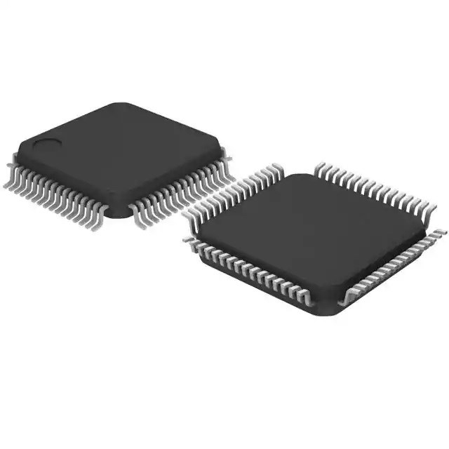
 STM32F405VGT6 Microcontroller: 168MHz, 100-LQFP, Pinout and Datasheet
22 January 20226560
 TPS4H160BQPWPRQ1: 28-PowerTSSOP Package, High-Side Switch, FETs
28 February 2022797
 ULN2004A Darlington Array: Pinout, Equivalent and Datasheet
29 November 20217414
 LM301AN Operational Amplifier: 1MHZ, DIP-8 LM301AN Amplifier, Circuit and Equivalents
11 January 20224571
![MB10F Bridge Stack: Features, Pinout, and Datasheet [Video&FAQ]](https://res.utmel.com/Images/Article/be2ec37f-a7df-40ce-9d94-173c34202fdf.png) MB10F Bridge Stack: Features, Pinout, and Datasheet [Video&FAQ]
MB10F Bridge Stack: Features, Pinout, and Datasheet [Video&FAQ]08 October 202126094
 NCP18XH103F03RB NTC Thermistor 10k 0603: Datasheet, 3D Model, and Application
21 February 20221748
 STM32F410RBT7 Microcontroller: Pinout, Datasheet, and Circuit
30 June 20212319
 Global Power Technology Authorized Distributor | UTMEL Electronics
21 November 20234246
 What is Low Pass Filter
18 November 20217342
 What is Instrument Transformer?
08 January 20227784
 Sourcing for Embodied AI: How Large Action Models (LAMs) are Driving the Edge AI Chip Explosion
22 July 2026125
 PMIC - Gate Drivers: A Purpose-Built Integrated Circuit
22 February 20234151
 Automotive Chips Rose Across the Board!
11 March 20223654
 Electronic components distributor UTMEL to Showcase at electronica China
07 June 20244482
 What is Universal Serial Bus (USB)?
12 June 202612883
STMicroelectronics
In Stock: 2
United States
China
Canada
Japan
Russia
Germany
United Kingdom
Singapore
Italy
Hong Kong(China)
Taiwan(China)
France
Korea
Mexico
Netherlands
Malaysia
Austria
Spain
Switzerland
Poland
Thailand
Vietnam
India
United Arab Emirates
Afghanistan
Åland Islands
Albania
Algeria
American Samoa
Andorra
Angola
Anguilla
Antigua & Barbuda
Argentina
Armenia
Aruba
Australia
Azerbaijan
Bahamas
Bahrain
Bangladesh
Barbados
Belarus
Belgium
Belize
Benin
Bermuda
Bhutan
Bolivia
Bonaire, Sint Eustatius and Saba
Bosnia & Herzegovina
Botswana
Brazil
British Indian Ocean Territory
British Virgin Islands
Brunei
Bulgaria
Burkina Faso
Burundi
Cabo Verde
Cambodia
Cameroon
Cayman Islands
Central African Republic
Chad
Chile
Christmas Island
Cocos (Keeling) Islands
Colombia
Comoros
Congo
Congo (DRC)
Cook Islands
Costa Rica
Côte d’Ivoire
Croatia
Cuba
Curaçao
Cyprus
Czechia
Denmark
Djibouti
Dominica
Dominican Republic
Ecuador
Egypt
El Salvador
Equatorial Guinea
Eritrea
Estonia
Eswatini
Ethiopia
Falkland Islands
Faroe Islands
Fiji
Finland
French Guiana
French Polynesia
Gabon
Gambia
Georgia
Ghana
Gibraltar
Greece
Greenland
Grenada
Guadeloupe
Guam
Guatemala
Guernsey
Guinea
Guinea-Bissau
Guyana
Haiti
Honduras
Hungary
Iceland
Indonesia
Iran
Iraq
Ireland
Isle of Man
Israel
Jamaica
Jersey
Jordan
Kazakhstan
Kenya
Kiribati
Kosovo
Kuwait
Kyrgyzstan
Laos
Latvia
Lebanon
Lesotho
Liberia
Libya
Liechtenstein
Lithuania
Luxembourg
Macao(China)
Madagascar
Malawi
Maldives
Mali
Malta
Marshall Islands
Martinique
Mauritania
Mauritius
Mayotte
Micronesia
Moldova
Monaco
Mongolia
Montenegro
Montserrat
Morocco
Mozambique
Myanmar
Namibia
Nauru
Nepal
New Caledonia
New Zealand
Nicaragua
Niger
Nigeria
Niue
Norfolk Island
North Korea
North Macedonia
Northern Mariana Islands
Norway
Oman
Pakistan
Palau
Palestinian Authority
Panama
Papua New Guinea
Paraguay
Peru
Philippines
Pitcairn Islands
Portugal
Puerto Rico
Qatar
Réunion
Romania
Rwanda
Samoa
San Marino
São Tomé & Príncipe
Saudi Arabia
Senegal
Serbia
Seychelles
Sierra Leone
Sint Maarten
Slovakia
Slovenia
Solomon Islands
Somalia
South Africa
South Sudan
Sri Lanka
St Helena, Ascension, Tristan da Cunha
St. Barthélemy
St. Kitts & Nevis
St. Lucia
St. Martin
St. Pierre & Miquelon
St. Vincent & Grenadines
Sudan
Suriname
Svalbard & Jan Mayen
Sweden
Syria
Tajikistan
Tanzania
Timor-Leste
Togo
Tokelau
Tonga
Trinidad & Tobago
Tunisia
Turkey
Turkmenistan
Turks & Caicos Islands
Tuvalu
U.S. Outlying Islands
U.S. Virgin Islands
Uganda
Ukraine
Uruguay
Uzbekistan
Vanuatu
Vatican City
Venezuela
Wallis & Futuna
Yemen
Zambia
Zimbabwe


