
AD598 LVDT Signal Conditioning: Complete Setup & Calibration Guide


Master the AD598 for LVDT signal conditioning in 3 steps: setup, configure, and calibrate. Achieve precise measurements with this beginner-friendly guide.
Product Introduction
Mastering LVDT signal conditioning becomes straightforward with the AD598. This chip simplifies the process into three essential steps: setup, configuration, and calibration. You can connect, configure, and fine-tune your system without needing advanced technical skills.
The AD598 is a cost-effective option, priced at £56 (excluding VAT), making it accessible for enthusiasts and professionals alike. Its design enables you to focus on precision and performance. This guide provides a practical, step-by-step approach to help you achieve accurate and reliable measurements with ease.
Step 1: Setting Up the AD598
Understanding the AD598 Pinout
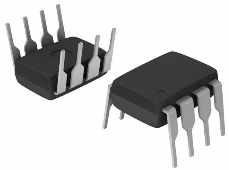
Before you begin, familiarize yourself with the AD598's pinout. This chip has multiple pins, each serving a specific purpose. Knowing their functions ensures proper connections and avoids errors during setup. Key pins include:
Excitation Output Pins: These provide the excitation signal to your LVDT.
Input Pins: These receive the signal from the LVDT's secondary windings.
Output Pins: These deliver the processed signal for further use.
Power Supply Pins: These connect to the power source to energize the chip.
Refer to the datasheet for a detailed pinout diagram. Labeling the pins on your circuit board can help you avoid confusion during wiring.
Power Supply Requirements
The AD598 operates within specific power supply parameters. Providing the correct voltage and current ensures stable performance. Here are the essential specifications:
| Specification | Value |
|---|---|
| Operating Supply Current | 15 mA |
| Operating Supply Voltage | 13 V |
| Supply Voltage - Max | 13 V |
| Supply Voltage - Min | 13 V |
| Minimum Operating Temperature | -40°C |
| Maximum Operating Temperature | +85°C |
Use a regulated power supply to maintain a steady 13 V. Avoid exceeding the maximum voltage to prevent damage. Check the temperature range if you plan to use the AD598 in extreme environments.
Wiring the AD598 to Your LVDT
Connecting the AD598 to your LVDT requires careful attention to detail. Follow these steps to ensure a successful setup:
Connect the Excitation Output: Attach the excitation output pins to the primary winding of your LVDT. The AD598 can generate an excitation voltage between 1 V rms and 24 V rms using an external resistor.
Wire the Secondary Windings: Connect the LVDT's secondary windings to the input pins of the AD598. The chip's signal processing capabilities ensure accurate readings, even with long cables.
Attach the Output Signal: Link the output pins to your measurement system. The AD598 can drive signals over 1000 feet of cable without significant loss.
Verify Connections: Double-check all connections for accuracy. Loose or incorrect wiring can lead to errors or damage.
Tip: Use shielded cables to minimize noise and interference, especially for long-distance connections.
Initial Safety Checks
Before powering up the AD598, you need to perform a series of safety checks to protect your equipment and ensure accurate operation. These steps help you avoid common mistakes and prevent damage to the chip or connected components.
1. Inspect Your Connections
Examine all wiring and connections carefully. Loose wires or incorrect pin assignments can lead to malfunctions or permanent damage. Use a multimeter to check for continuity and confirm that each pin is connected to the correct terminal.
Tip: Label your wires and pins during setup. This makes troubleshooting easier and reduces the risk of errors.
2. Verify Power Supply Parameters
Ensure your power supply matches the AD598's requirements. Set the voltage to exactly 13 V and confirm that the current rating is sufficient. Overvoltage or undervoltage can cause instability or damage.
Use a regulated power supply for consistent output.
Check the voltage with a digital multimeter before connecting the chip.
3. Check for Short Circuits
Inspect your circuit for potential short circuits. These can occur due to soldering errors or exposed wires touching each other. A short circuit can damage the AD598 instantly.
Alert: If you suspect a short circuit, disconnect the power supply immediately and resolve the issue before proceeding.
4. Confirm Environmental Conditions
The AD598 operates within a specific temperature range (-40°C to +85°C). Ensure your workspace is within this range to avoid performance issues. If you're working in a high-temperature environment, consider using cooling solutions.
5. Test the Setup Without Power
Perform a dry run by testing the setup without applying power. Check that the LVDT connections are secure and the output signal path is clear. This step ensures everything is in place before energizing the system.
By following these safety checks, you minimize risks and set the stage for successful operation. Taking a few extra minutes to verify your setup can save you time and prevent costly mistakes.
Step 2: Configuring the AD598 for Your LVDT
Selecting the Excitation Frequency
Choosing the correct excitation frequency is crucial for optimal performance. The AD598 allows you to set this frequency based on your LVDT's specifications. Most LVDTs operate within a range of 1 kHz to 20 kHz. Check your LVDT's datasheet to determine its recommended frequency.
To configure the frequency:
Locate the external resistor pins on the AD598.
Use the formula provided in the datasheet to calculate the resistor value for your desired frequency.
Install the resistor securely to avoid loose connections.
Tip: A stable frequency ensures accurate displacement measurements. Avoid using frequencies outside the LVDT's range, as this can lead to signal distortion.
Adjusting the Excitation Voltage
The AD598 provides flexibility in setting the excitation voltage. This voltage powers the LVDT's primary winding and directly impacts the signal strength. Most LVDTs require an excitation voltage between 1 V rms and 24 V rms.
Follow these steps to adjust the voltage:
Identify the external resistor that controls the excitation voltage.
Refer to the AD598 datasheet for the resistor value corresponding to your desired voltage.
Replace or adjust the resistor as needed.
Note: Higher excitation voltages can improve signal-to-noise ratio but may increase power consumption. Balance voltage settings to match your application needs.
Connecting the Output Signal
Once the excitation settings are configured, connect the output signal to your measurement system. The AD598 processes the LVDT's input signals and provides a clean, linear output.
Steps to connect the output signal:
Locate the output pins on the AD598.
Use shielded cables to connect these pins to your data acquisition system or display device.
Verify the connections to ensure proper polarity and secure attachment.
Alert: Double-check the output connections before powering the system. Incorrect wiring can lead to inaccurate readings or damage to your equipment.
By carefully configuring the excitation frequency, voltage, and output connections, you ensure that the AD598 operates efficiently with your LVDT. These steps lay the foundation for precise and reliable measurements.
Verifying Signal Integrity
Ensuring signal integrity is essential for accurate measurements when using the AD598. This step helps you confirm that the processed output matches the expected performance of your LVDT system. Follow these methods to verify the integrity of your signal.
1. Inspect the Output Signal
Use an oscilloscope or a signal analyzer to examine the output signal. Look for a clean waveform without distortion or noise. A stable signal indicates proper configuration and wiring. If you notice irregularities, check the connections and power supply.
Tip: Place the oscilloscope probes close to the AD598 output pins to minimize interference during testing.
2. Measure Signal Amplitude
Compare the amplitude of the output signal to the expected range specified in your LVDT datasheet. Use a multimeter or signal analyzer for precise readings. If the amplitude deviates significantly, adjust the excitation voltage or gain settings.
3. Test Signal Linearity
Verify that the output signal changes linearly with displacement. Move the LVDT core through its range and record the output values. Plot these values on a graph to check for a straight line. Non-linear behavior may indicate incorrect calibration or wiring issues.
4. Check for Noise Interference
Noise can disrupt signal integrity, especially in environments with electromagnetic interference. Use shielded cables and ensure proper grounding to reduce noise. If interference persists, consider relocating the setup to a quieter area.
Alert: Excessive noise can lead to inaccurate readings. Address this issue promptly to maintain system reliability.
By following these steps, you ensure that the AD598 delivers accurate and reliable signals. Signal integrity verification is a critical step before proceeding to calibration.
Step 3: Calibrating the AD598 for Accurate Measurements
Zeroing the Output Signal
Zeroing the output signal ensures your AD598 delivers accurate readings when the LVDT core is at its neutral position. Begin by setting the LVDT to its zero displacement point. This is typically the position where the core is centered within the primary winding.
Follow these steps to zero the output signal:
Locate the zero adjustment potentiometer on the AD598.
Use a small screwdriver to turn the potentiometer. Adjust it until the output signal reads zero volts.
Monitor the output using a multimeter or oscilloscope to confirm the adjustment.
Tip: Make small, incremental adjustments to avoid overshooting the zero point. If the signal fluctuates, check the wiring and ensure the LVDT is stable.
Zeroing the output signal is a critical step. It eliminates offset errors and provides a baseline for accurate measurements.
Adjusting the Gain
Gain adjustment allows the AD598 to scale the output signal according to your measurement range. This step ensures the signal corresponds accurately to the LVDT's displacement.
To adjust the gain:
Identify the gain adjustment potentiometer on the AD598.
Refer to your LVDT's datasheet to determine the required output range.
Rotate the potentiometer to increase or decrease the gain.
Use the following formula to verify the gain setting:
Output Voltage = Gain × Displacement
Measure the output voltage for a known displacement and compare it to the expected value. Adjust the potentiometer until the values match.
Alert: Excessive gain can amplify noise and distort the signal. Keep the gain within the recommended range for your LVDT.
Proper gain adjustment ensures the AD598 delivers a linear and proportional output, making it easier to interpret displacement measurements.
Testing with Known Displacements
Testing with known displacements validates the calibration process and confirms the AD598 is functioning correctly. Use a displacement test rig or a calibrated micrometer to move the LVDT core through specific positions.
Steps for testing:
Set the LVDT core to a known displacement, such as 0.5 mm or 1 mm.
Record the output voltage from the AD598 using a multimeter or data acquisition system.
Compare the recorded voltage to the expected value based on the gain setting.
Create a table to track your results:
| Displacement (mm) | Expected Voltage (V) | Measured Voltage (V) |
|---|---|---|
| 0.5 | 1.0 | 1.02 |
| 1.0 | 2.0 | 2.01 |
Note: If the measured values deviate significantly, revisit the zeroing and gain adjustment steps.
Testing with known displacements ensures the AD598 provides accurate and reliable measurements. Repeat the test across the LVDT's full range to confirm linearity and performance.
Fine-Tuning for Performance
Fine-tuning the AD598 ensures your LVDT system delivers the best possible performance. This step involves optimizing the system for stability, accuracy, and reliability. By making small adjustments and testing thoroughly, you can achieve precise measurements tailored to your application.
1. Minimize Noise and Interference
Noise can disrupt your system and reduce measurement accuracy. To minimize interference:
Use shielded cables for all connections. These cables block external electromagnetic interference.
Ensure proper grounding of your circuit. A poor ground connection can introduce unwanted noise.
Keep the AD598 and LVDT away from high-power devices or motors. These can generate electromagnetic fields that interfere with your signal.
Tip: If noise persists, try adding a low-pass filter to the output signal. This filter removes high-frequency noise while preserving the measurement signal.
2. Optimize the Excitation Voltage
The excitation voltage directly affects the signal strength and noise levels. Adjust the voltage to balance performance and power consumption. Higher voltages improve the signal-to-noise ratio but may increase heat generation. Lower voltages save power but can reduce signal clarity.
To find the optimal voltage:
Start with the recommended voltage from your LVDT's datasheet.
Gradually increase or decrease the voltage while monitoring the output signal.
Stop adjusting when you achieve a clean, stable signal without excessive noise.
3. Test for Temperature Stability
Temperature changes can affect the AD598's performance. Test your system in the temperature range it will operate in. Monitor the output signal for any drift or instability. If you notice issues, consider using a temperature-compensated LVDT or placing the AD598 in a controlled environment.
Alert: Avoid exposing the AD598 to temperatures outside its operating range (-40°C to +85°C). Extreme temperatures can damage the chip or cause inaccurate readings.
4. Verify Long-Term Stability
Long-term stability ensures your system remains reliable over time. Perform extended tests by running the AD598 continuously for several hours or days. Check the output signal periodically to ensure it remains consistent.
Note: If you notice signal drift, revisit the calibration steps. Small adjustments to the zero or gain settings can correct long-term drift.
5. Document Your Settings
Once you achieve optimal performance, document your settings. Record the excitation voltage, frequency, gain, and any other adjustments you made. This documentation helps you replicate the setup in the future or troubleshoot issues.
| Parameter | Value | Notes |
|---|---|---|
| Excitation Voltage | 10 V rms | Optimal for noise reduction |
| Excitation Frequency | 5 kHz | Matches LVDT specifications |
| Gain Setting | 2.5 | Provides accurate output range |
By fine-tuning the AD598, you ensure your LVDT system operates at peak performance. These adjustments help you achieve accurate, reliable, and repeatable measurements.
Mastering the AD598 for LVDTs involves three straightforward steps: setup, configuration, and calibration. By following this guide, you can ensure your system operates with precision and reliability. Each step builds on the previous one, creating a solid foundation for accurate measurements.
Tip: If you encounter issues, double-check your wiring, power supply, and calibration settings. Small adjustments often resolve common problems.
To optimize performance, document your settings and test your system regularly. With practice, you’ll gain confidence in using the AD598 to achieve consistent results. Start applying these steps today and unlock the full potential of your LVDT system!
FAQ
What is the AD598 used for?
The AD598 is a signal conditioning chip designed for Linear Variable Differential Transformers (LVDTs). It processes signals from LVDTs to provide accurate and linear output, making it ideal for displacement and position measurement applications.
Can I use the AD598 with any LVDT?
Yes, the AD598 works with most LVDTs. However, you must ensure the excitation voltage and frequency match your LVDT's specifications. Always check the datasheet of both the AD598 and your LVDT for compatibility.
How do I calculate the excitation frequency?
You calculate the excitation frequency using a resistor connected to the AD598. The datasheet provides a formula to determine the resistor value based on your desired frequency. Use this formula to set the frequency within your LVDT's operating range.
Why is signal integrity important?
Signal integrity ensures accurate and reliable measurements. Poor signal quality can lead to distorted or noisy outputs. You can maintain integrity by using shielded cables, proper grounding, and verifying connections with tools like oscilloscopes.
What should I do if the output signal is incorrect?
First, check your wiring and power supply. Ensure the excitation voltage and frequency are set correctly. Revisit the zeroing and gain adjustment steps. If the issue persists, inspect for noise interference or consult the AD598 datasheet for troubleshooting tips.
Tip: Document your settings to simplify future troubleshooting.
Specifications
- TypeParameter
Parts with Similar Specs
 BMM150 Sensor: Datasheet, Pinout and Applications
27 August 20213675
 CY8C24794 PSoC™ Microcontroller: In-Depth Technical Analysis
29 February 202492
 LM7809 Voltage Regulator IC: Equivalent, Pinout and Datasheet
14 September 202114137
 H6 vs H7 Battery: Which One Do You Like Better?
01 April 202246718
 Analog Devices Inc. 5962-8851301PA: A Versatile Instrumentation Amplifier for Military Applications
06 March 2024129
 LM393P Dual Comparator: 36V, Pinout, Datasheet
17 March 20226592
 LTC6905IS5-133#TRPBF: Programmable Timer and Oscillator for Precision Timing Applications
06 March 2024183
 AT28C256 150ns Parallel EEPROM: Detailed Pinout, SDP Unlocking, and Retrocomputing Design Guide
10 February 202683
 Texas Semiconductor Summit: A Step Towards Overcoming Chip Shortage
14 October 20231056
 What is 232\485\422 Communication? Common problems of Serial Communication
29 April 20221937
 Lattice FPGA: The Ultimate Guide to Low-Power, Small Form Factor Solutions
19 September 20253302
 Working and Types of Touch Screen
20 March 20215793
 Huawei's Sensor Layout
24 March 20222176
 How Do We Seize Investment Opportunities on the Eve of the Ultimate Human Energy Final?
12 July 2022918
 MLCC: Applications and Future Development
20 December 20217698
 Understanding the Crystal Oscillator: Construction, Working Principles and Applications
08 July 20243124
In Stock
United States
China
Canada
Japan
Russia
Germany
United Kingdom
Singapore
Italy
Hong Kong(China)
Taiwan(China)
France
Korea
Mexico
Netherlands
Malaysia
Austria
Spain
Switzerland
Poland
Thailand
Vietnam
India
United Arab Emirates
Afghanistan
Åland Islands
Albania
Algeria
American Samoa
Andorra
Angola
Anguilla
Antigua & Barbuda
Argentina
Armenia
Aruba
Australia
Azerbaijan
Bahamas
Bahrain
Bangladesh
Barbados
Belarus
Belgium
Belize
Benin
Bermuda
Bhutan
Bolivia
Bonaire, Sint Eustatius and Saba
Bosnia & Herzegovina
Botswana
Brazil
British Indian Ocean Territory
British Virgin Islands
Brunei
Bulgaria
Burkina Faso
Burundi
Cabo Verde
Cambodia
Cameroon
Cayman Islands
Central African Republic
Chad
Chile
Christmas Island
Cocos (Keeling) Islands
Colombia
Comoros
Congo
Congo (DRC)
Cook Islands
Costa Rica
Côte d’Ivoire
Croatia
Cuba
Curaçao
Cyprus
Czechia
Denmark
Djibouti
Dominica
Dominican Republic
Ecuador
Egypt
El Salvador
Equatorial Guinea
Eritrea
Estonia
Eswatini
Ethiopia
Falkland Islands
Faroe Islands
Fiji
Finland
French Guiana
French Polynesia
Gabon
Gambia
Georgia
Ghana
Gibraltar
Greece
Greenland
Grenada
Guadeloupe
Guam
Guatemala
Guernsey
Guinea
Guinea-Bissau
Guyana
Haiti
Honduras
Hungary
Iceland
Indonesia
Iran
Iraq
Ireland
Isle of Man
Israel
Jamaica
Jersey
Jordan
Kazakhstan
Kenya
Kiribati
Kosovo
Kuwait
Kyrgyzstan
Laos
Latvia
Lebanon
Lesotho
Liberia
Libya
Liechtenstein
Lithuania
Luxembourg
Macao(China)
Madagascar
Malawi
Maldives
Mali
Malta
Marshall Islands
Martinique
Mauritania
Mauritius
Mayotte
Micronesia
Moldova
Monaco
Mongolia
Montenegro
Montserrat
Morocco
Mozambique
Myanmar
Namibia
Nauru
Nepal
New Caledonia
New Zealand
Nicaragua
Niger
Nigeria
Niue
Norfolk Island
North Korea
North Macedonia
Northern Mariana Islands
Norway
Oman
Pakistan
Palau
Palestinian Authority
Panama
Papua New Guinea
Paraguay
Peru
Philippines
Pitcairn Islands
Portugal
Puerto Rico
Qatar
Réunion
Romania
Rwanda
Samoa
San Marino
São Tomé & Príncipe
Saudi Arabia
Senegal
Serbia
Seychelles
Sierra Leone
Sint Maarten
Slovakia
Slovenia
Solomon Islands
Somalia
South Africa
South Sudan
Sri Lanka
St Helena, Ascension, Tristan da Cunha
St. Barthélemy
St. Kitts & Nevis
St. Lucia
St. Martin
St. Pierre & Miquelon
St. Vincent & Grenadines
Sudan
Suriname
Svalbard & Jan Mayen
Sweden
Syria
Tajikistan
Tanzania
Timor-Leste
Togo
Tokelau
Tonga
Trinidad & Tobago
Tunisia
Turkey
Turkmenistan
Turks & Caicos Islands
Tuvalu
U.S. Outlying Islands
U.S. Virgin Islands
Uganda
Ukraine
Uruguay
Uzbekistan
Vanuatu
Vatican City
Venezuela
Wallis & Futuna
Yemen
Zambia
Zimbabwe