
 Product
 Brand
Brand Articles
 Tools
Tools
74HC259 8-Bit Addressable Latch : Pinout, Application and Datasheet

Toshiba Semiconductor and Storage
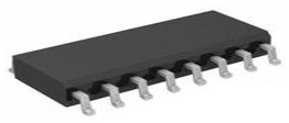
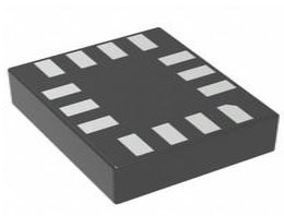
2V~6V 1 Bits Standard Latches 74HC Series DUAL 16-SOIC (0.154, 3.90mm Width)
Unit Price: $0.490838
Ext Price: $0.49


2V~6V 1 Bits Standard Latches 74HC Series DUAL 16-SOIC (0.154, 3.90mm Width)
74HC259 is an 8-bit addressable latch. This article mainly introduce its pinout,application, datasheet and other detailed information about toshiba semiconductor and storage 74HC259.

1-Bit Breadboard Computer P.05 – Output Using a 74HC259 and a New Halt Design
74HC259 Description
The 74HC259 is an 8-bit addressable latch. The device has four modes operation. In the addressable latch mode, the data on the D input is written to the latch addressed by inputs AO to A3. The addressing latch will follow the data input, Latches that are not addressed will retain their previous state. In memory mode, all latches are reserved Their previous state is not affected by data or address input. Between 3 and 8 decoding or demultiplexing mode, addressing output follows D input and all other The output is low. In reset mode, all outputs are forced to low level and are not affected by data or address input. The input includes clamping diodes. This makes it possible to use the current A limiting resistor connects the input to a voltage exceeding VCC.
74HC259 Pinout


74HC259 Features
● Combined demultiplexer and 8-bit latch
● Serial to parallel capability
● Output of each available storage bit
● Random (addressable) data input
● Easy to expand
● Common reset input
● Can be used as 3 to 8 active HIGH decoder
● Comply with JEDEC standard number. 7A
● Input level: CMOS level
● ESD protection:
u HBM JESD22-A114F exceeds 2000 V
u MM JESD22-A115-A over 200 V
u CDM JESD22E exceeds 1000 V
● Multiple package options
● Specified from 40 C to +85 C and from 40 C to +125 C
Specifications
- TypeParameter
- Factory Lead Time12 Weeks
- Mounting Type
The "Mounting Type" in electronic components refers to the method used to attach or connect a component to a circuit board or other substrate, such as through-hole, surface-mount, or panel mount.
Surface Mount - Package / Case
refers to the protective housing that encases an electronic component, providing mechanical support, electrical connections, and thermal management.
16-SOIC (0.154, 3.90mm Width) - Surface Mount
having leads that are designed to be soldered on the side of a circuit board that the body of the component is mounted on.
YES - Operating Temperature
The operating temperature is the range of ambient temperature within which a power supply, or any other electrical equipment, operate in. This ranges from a minimum operating temperature, to a peak or maximum operating temperature, outside which, the power supply may fail.
-40°C~125°C - Packaging
Semiconductor package is a carrier / shell used to contain and cover one or more semiconductor components or integrated circuits. The material of the shell can be metal, plastic, glass or ceramic.
Cut Tape (CT) - Series
In electronic components, the "Series" refers to a group of products that share similar characteristics, designs, or functionalities, often produced by the same manufacturer. These components within a series typically have common specifications but may vary in terms of voltage, power, or packaging to meet different application needs. The series name helps identify and differentiate between various product lines within a manufacturer's catalog.
74HC - Published2016
- Part Status
Parts can have many statuses as they progress through the configuration, analysis, review, and approval stages.
Active - Moisture Sensitivity Level (MSL)
Moisture Sensitivity Level (MSL) is a standardized rating that indicates the susceptibility of electronic components, particularly semiconductors, to moisture-induced damage during storage and the soldering process, defining the allowable exposure time to ambient conditions before they require special handling or baking to prevent failures
1 (Unlimited) - Number of Terminations16
- Voltage - Supply
Voltage - Supply refers to the range of voltage levels that an electronic component or circuit is designed to operate with. It indicates the minimum and maximum supply voltage that can be applied for the device to function properly. Providing supply voltages outside this range can lead to malfunction, damage, or reduced performance. This parameter is critical for ensuring compatibility between different components in a circuit.
2V~6V - Terminal Position
In electronic components, the term "Terminal Position" refers to the physical location of the connection points on the component where external electrical connections can be made. These connection points, known as terminals, are typically used to attach wires, leads, or other components to the main body of the electronic component. The terminal position is important for ensuring proper connectivity and functionality of the component within a circuit. It is often specified in technical datasheets or component specifications to help designers and engineers understand how to properly integrate the component into their circuit designs.
DUAL - Terminal Form
Occurring at or forming the end of a series, succession, or the like; closing; concluding.
GULL WING - Peak Reflow Temperature (Cel)
Peak Reflow Temperature (Cel) is a parameter that specifies the maximum temperature at which an electronic component can be exposed during the reflow soldering process. Reflow soldering is a common method used to attach electronic components to a circuit board. The Peak Reflow Temperature is crucial because it ensures that the component is not damaged or degraded during the soldering process. Exceeding the specified Peak Reflow Temperature can lead to issues such as component failure, reduced performance, or even permanent damage to the component. It is important for manufacturers and assemblers to adhere to the recommended Peak Reflow Temperature to ensure the reliability and functionality of the electronic components.
NOT SPECIFIED - Number of Functions1
- Supply Voltage
Supply voltage refers to the electrical potential difference provided to an electronic component or circuit. It is crucial for the proper operation of devices, as it powers their functions and determines performance characteristics. The supply voltage must be within specified limits to ensure reliability and prevent damage to components. Different electronic devices have specific supply voltage requirements, which can vary widely depending on their design and intended application.
4.5V - Time@Peak Reflow Temperature-Max (s)
Time@Peak Reflow Temperature-Max (s) refers to the maximum duration that an electronic component can be exposed to the peak reflow temperature during the soldering process, which is crucial for ensuring reliable solder joint formation without damaging the component.
NOT SPECIFIED - Output Type
The "Output Type" parameter in electronic components refers to the type of signal or data that is produced by the component as an output. This parameter specifies the nature of the output signal, such as analog or digital, and can also include details about the voltage levels, current levels, frequency, and other characteristics of the output signal. Understanding the output type of a component is crucial for ensuring compatibility with other components in a circuit or system, as well as for determining how the output signal can be utilized or processed further. In summary, the output type parameter provides essential information about the nature of the signal that is generated by the electronic component as its output.
Standard - Circuit
The parameter "Circuit" in electronic components refers to the interconnected arrangement of various electronic elements such as resistors, capacitors, inductors, and active devices like transistors. It defines the path through which electric current flows and establishes the operational behavior of the components within that system. Circuits can be classified as analog or digital, depending on the type of signals they handle, and can vary in complexity from simple series or parallel configurations to intricate designs used in advanced applications.
1:8 - Supply Voltage-Max (Vsup)
The parameter "Supply Voltage-Max (Vsup)" in electronic components refers to the maximum voltage that can be safely applied to the component without causing damage. It is an important specification to consider when designing or using electronic circuits to ensure the component operates within its safe operating limits. Exceeding the maximum supply voltage can lead to overheating, component failure, or even permanent damage. It is crucial to adhere to the specified maximum supply voltage to ensure the reliable and safe operation of the electronic component.
6V - Supply Voltage-Min (Vsup)
The parameter "Supply Voltage-Min (Vsup)" in electronic components refers to the minimum voltage level required for the component to operate within its specified performance range. This parameter indicates the lowest voltage that can be safely applied to the component without risking damage or malfunction. It is crucial to ensure that the supply voltage provided to the component meets or exceeds this minimum value to ensure proper functionality and reliability. Failure to adhere to the specified minimum supply voltage may result in erratic behavior, reduced performance, or even permanent damage to the component.
2V - Number of Bits1
- Family
In electronic components, the parameter "Family" typically refers to a categorization or classification system used to group similar components together based on their characteristics, functions, or applications. This classification helps users easily identify and select components that meet their specific requirements. The "Family" parameter can include various subcategories such as resistors, capacitors, diodes, transistors, integrated circuits, and more. Understanding the "Family" of an electronic component can provide valuable information about its compatibility, performance specifications, and potential uses within a circuit or system. It is important to consider the "Family" parameter when designing or troubleshooting electronic circuits to ensure proper functionality and compatibility with other components.
HC/UH - Logic Type
Logic Type in electronic components refers to the classification of circuits based on the logical operations they perform. It includes types such as AND, OR, NOT, NAND, NOR, XOR, and XNOR, each defining the relationship between binary inputs and outputs. The logic type determines how the inputs affect the output state based on specific rules of Boolean algebra. This classification is crucial for designing digital circuits and systems, enabling engineers to select appropriate components for desired functionalities.
D-Type, Addressable - Output Polarity
Output polarity in electronic components refers to the orientation of the output signal in relation to the ground or reference voltage. It indicates whether the output voltage is positive or negative with respect to the ground. Positive output polarity means the signal is higher than the ground potential, while negative output polarity signifies that the signal is lower than the ground. This characteristic is crucial for determining compatibility with other components in a circuit and ensuring proper signal processing.
TRUE - Trigger Type
Trigger Type in electronic components refers to the mechanism or method by which a device, such as a flip-flop or timer, responds to an input signal. It defines how the device transitions between states based on specific conditions, such as rising or falling edges of a signal, levels, or pulses. Different trigger types such as edge-triggered, level-triggered, or pulse-triggered influence the timing and behavior of the circuit, thereby determining how input signals affect the output in various applications.
LOW LEVEL - Independent Circuits
The term "Independent Circuits" in electronic components refers to the ability of a device to function as a separate and self-contained circuit within a larger system. In the context of electronic components, having independent circuits means that each circuit can operate autonomously without being directly affected by other circuits in the system. This feature allows for better isolation, control, and troubleshooting of individual circuits within a complex electronic system. Independent circuits are commonly found in devices such as integrated circuits, where multiple functional blocks are designed to operate independently to perform specific tasks efficiently. Overall, the presence of independent circuits in electronic components enhances the reliability, flexibility, and performance of the system as a whole.
1 - Delay Time - Propagation
Delay Time - Propagation is a parameter in electronic components that refers to the time it takes for a signal to travel from the input of a component to its output. It is a crucial characteristic in digital circuits as it determines the speed at which signals can propagate through the component. A shorter delay time means faster signal propagation, which is important for ensuring proper timing and performance in electronic systems. Engineers often analyze and optimize delay time propagation to improve the overall speed and efficiency of electronic devices.
22ns - Length9.9mm
- Width3.9mm
- RoHS Status
RoHS means “Restriction of Certain Hazardous Substances” in the “Hazardous Substances Directive” in electrical and electronic equipment.
RoHS Compliant
74HC259 Functional Diagram

Logic Symbol

IEC logic symbol

Functional Diagram
74HC259 System Diagram

74HC259 Alternatives

74HC259 Package Outline

74HC259 Manufacturer
Toshiba Corporation is a Japanese multinational corporation headquartered in Tokyo Minato. Its diversified products and services include power, industrial and social infrastructure systems, elevators and escalators, electronic components, semiconductors, hard disk drives, printers, batteries, lighting, and IT solutions such as quantum cryptography. It is one of the largest manufacturers of personal computers, consumer electronics, household appliances and medical equipment. As a semiconductor company and the inventor of flash memory, Toshiba has been one of the top 10 in the chip industry until its flash memory division was spun off in the late 2010s as Toshiba Memory, which later became Kioxia.
Trend Analysis
Datasheet PDF
- Datasheets :
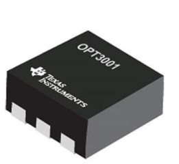 OPT3001DNPT: Light Sensor, Pinout, Circuit
26 March 2022722
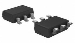 TPS22810DBVR On-Resistance Load Switch: Circuit, Pinout, and Datasheet
24 March 20222711
 CD4027 JK Flip-Flop IC:Pinout, Diagram and Datasheet
12 August 20217413
 LP5018RSMR LED Driver: Datasheet, Alternatives, CAD Models
23 March 20222241
 EPM240T100C5N CPLD: Features, Applications and Datasheet
27 October 20231646
 RP2040 VS ESP8266 VS ESP32 VS STM32
20 April 20229717
 AD9226 65 MSPS 12-bit ADC: High-Speed Data Acquisition and FPGA Integration Guide
14 March 2026373
 LSM6DS3 Accelerometer/ Gyroscope: Datasheet, Pinout and Features
19 August 20216851
 Role of On-Chip Optical Communication in Overcoming CMOS Scaling Challenges
22 August 20242320
 The Practical Engineer’s Guide to the NE555N Timer: Pinout, Setup, and Troubleshooting
29 May 2026194
 Design and Implementation of High Frequency Inverter for Printer Based on IR2110
13 April 20229866
 Low Temperature Drift Resistors Increase the Accuracy of Analog Circuits
11 February 20251548
 Enhancing the Efficiency of Semiconductors by Using the Spin of Electrons
11 February 20251505
 What is a Ground Fault Circuit Interrupter?
27 March 20255433
 Is Electromagnetic Radiation from Base Stations Terrible?
06 December 20214829
 What are Comparators?
03 December 20205969
Toshiba Semiconductor and Storage
In Stock: 42
Minimum: 1 Multiples: 1
Qty
Unit Price
Ext Price
1
$0.490838
$0.49
10
$0.463055
$4.63
100
$0.436844
$43.68
500
$0.412117
$206.06
1000
$0.388790
$388.79
Not the price you want? Send RFQ Now and we'll contact you ASAP.
Inquire for More Quantity
![74VHC373FT(BJ)]() 74VHC373FT(BJ)
74VHC373FT(BJ)Toshiba
![74LCX573FT]() 74LCX573FT
74LCX573FTToshiba Semiconductor and Storage
![74LCX373FT]() 74LCX373FT
74LCX373FTToshiba Semiconductor and Storage
![74VHC573FT]() 74VHC573FT
74VHC573FTToshiba Semiconductor and Storage
![74VHC373FT]() 74VHC373FT
74VHC373FTToshiba Semiconductor and Storage
![TC74LCX573FTEL]() TC74LCX573FTEL
TC74LCX573FTELToshiba
![74VHC573FT(BE)]() 74VHC573FT(BE)
74VHC573FT(BE)Toshiba
![TC74VHCT373AFTEL]() TC74VHCT373AFTEL
TC74VHCT373AFTELToshiba Semiconductor and Storage
![74VHCT573AFT(BE)]() 74VHCT573AFT(BE)
74VHCT573AFT(BE)Toshiba


