
 Product
 Brand
Brand Articles
 Tools
Tools
A Comprehensive Guide to LTC7813EUH#TRPBF DC DC Switching Controller

Linear Technology/Analog Devices
4.5V~60V 32-Pin LTC7813 DC to DC converter IC 2 Outputs 105kHz~835kHz 350kHz~535kHz Transistor Driver
Unit Price: $11.614291
Ext Price: $11.61


4.5V~60V 32-Pin LTC7813 DC to DC converter IC 2 Outputs 105kHz~835kHz 350kHz~535kHz Transistor Driver
This article provides a detailed overview of the LTC7813EUH#TRPBF DC DC switching controller by Linear Technology/Analog Devices. It covers the features, applications, reference designs, alternative parts, and FAQs related to this product.
Product Introduction
Description:
The LTC7813EUH#TRPBF is a versatile DC DC switching controller designed for step-up and step-down applications. It features two outputs with a positive output configuration and a wide input voltage range of 4.5V to 60V. The controller offers various control features such as enable, frequency control, power good, soft start, and tracking. With a buck and boost topology, synchronous rectifier, and a maximum duty cycle of 99%, the LTC7813EUH#TRPBF provides efficient power management solutions.
Features:
1. Two output channels for versatile power supply configurations
2. Wide input voltage range of 4.5V to 60V
3. Control features including enable, frequency control, power good, soft start, and tracking
4. Buck and boost topology for step-up and step-down applications
5. Synchronous rectifier for improved efficiency
6. High maximum duty cycle of 99%
Applications:
Primary Applications:
1. Industrial power supplies
2. Automotive electronics
3. Telecommunications equipment
Secondary Applications:
1. Battery-powered devices
2. LED lighting systems
3. Renewable energy systems
Applicable Specific Modules:
1. Power management modules
2. Voltage regulation modules
3. Energy-efficient modules
Reference Designs:
1. Industrial power supply design using LTC7813EUH#TRPBF
2. Automotive lighting system with LTC7813EUH#TRPBF controller
3. Telecommunications equipment power management design featuring LTC7813EUH#TRPBF
Alternative Parts:
1. LTC7813EUH#TRPBF-1
2. LTC7813EUH#TRPBF-2
3. LTC7813EUH#TRPBF-3
FAQs:
Q: What is the maximum duty cycle of the LTC7813EUH#TRPBF?
A: The LTC7813EUH#TRPBF has a maximum duty cycle of 99%.
Q: What is the input voltage range supported by the LTC7813EUH#TRPBF?
A: The LTC7813EUH#TRPBF supports an input voltage range of 4.5V to 60V.
Q: Does the LTC7813EUH#TRPBF support clock synchronization?
A: No, the LTC7813EUH#TRPBF does not support clock synchronization.
In conclusion, the LTC7813EUH#TRPBF DC DC switching controller offers a wide range of features and applications, making it a versatile choice for various power management solutions. With its efficient design and control features, it is a reliable option for industrial, automotive, and telecommunications applications.
Specifications
- TypeParameter
- Lifecycle Status
Lifecycle Status refers to the current stage of an electronic component in its product life cycle, indicating whether it is active, obsolete, or transitioning between these states. An active status means the component is in production and available for purchase. An obsolete status indicates that the component is no longer being manufactured or supported, and manufacturers typically provide a limited time frame for support. Understanding the lifecycle status is crucial for design engineers to ensure continuity and reliability in their projects.
PRODUCTION (Last Updated: 1 month ago) - Factory Lead Time16 Weeks
- Mounting Type
The "Mounting Type" in electronic components refers to the method used to attach or connect a component to a circuit board or other substrate, such as through-hole, surface-mount, or panel mount.
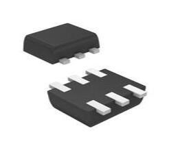
Surface Mount - Package / Case
refers to the protective housing that encases an electronic component, providing mechanical support, electrical connections, and thermal management.
32-WFQFN Exposed Pad - Number of Pins32
- Operating Temperature
The operating temperature is the range of ambient temperature within which a power supply, or any other electrical equipment, operate in. This ranges from a minimum operating temperature, to a peak or maximum operating temperature, outside which, the power supply may fail.
-40°C~125°C TJ - Packaging
Semiconductor package is a carrier / shell used to contain and cover one or more semiconductor components or integrated circuits. The material of the shell can be metal, plastic, glass or ceramic.
Tape & Reel (TR) - Published2016
- Part Status
Parts can have many statuses as they progress through the configuration, analysis, review, and approval stages.
Active - Moisture Sensitivity Level (MSL)
Moisture Sensitivity Level (MSL) is a standardized rating that indicates the susceptibility of electronic components, particularly semiconductors, to moisture-induced damage during storage and the soldering process, defining the allowable exposure time to ambient conditions before they require special handling or baking to prevent failures
1 (Unlimited) - Base Part Number
The "Base Part Number" (BPN) in electronic components serves a similar purpose to the "Base Product Number." It refers to the primary identifier for a component that captures the essential characteristics shared by a group of similar components. The BPN provides a fundamental way to reference a family or series of components without specifying all the variations and specific details.
LTC7813 - Function
The parameter "Function" in electronic components refers to the specific role or purpose that the component serves within an electronic circuit. It defines how the component interacts with other elements, influences the flow of electrical signals, and contributes to the overall behavior of the system. Functions can include amplification, signal processing, switching, filtering, and energy storage, among others. Understanding the function of each component is essential for designing effective and efficient electronic systems.
Step-Up, Step-Down - Number of Outputs2
- Output Type
The "Output Type" parameter in electronic components refers to the type of signal or data that is produced by the component as an output. This parameter specifies the nature of the output signal, such as analog or digital, and can also include details about the voltage levels, current levels, frequency, and other characteristics of the output signal. Understanding the output type of a component is crucial for ensuring compatibility with other components in a circuit or system, as well as for determining how the output signal can be utilized or processed further. In summary, the output type parameter provides essential information about the nature of the signal that is generated by the electronic component as its output.
Transistor Driver - Output Configuration
Output Configuration in electronic components refers to the arrangement or setup of the output pins or terminals of a device. It defines how the output signals are structured and how they interact with external circuits or devices. The output configuration can determine the functionality and compatibility of the component in a circuit design. Common types of output configurations include single-ended, differential, open-drain, and push-pull configurations, each serving different purposes and applications in electronic systems. Understanding the output configuration of a component is crucial for proper integration and operation within a circuit.
Positive - Voltage - Supply (Vcc/Vdd)
Voltage - Supply (Vcc/Vdd) is a key parameter in electronic components that specifies the voltage level required for the proper operation of the device. It represents the power supply voltage that needs to be provided to the component for it to function correctly. This parameter is crucial as supplying the component with the correct voltage ensures that it operates within its specified limits and performance characteristics. It is typically expressed in volts (V) and is an essential consideration when designing and using electronic circuits to prevent damage and ensure reliable operation.
4.5V~60V - Control Features
Control features in electronic components refer to specific functionalities or characteristics that allow users to manage and regulate the operation of the component. These features are designed to provide users with control over various aspects of the component's performance, such as adjusting settings, monitoring parameters, or enabling specific modes of operation. Control features can include options for input/output configurations, power management, communication protocols, and other settings that help users customize and optimize the component's behavior according to their requirements. Overall, control features play a crucial role in enhancing the flexibility, usability, and performance of electronic components in various applications.
Enable, Frequency Control, Power Good, Soft Start, Tracking - Topology
In the context of electronic components, "topology" refers to the arrangement or configuration of the components within a circuit or system. It defines how the components are connected to each other and how signals flow between them. The choice of topology can significantly impact the performance, efficiency, and functionality of the electronic system. Common topologies include series, parallel, star, mesh, and hybrid configurations, each with its own advantages and limitations. Designers carefully select the appropriate topology based on the specific requirements of the circuit to achieve the desired performance and functionality.
Buck, Boost - Frequency - Switching
"Frequency - Switching" in electronic components refers to the rate at which a device, such as a transistor or switching regulator, turns on and off during operation. This parameter is crucial in determining the efficiency and performance of power converters, oscillators, and other circuits that rely on rapid switching. Higher switching frequencies typically allow for smaller component sizes but may require more advanced design considerations to manage heat and electromagnetic interference.
105kHz~835kHz 350kHz~535kHz - Synchronous Rectifier
Synchronous rectification is a technique for improving the efficiency of rectification by replacing diodes with actively controlled switches, usually power MOSFETs or power bipolar junction transistors (BJT).
Yes - Max Duty Cycle
Max Duty Cycle refers to the maximum percentage of time that an electronic component, such as a switch or a power supply, can be in an "on" state during a defined time period. It is an important parameter in pulse-width modulated (PWM) systems and helps determine how often a device can operate without overheating or sustaining damage. By specifying the maximum duty cycle, manufacturers provide guidance on the safe operational limits of the component, ensuring reliability and efficiency in various applications.
99 % - Duty Cycle (Max)
The "Duty Cycle (Max)" parameter in electronic components refers to the maximum percentage of time that a signal is active or on within a specific period. It is commonly used in components such as pulse-width modulation (PWM) controllers, oscillators, and timers. A duty cycle of 100% means the signal is always on, while a duty cycle of 0% means the signal is always off. Understanding the maximum duty cycle is important for ensuring proper operation and performance of the electronic component within its specified limits. It is typically expressed as a percentage and helps determine the amount of power or energy being delivered by the signal.
96%, 99% - Clock Sync
Clock synchronization is a topic in computer science and engineering that aims to coordinate otherwise independent clocks. Even when initially set accurately, real clocks will differ after some amount of time due to clock drift, caused by clocks counting time at slightly different rates.
No - Output Phases
Output Phases in electronic components refer to the number of distinct output signals or waveforms that the component can generate. This parameter is commonly associated with devices such as power inverters, motor drives, and signal generators. The output phases indicate how many separate signals can be produced simultaneously by the component, with each phase typically representing a different electrical waveform or signal. Understanding the output phases of an electronic component is important for designing and implementing systems that require multiple output signals or for ensuring compatibility with other components in a circuit.
1 - RoHS Status
RoHS means “Restriction of Certain Hazardous Substances” in the “Hazardous Substances Directive” in electrical and electronic equipment.
ROHS3 Compliant
Parts with Similar Specs
- ImagePart NumberManufacturerPackage / CaseNumber of PinsNumber of OutputsFrequency - SwitchingSynchronous RectifierRoHS StatusMounting TypeView Compare
![LTC7813EUH#TRPBF]()
LTC7813EUH#TRPBF
32-WFQFN Exposed Pad
32
2
105kHz ~ 835kHz, 350kHz ~ 535kHz
Yes
ROHS3 Compliant
Surface Mount
![UCD7242RSJT]()
32-WFQFN Exposed Pad
32
2
170kHz ~ 620kHz
Yes
ROHS3 Compliant
Surface Mount
![MAX1540AETJ]()
10-VFDFN Exposed Pad
10
2
-
Yes
ROHS3 Compliant
Surface Mount
![TPS62410DRCT]()
10-VFDFN Exposed Pad
10
2
-
Yes
ROHS3 Compliant
Surface Mount
![TPS62402DRCT]()
32-VQFN Exposed Pad
32
2
300kHz ~ 2MHz
Yes
ROHS3 Compliant
Surface Mount


Datasheet PDF
- Datasheets :
- ConflictMineralStatement :
 ATMEGA8L-8PU 8-bit Microcontrollers - MCU 8kB Flash: Datasheet, Pinout, and Package information.
21 February 20224216
 TMP100 VS TMP101
12 July 20212098
 PGA2311 Volume Control: Alternative, Package and Pinout
19 August 20214421
![EV2400 Evaluation and Demonstration Boards USB 2.0[FAQ]: Datasheet, EV2300 VS EV2400, and Features](https://res.utmel.com/Images/Article/fef602f0-bea0-4737-8ace-f64c5e9484e5.jpg) EV2400 Evaluation and Demonstration Boards USB 2.0[FAQ]: Datasheet, EV2300 VS EV2400, and Features
EV2400 Evaluation and Demonstration Boards USB 2.0[FAQ]: Datasheet, EV2300 VS EV2400, and Features28 March 20226622
 2N3055 NPN Power Transistor: Datasheet, Pinout and Specifications
17 May 202110278
 BC640 PNP Silicon Transistor: BC640, Datasheet, Equivalent
07 January 202210319
 CS124 SSR RELAY SPST-NO 3.5A 0-40V: Datasheet, Features and Equivalents
11 January 2022321
 2N7002V N-Channel MOSFET: Pinout, Datasheet and Application
09 July 2021561
 What Are Wi-Fi Modules and Their Uses in IoT Today
04 June 20252969
 Si vs SiC Diodes: A Performance Study of Interleaved Boost Converters for PV Applications
14 March 20233092
 Shenzhen: This Year Will Focus on Promoting SMIC and CR Micro 12-inch Project
13 April 20226812
 All You Need to Know about Wireless Access Point
26 October 20214759
 AC Contactor: What is Self-Locking?
01 March 202212083
 What is Brushless DC Motors (BLDC) ?
03 April 20258433
 What is a Motherboard Chipset? A Guide to 2026 Architecture
13 March 20266024
 Introduction to Flash Memory
31 October 20258794
Linear Technology/Analog Devices
In Stock: 2121
Minimum: 1 Multiples: 1
Qty
Unit Price
Ext Price
1
$11.614291
$11.61
10
$10.956878
$109.57
100
$10.336677
$1,033.67
500
$9.751582
$4,875.79
1000
$9.199606
$9,199.61
Not the price you want? Send RFQ Now and we'll contact you ASAP.
Inquire for More Quantity
![LT3845AEFE#PBF]() LT3845AEFE#PBF
LT3845AEFE#PBFLinear Technology/Analog Devices
![ADP5054ACPZ-R7]() ADP5054ACPZ-R7
ADP5054ACPZ-R7Analog Devices Inc.
![LT3748EMS#TRPBF]() LT3748EMS#TRPBF
LT3748EMS#TRPBFLinear Technology/Analog Devices
![LTC3872ETS8#TRPBF]() LTC3872ETS8#TRPBF
LTC3872ETS8#TRPBFLinear Technology/Analog Devices
![LTC3891IFE#PBF]() LTC3891IFE#PBF
LTC3891IFE#PBFLinear Technology/Analog Devices
![LTC3880EUJ#PBF]() LTC3880EUJ#PBF
LTC3880EUJ#PBFLinear Technology/Analog Devices
![LTC3789EUFD#TRPBF]() LTC3789EUFD#TRPBF
LTC3789EUFD#TRPBFLinear Technology/Analog Devices
![LTC3789EGN#TRPBF]() LTC3789EGN#TRPBF
LTC3789EGN#TRPBFLinear Technology/Analog Devices
![LTC3728EG#PBF]() LTC3728EG#PBF
LTC3728EG#PBFLinear Technology/Analog Devices
![LTC1871EMS#TRPBF]() LTC1871EMS#TRPBF
LTC1871EMS#TRPBFLinear Technology/Analog Devices


