

 Product
 Brand
 Articles
 Tools

AD623 Instrumentation Amplifier: Pinout, Circuit and Alternatives

1 Channels 17nA 90 dB Instrumentational OP Amps 0.0275μA 2.7V~12V ± 2.5V~6V AD623 8-DIP (0.300, 7.62mm)


1 Channels 17nA 90 dB Instrumentational OP Amps 0.0275μA 2.7V~12V ± 2.5V~6V AD623 8-DIP (0.300, 7.62mm)
Hello, everybody! I welcome you on board. I am glad to see you around. In this post today, I’ll walk you through the Introduction to AD623. AD623 is a single and dual supply, rail-to-rail, low cost instrumentation amplifier. I suggest you buckle up since I’ll introduce the complete Introduction to AD623 featuring pinout, circuit, alternatives and so on. Let’s jump right in.

Increasing sensitivity. Accelerometer ADXL335 + Instrumentation Amplifier (Op Amp) AD623 + Arduino.
- What is AD623?
- How does AD623 Pinout look like?
- What' s the CAD Model of AD623?
- What's the Features of AD623?
- Specifications
- What does AD623 Functional Block Diagram look like?
- What does AD623 Simplified Block Diagram look like?
- What does AD623 Simplified Schematic look like?
- What chips can replace AD623?
- Where to use AD623?
- How to use AD623?
- Where can AD623 be applied?
- How does AD623 packaged?
- Who is the Manufacturer of AD623?
- Trend Analysis
- Datasheet PDF
What is AD623?
AD623 is an integrated, single- or dual-supply instrumentation amplifier, which delivers rail-to-rail output swing using supply voltages from 3 V to 12 V.
The AD623 offers greater user flexibility by allowing single gain set resistor programming and by conforming to the 8-lead industry standard pinout configuration.
With no external resistor, the AD623 is configured for unity single gain (G = 1), after an external resistor, the AD623 can be programmed for gains of up to 1000 times.
AD623 maintains the smallest error by increasing excellent AC common-mode rejection ratio (ACCMRR) with increasing gain. Line noise and harmonics are rejected due to CMRR up to 200HZ.
It has a wide common-mode input range and can amplify signals with a common-mode voltage as low a s 150mv below ground. It can still maintains superior performance with dual and single polarity power supplies (2.5 to 6V).
Low power consumption, wide power supply voltage range, and full power supply amplitude output make AD623 an ideal choice for battery power supply.
When working under low power supply voltage, the full power supply amplitude output stage maximizes the dynamic range. It can replace the discrete instrumentation amplifier design, and provides good linearity in the smallest space, and the temperature stability is very reliable.
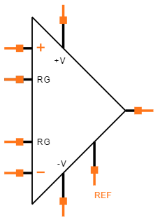
How does AD623 Pinout look like?


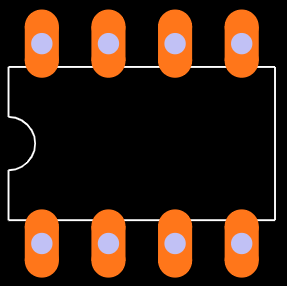
What' s the CAD Model of AD623?
Symbol
Footprint
What's the Features of AD623?
●Easy to use
●Gain range: 1 to 1000
●Rail-to-rail output swing
●Gain accuracy: 0.10% (G=1)
●800 kHz bandwidth (G = 1)
●Gain accuracy: 0.35% (G》1)
●High-precision DC performance
●Excellent dynamic specifications
●Noise: RTI noise: 35nV/√Hz (at 1kHz)
●20 µs settling time to 0.01% (G = 10)
●The gain is set by one external resistor
●Available in 8-Pin PDIP,SOIC and VSSOP packages
●Low power consumption, 550μA maximum power supply current
●The input voltage range extends 150mV below the ground voltage (single power supply)
Specifications
- TypeParameter
- Factory Lead Time8 Weeks
- Contact Plating
Contact plating (finish) provides corrosion protection for base metals and optimizes the mechanical and electrical properties of the contact interfaces.
Tin - Mount
In electronic components, the term "Mount" typically refers to the method or process of physically attaching or fixing a component onto a circuit board or other electronic device. This can involve soldering, adhesive bonding, or other techniques to secure the component in place. The mounting process is crucial for ensuring proper electrical connections and mechanical stability within the electronic system. Different components may have specific mounting requirements based on their size, shape, and function, and manufacturers provide guidelines for proper mounting procedures to ensure optimal performance and reliability of the electronic device.
Through Hole - Mounting Type
The "Mounting Type" in electronic components refers to the method used to attach or connect a component to a circuit board or other substrate, such as through-hole, surface-mount, or panel mount.
Through Hole - Package / Case
refers to the protective housing that encases an electronic component, providing mechanical support, electrical connections, and thermal management.
8-DIP (0.300, 7.62mm) - Number of Pins8
- Weight930.006106mg
- Frequency - Gain Bandwidth Product (GBP)800 kHz
- Current - Supply (Nom)375μA
- Operating Temperature
The operating temperature is the range of ambient temperature within which a power supply, or any other electrical equipment, operate in. This ranges from a minimum operating temperature, to a peak or maximum operating temperature, outside which, the power supply may fail.
-40°C~85°C - Packaging
Semiconductor package is a carrier / shell used to contain and cover one or more semiconductor components or integrated circuits. The material of the shell can be metal, plastic, glass or ceramic.
Tube - JESD-609 Code
The "JESD-609 Code" in electronic components refers to a standardized marking code that indicates the lead-free solder composition and finish of electronic components for compliance with environmental regulations.
e3 - Pbfree Code
The "Pbfree Code" parameter in electronic components refers to the code or marking used to indicate that the component is lead-free. Lead (Pb) is a toxic substance that has been widely used in electronic components for many years, but due to environmental concerns, there has been a shift towards lead-free alternatives. The Pbfree Code helps manufacturers and users easily identify components that do not contain lead, ensuring compliance with regulations and promoting environmentally friendly practices. It is important to pay attention to the Pbfree Code when selecting electronic components to ensure they meet the necessary requirements for lead-free applications.
no - Part Status
Parts can have many statuses as they progress through the configuration, analysis, review, and approval stages.
PRODUCTION (Last Updated: 3 weeks ago) - Moisture Sensitivity Level (MSL)
Moisture Sensitivity Level (MSL) is a standardized rating that indicates the susceptibility of electronic components, particularly semiconductors, to moisture-induced damage during storage and the soldering process, defining the allowable exposure time to ambient conditions before they require special handling or baking to prevent failures
1 (Unlimited) - Number of Terminations8
- Termination
Termination in electronic components refers to the practice of matching the impedance of a circuit to prevent signal reflections and ensure maximum power transfer. It involves the use of resistors or other components at the end of transmission lines or connections. Proper termination is crucial in high-frequency applications to maintain signal integrity and reduce noise.
Through Hole - ECCN Code
An ECCN (Export Control Classification Number) is an alphanumeric code used by the U.S. Bureau of Industry and Security to identify and categorize electronic components and other dual-use items that may require an export license based on their technical characteristics and potential for military use.
EAR99 - Resistance
Resistance is a fundamental property of electronic components that measures their opposition to the flow of electric current. It is denoted by the symbol "R" and is measured in ohms (Ω). Resistance is caused by the collisions of electrons with atoms in a material, which generates heat and reduces the flow of current. Components with higher resistance will impede the flow of current more than those with lower resistance. Resistance plays a crucial role in determining the behavior and functionality of electronic circuits, such as limiting current flow, voltage division, and controlling power dissipation.
2GOhm - Max Power Dissipation
The maximum power that the MOSFET can dissipate continuously under the specified thermal conditions.
650mW - Voltage - Supply
Voltage - Supply refers to the range of voltage levels that an electronic component or circuit is designed to operate with. It indicates the minimum and maximum supply voltage that can be applied for the device to function properly. Providing supply voltages outside this range can lead to malfunction, damage, or reduced performance. This parameter is critical for ensuring compatibility between different components in a circuit.
9V - Terminal Position
In electronic components, the term "Terminal Position" refers to the physical location of the connection points on the component where external electrical connections can be made. These connection points, known as terminals, are typically used to attach wires, leads, or other components to the main body of the electronic component. The terminal position is important for ensuring proper connectivity and functionality of the component within a circuit. It is often specified in technical datasheets or component specifications to help designers and engineers understand how to properly integrate the component into their circuit designs.
DUAL - Number of Functions1
- Terminal Pitch
The center distance from one pole to the next.
2.54mm - Base Part Number
The "Base Part Number" (BPN) in electronic components serves a similar purpose to the "Base Product Number." It refers to the primary identifier for a component that captures the essential characteristics shared by a group of similar components. The BPN provides a fundamental way to reference a family or series of components without specifying all the variations and specific details.
AD623 - Output Type
The "Output Type" parameter in electronic components refers to the type of signal or data that is produced by the component as an output. This parameter specifies the nature of the output signal, such as analog or digital, and can also include details about the voltage levels, current levels, frequency, and other characteristics of the output signal. Understanding the output type of a component is crucial for ensuring compatibility with other components in a circuit or system, as well as for determining how the output signal can be utilized or processed further. In summary, the output type parameter provides essential information about the nature of the signal that is generated by the electronic component as its output.
Rail-to-Rail - Power Supplies
an electronic circuit that converts the voltage of an alternating current (AC) into a direct current (DC) voltage.?
5V - Number of Channels1
- Power Dissipation
the process by which an electronic or electrical device produces heat (energy loss or waste) as an undesirable derivative of its primary action.
650mW - Current - Supply
Current - Supply is a parameter in electronic components that refers to the maximum amount of electrical current that the component can provide to the circuit it is connected to. It is typically measured in units of amperes (A) and is crucial for determining the power handling capability of the component. Understanding the current supply rating is important for ensuring that the component can safely deliver the required current without overheating or failing. It is essential to consider this parameter when designing circuits to prevent damage to the component and ensure proper functionality of the overall system.
550μA - Slew Rate
the maximum rate of output voltage change per unit time.
0.3V/μs - Amplifier Type
Amplifier Type refers to the classification or categorization of amplifiers based on their design, functionality, and characteristics. Amplifiers are electronic devices that increase the amplitude of a signal, such as voltage or current. The type of amplifier determines its specific application, performance capabilities, and operating characteristics. Common types of amplifiers include operational amplifiers (op-amps), power amplifiers, audio amplifiers, and radio frequency (RF) amplifiers. Understanding the amplifier type is crucial for selecting the right component for a particular circuit or system design.
Instrumentation - Common Mode Rejection Ratio
Common Mode Rejection Ratio (CMRR) is a measure of the ability of a differential amplifier to reject input signals that are common to both input terminals. It is defined as the ratio of the differential gain to the common mode gain. A high CMRR indicates that the amplifier can effectively eliminate noise and interference that affects both inputs simultaneously, enhancing the fidelity of the amplified signal. CMRR is typically expressed in decibels (dB), with higher values representing better performance in rejecting common mode signals.
90 dB - Current - Input Bias
The parameter "Current - Input Bias" in electronic components refers to the amount of current required at the input terminal of a device to maintain proper operation. It is a crucial specification as it determines the minimum input current needed for the component to function correctly. Input bias current can affect the performance and accuracy of the device, especially in precision applications where small signal levels are involved. It is typically specified in datasheets for operational amplifiers, transistors, and other semiconductor devices to provide users with important information for circuit design and analysis.
17nA - Voltage - Supply, Single/Dual (±)
The parameter "Voltage - Supply, Single/Dual (±)" in electronic components refers to the power supply voltage required for the proper operation of the component. This parameter indicates whether the component requires a single power supply voltage (e.g., 5V) or a dual power supply voltage (e.g., ±15V). For components that require a single power supply voltage, only one voltage level is needed for operation. On the other hand, components that require a dual power supply voltage need both positive and negative voltage levels to function correctly.Understanding the voltage supply requirements of electronic components is crucial for designing and integrating them into circuits to ensure proper functionality and prevent damage due to incorrect voltage levels.
2.7V~12V ± 2.5V~6V - Input Offset Voltage (Vos)
Input Offset Voltage (Vos) is a key parameter in electronic components, particularly in operational amplifiers. It refers to the voltage difference that must be applied between the two input terminals of the amplifier to nullify the output voltage when the input terminals are shorted together. In simpler terms, it represents the voltage required to bring the output of the amplifier to zero when there is no input signal present. Vos is an important parameter as it can introduce errors in the output signal of the amplifier, especially in precision applications where accuracy is crucial. Minimizing Vos is essential to ensure the amplifier operates with high precision and accuracy.
25μV - Bandwidth
In electronic components, "Bandwidth" refers to the range of frequencies over which the component can effectively operate or pass signals without significant loss or distortion. It is a crucial parameter for devices like amplifiers, filters, and communication systems. The bandwidth is typically defined as the difference between the upper and lower frequencies at which the component's performance meets specified criteria, such as a certain level of signal attenuation or distortion. A wider bandwidth indicates that the component can handle a broader range of frequencies, making it more versatile for various applications. Understanding the bandwidth of electronic components is essential for designing and optimizing circuits to ensure proper signal transmission and reception within the desired frequency range.
800 kHz - Neg Supply Voltage-Nom (Vsup)
The parameter "Neg Supply Voltage-Nom (Vsup)" in electronic components refers to the nominal negative supply voltage that the component requires to operate within its specified performance characteristics. This parameter indicates the minimum voltage level that must be provided to the component's negative supply pin for proper functionality. It is important to ensure that the negative supply voltage provided to the component does not exceed the maximum specified value to prevent damage or malfunction. Understanding and adhering to the specified negative supply voltage requirements is crucial for the reliable operation of the electronic component in a circuit.
-5V - Average Bias Current-Max (IIB)
The parameter "Average Bias Current-Max (IIB)" in electronic components refers to the maximum average bias current that the component can handle without exceeding its specified operating limits. Bias current is the current that flows through a component when it is in its quiescent state or when it is not actively processing a signal. Exceeding the maximum average bias current can lead to overheating, reduced performance, or even damage to the component. Therefore, it is important to ensure that the bias current does not exceed the specified maximum value to maintain the reliability and longevity of the electronic component.
0.0275μA - Power Supply Rejection Ratio (PSRR)
Power Supply Rejection Ratio (PSRR) is a measure of how well an electronic component, such as an operational amplifier or voltage regulator, can reject changes in its supply voltage. It indicates the ability of the component to maintain a stable output voltage despite fluctuations in the input supply voltage. A higher PSRR value signifies better performance in rejecting noise and variations from the power supply, leading to improved signal integrity and more reliable operation in electronic circuits. PSRR is typically expressed in decibels (dB).
80dB - Supply Voltage Limit-Max
The parameter "Supply Voltage Limit-Max" in electronic components refers to the maximum voltage that the component can safely handle without getting damaged. This specification is crucial for ensuring the reliable operation and longevity of the component within a given electrical system. Exceeding the maximum supply voltage limit can lead to overheating, electrical breakdown, or permanent damage to the component. It is important to carefully adhere to this limit when designing and operating electronic circuits to prevent potential failures and ensure the overall system's performance and safety.
6V - -3db Bandwidth
The "-3dB bandwidth" of an electronic component refers to the frequency range over which the component's output signal power is reduced by 3 decibels (dB) compared to its maximum output power. This parameter is commonly used to describe the frequency response of components such as amplifiers, filters, and other signal processing devices. The -3dB point is significant because it represents the half-power point, where the output signal power is reduced to half of its maximum value. Understanding the -3dB bandwidth is important for designing and analyzing electronic circuits to ensure that signals are accurately processed within the desired frequency range.
0.8MHz - Dual Supply Voltage
Dual Supply Voltage refers to an electronic component's requirement for two separate power supply voltages, typically one positive and one negative. This configuration is commonly used in operational amplifiers, analog circuits, and certain digital devices to allow for greater signal handling capabilities and improved performance. The use of dual supply voltages enables the device to process bipolar signals, thereby enhancing its functionality in various applications.
5V - Input Offset Current-Max (IIO)
Input Offset Current-Max (IIO) is a parameter that describes the maximum difference in input bias currents between two input terminals of an electronic component, such as an operational amplifier. Input offset current can cause errors in the output of the component, especially in precision applications where accuracy is crucial. The IIO specification provides a limit on the maximum allowable difference in input currents to ensure that the component operates within its specified performance range. Designers need to consider the IIO value when selecting components and designing circuits to minimize errors and ensure reliable operation.
0.0025μA - Voltage Gain-Min
Voltage Gain-Min is a parameter used to describe the minimum amplification factor of an electronic component, such as an amplifier or transistor. It represents the smallest amount by which the input voltage signal is amplified to produce the output voltage signal. A higher Voltage Gain-Min value indicates a greater amplification capability of the component. This parameter is crucial in determining the performance and efficiency of electronic circuits, as it directly influences the signal strength and quality of the output. Manufacturers provide this specification to help engineers and designers select the appropriate components for their specific application requirements.
1 - Height3.43mm
- Length9.27mm
- Width7.24mm
- REACH SVHC
The parameter "REACH SVHC" in electronic components refers to the compliance with the Registration, Evaluation, Authorization, and Restriction of Chemicals (REACH) regulation regarding Substances of Very High Concern (SVHC). SVHCs are substances that may have serious effects on human health or the environment, and their use is regulated under REACH to ensure their safe handling and minimize their impact.Manufacturers of electronic components need to declare if their products contain any SVHCs above a certain threshold concentration and provide information on the safe use of these substances. This information allows customers to make informed decisions about the potential risks associated with using the components and take appropriate measures to mitigate any hazards.Ensuring compliance with REACH SVHC requirements is essential for electronics manufacturers to meet regulatory standards, protect human health and the environment, and maintain transparency in their supply chain. It also demonstrates a commitment to sustainability and responsible manufacturing practices in the electronics industry.
No SVHC - Radiation Hardening
Radiation hardening is the process of making electronic components and circuits resistant to damage or malfunction caused by high levels of ionizing radiation, especially for environments in outer space (especially beyond the low Earth orbit), around nuclear reactors and particle accelerators, or during nuclear accidents or nuclear warfare.
No - RoHS Status
RoHS means “Restriction of Certain Hazardous Substances” in the “Hazardous Substances Directive” in electrical and electronic equipment.
ROHS3 Compliant - Lead Free
Lead Free is a term used to describe electronic components that do not contain lead as part of their composition. Lead is a toxic material that can have harmful effects on human health and the environment, so the electronics industry has been moving towards lead-free components to reduce these risks. Lead-free components are typically made using alternative materials such as silver, copper, and tin. Manufacturers must comply with regulations such as the Restriction of Hazardous Substances (RoHS) directive to ensure that their products are lead-free and environmentally friendly.
Contains Lead
What does AD623 Functional Block Diagram look like?

What does AD623 Simplified Block Diagram look like?

What does AD623 Simplified Schematic look like?

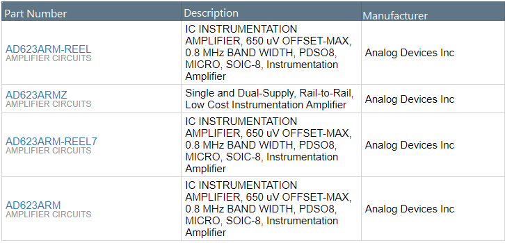
What chips can replace AD623?
Where to use AD623?
The AD623 is an Instrumentation Amplifier with rail-to-rail feature. It also operates at a very low current of 550nA making it suitable for battery operated applications.
Instrumentation amplifier: Instrumentation amplifier is a type of differential amplifier that has buffer amplifiers connected to their input pins. This eliminates the need for impedance matching, thus making it practically suitable for measurement and test equipments.
Rail-to-rail Op-Amp: The output pin of a normal op-amp will not be able to provide voltage that is equal to the supply voltage. This is because of the output stage transistors which prevent the amplifier from reaching the maximum positive voltage or minimum negative voltage. Rail-to-rail op-Amp overcomes this problem and hence the output pin can reach either positive rail voltage or negative rail voltage.
How to use AD623?
The AD623 only requires a resistor to sets its gain value and hence can be easily set up. A very basic commonly used circuit for AD623 is shown below.

The IC is powered using the pin 7 and pin 4, here I have used a singly supply of +5V hence the pin 4 is grounded. If a dual supply voltage is used the pin 4 will be provided with negative voltage. The non - inverting pin (pin 2) and the inverting pin (pin 3) is connected the signal which has to be amplified or compared base on the application of the Op-Amp. The Reference pin (pin 5) is normally grounded along with pin 4, the reference pin is used to direct the output towards a voltage when the difference voltage between the inverting and the non-inverting pin is 0V.
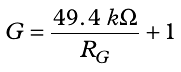
The gain of an op-amp can be set by simply connecting the right value of resistor across the pin +Rg (pin 8) and the pin –Rg (pin 1). Here I have connected a resistor of value 500Ω which will set the op-amp at a gain value of 100. The formulae to calculate the value of gain from R is given below
Alternatively you can also use the chart below which has the value of resistor and standard gain values listed.

Where can AD623 be applied?
●Difference amplifiers
●Transducer interfaces
●Thermocouple amplifiers
●Industrial process control
●Power sensitive applications
●Calibration and test equipments
●Low power medical instrumentation
●Low power data acquisition devices
How does AD623 packaged?

Who is the Manufacturer of AD623?
ADI (NASDAQ: ADI) is the world leader in the design, manufacture and marketing of a broad portfolio of high-performance analog, mixed-signal, and digital signal processing (DSP) integrated circuits (IC) electronic devices. Since our establishment in 1965, we have been focusing on solving engineering challenges related to signal processing in electronic equipment. Our signal processing products are used by more than 100,000 customers around the world, and play an important role in converting, regulating and processing real-world phenomena such as temperature, pressure, sound, light, speed and motion into electrical signals for use in a wide array of Electronic equipment.
Trend Analysis
Datasheet PDF
- Datasheets :
- PCN Design/Specification :
- ConflictMineralStatement :
1.How does AD623 output full voltage?
AD623 is a differential op amp for precision instruments. The input and output are rail-to-rail.

The internally set feedback resistance of 24.9k ohms. We only need to adjust RG to achieve the specified magnification.

The maximum input voltage value of RG, a reasonable setting of RG can completely achieve full voltage output.
2.What is the role of AD623 REF?
REF is the reference terminal, which is the output voltage whose potential is defined as zero, which is particularly useful.

When the load is not shared precisely with the rest of the system, it provides a direct means to inject an accurate offset output.

It is also very useful to amplify bipolar signals because it can be used to provide a virtual ground voltage as a reference terminal.

The voltage on the reference terminal can range from -Vs to +Vs.
3.Why is the output of AD623 a sine wave when inputting a square wave?
The input frequency is too high, the amplifier bandwidth is too narrow, the higher harmonics are attenuated, and it looks like a sine wave.
4.What is the highest signal input frequency of AD623?
AD623 does not have an upper limit of the input frequency.

Its unity gain bandwidth is 800kHz (typical value).

When the input sine wave signal reaches this frequency, its voltage gain is 1, that is, it loses its amplification effect, and nothing more.
5.When using AD623, can we amplify mV-level AC signals, single power supply?
The typical offset voltage of AD623 is only 25μV, so it is possible to amplify mV-level AC signals, but its bandwidth is not very large.

When the gain is 10 times, the bandwidth is only 100kHz. When the gain is 100 times, the bandwidth is only 10kHz.

Note that the frequency of the AC signal should not be too high, it is no problem.
6.What is the operating voltage of the dual power supply of AD623?
The dual power supply voltage range of AD623 is ±2.5V-6V.
 The Review of W5500 Hardwired TCP IP Embedded Ethernet Controller
14 April 202210804
 MJE340 Transistor:Pinout, Equivalent, Datasheet
04 December 20219342
 AMD Kintex-7 XC7K480T FPGA: Technical Analysis and Design Guide
14 January 20261634
 The Comprehensive Introductions to LMD18200T
14 November 20222958
 SG3524N IC REG CTRLR MULT TOPOLOGY 16DIP: Datasheet, Circuit, Pinout and Equivalents
16 February 202211727
 LTC4260 Hot Swap Controller: Pinout, Datasheet and Schematics
14 September 20212078
 LM2902N Low-power quad operational amplifier:Pinout, Features, and Datasheet
13 September 20212949
 SST25VF020 2 Mbit SPI Serial Flash: Pinout, Equivalent and Datasheet
24 March 20221037
 Review of Flux-Concentrated Transverse Flux Permanent Magnet Machines
15 December 20232512
 How Does the A4988 Stepper Motor Driver Work
29 August 20267410
 Schottky Diodes: Principle, Functions, and Applications
21 October 202527596
 Three-Level Integration of Circuits
05 May 20224240
 What Is a MOSFET? Working Principle, Types, and Selection Guide
15 July 20268517
 Everything You Need to Know about RF Chip
14 January 202621797
 What is FPC (Flexible Printed Circuit)?
26 December 202516676
 Hot Swap Controllers:Semiconductors That Provide In-circuit Protection and Control Functions
22 February 20235059
Analog Devices Inc.
In Stock: 2350
United States
China
Canada
Japan
Russia
Germany
United Kingdom
Singapore
Italy
Hong Kong(China)
Taiwan(China)
France
Korea
Mexico
Netherlands
Malaysia
Austria
Spain
Switzerland
Poland
Thailand
Vietnam
India
United Arab Emirates
Afghanistan
Åland Islands
Albania
Algeria
American Samoa
Andorra
Angola
Anguilla
Antigua & Barbuda
Argentina
Armenia
Aruba
Australia
Azerbaijan
Bahamas
Bahrain
Bangladesh
Barbados
Belarus
Belgium
Belize
Benin
Bermuda
Bhutan
Bolivia
Bonaire, Sint Eustatius and Saba
Bosnia & Herzegovina
Botswana
Brazil
British Indian Ocean Territory
British Virgin Islands
Brunei
Bulgaria
Burkina Faso
Burundi
Cabo Verde
Cambodia
Cameroon
Cayman Islands
Central African Republic
Chad
Chile
Christmas Island
Cocos (Keeling) Islands
Colombia
Comoros
Congo
Congo (DRC)
Cook Islands
Costa Rica
Côte d’Ivoire
Croatia
Cuba
Curaçao
Cyprus
Czechia
Denmark
Djibouti
Dominica
Dominican Republic
Ecuador
Egypt
El Salvador
Equatorial Guinea
Eritrea
Estonia
Eswatini
Ethiopia
Falkland Islands
Faroe Islands
Fiji
Finland
French Guiana
French Polynesia
Gabon
Gambia
Georgia
Ghana
Gibraltar
Greece
Greenland
Grenada
Guadeloupe
Guam
Guatemala
Guernsey
Guinea
Guinea-Bissau
Guyana
Haiti
Honduras
Hungary
Iceland
Indonesia
Iran
Iraq
Ireland
Isle of Man
Israel
Jamaica
Jersey
Jordan
Kazakhstan
Kenya
Kiribati
Kosovo
Kuwait
Kyrgyzstan
Laos
Latvia
Lebanon
Lesotho
Liberia
Libya
Liechtenstein
Lithuania
Luxembourg
Macao(China)
Madagascar
Malawi
Maldives
Mali
Malta
Marshall Islands
Martinique
Mauritania
Mauritius
Mayotte
Micronesia
Moldova
Monaco
Mongolia
Montenegro
Montserrat
Morocco
Mozambique
Myanmar
Namibia
Nauru
Nepal
New Caledonia
New Zealand
Nicaragua
Niger
Nigeria
Niue
Norfolk Island
North Korea
North Macedonia
Northern Mariana Islands
Norway
Oman
Pakistan
Palau
Palestinian Authority
Panama
Papua New Guinea
Paraguay
Peru
Philippines
Pitcairn Islands
Portugal
Puerto Rico
Qatar
Réunion
Romania
Rwanda
Samoa
San Marino
São Tomé & Príncipe
Saudi Arabia
Senegal
Serbia
Seychelles
Sierra Leone
Sint Maarten
Slovakia
Slovenia
Solomon Islands
Somalia
South Africa
South Sudan
Sri Lanka
St Helena, Ascension, Tristan da Cunha
St. Barthélemy
St. Kitts & Nevis
St. Lucia
St. Martin
St. Pierre & Miquelon
St. Vincent & Grenadines
Sudan
Suriname
Svalbard & Jan Mayen
Sweden
Syria
Tajikistan
Tanzania
Timor-Leste
Togo
Tokelau
Tonga
Trinidad & Tobago
Tunisia
Turkey
Turkmenistan
Turks & Caicos Islands
Tuvalu
U.S. Outlying Islands
U.S. Virgin Islands
Uganda
Ukraine
Uruguay
Uzbekistan
Vanuatu
Vatican City
Venezuela
Wallis & Futuna
Yemen
Zambia
Zimbabwe
![AD826AR-REEL7]() AD826AR-REEL7
Analog Devices Inc.
![AD8062ARM]() AD8062ARM
Analog Devices Inc.
![AD8532ARU-REEL]() AD8532ARU-REEL
Analog Devices Inc.
![OP113ES]() OP113ES
Analog Devices Inc.
![SSM2142P]() SSM2142P
Analog Devices, Inc.
![LTC1050CS8]() LTC1050CS8
Linear Technology/Analog Devices
![AMP02EPZ]() AMP02EPZ
Analog Devices Inc.
![AD822ARZ-REEL7]() AD822ARZ-REEL7
Analog Devices Inc.
![OP2177ARZ-REEL7]() OP2177ARZ-REEL7
Analog Devices Inc.
![AD8066ARZ-R7]() AD8066ARZ-R7
Analog Devices Inc.


