FT10001 Reset Timer: Datasheet, Pinout, Circuit
6 Terminals FT10001 Voltage supervisor Min 1.8V Max 5V
Unit Price: $0.595175
Ext Price: $0.60


6 Terminals FT10001 Voltage supervisor Min 1.8V Max 5V
The FT10001 is a timer for resetting a mobile device where long reset times are needed. This article mainly covers its datasheet, pinout, circuit and more detailed information about FT10001
FT10001 Description
The FT10001 is a timer for resetting a mobile device where long reset times are needed. The long delay helps avoid unintended resets caused by accidental key presses. It has one input for single-button resetting capability. The device has a single open-drain output with 0.5mA pull-down drive.
FT10001 Pinout
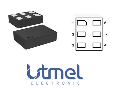

FT10001 Features
Fixed Reset Delay:10 seconds
One Input Reset pin
Open-Drain Output Pin with Fixed 530ms Pulse
1.8V to 5.0V Operation
1.7V to 5.0V Operation
1.65V to 5.00V Operation
Zero-Second Test-Mode Enable
Integrated Pull-up Resistor on/ SRO
FT10001 Block Diagram
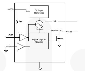
Specifications
- TypeParameter
- Factory Lead Time7 Weeks
- Lifecycle Status
Lifecycle Status refers to the current stage of an electronic component in its product life cycle, indicating whether it is active, obsolete, or transitioning between these states. An active status means the component is in production and available for purchase. An obsolete status indicates that the component is no longer being manufactured or supported, and manufacturers typically provide a limited time frame for support. Understanding the lifecycle status is crucial for design engineers to ensure continuity and reliability in their projects.
ACTIVE (Last Updated: 4 days ago) - Mount
In electronic components, the term "Mount" typically refers to the method or process of physically attaching or fixing a component onto a circuit board or other electronic device. This can involve soldering, adhesive bonding, or other techniques to secure the component in place. The mounting process is crucial for ensuring proper electrical connections and mechanical stability within the electronic system. Different components may have specific mounting requirements based on their size, shape, and function, and manufacturers provide guidelines for proper mounting procedures to ensure optimal performance and reliability of the electronic device.
Surface Mount - Mounting Type
The "Mounting Type" in electronic components refers to the method used to attach or connect a component to a circuit board or other substrate, such as through-hole, surface-mount, or panel mount.
Surface Mount - Package / Case
refers to the protective housing that encases an electronic component, providing mechanical support, electrical connections, and thermal management.
6-UFDFN - Number of Pins6
- Weight30g
- Packaging
Semiconductor package is a carrier / shell used to contain and cover one or more semiconductor components or integrated circuits. The material of the shell can be metal, plastic, glass or ceramic.
Tape & Reel (TR) - Published2016
- Operating Temperature
The operating temperature is the range of ambient temperature within which a power supply, or any other electrical equipment, operate in. This ranges from a minimum operating temperature, to a peak or maximum operating temperature, outside which, the power supply may fail.
-40°C~85°C TA - JESD-609 Code
The "JESD-609 Code" in electronic components refers to a standardized marking code that indicates the lead-free solder composition and finish of electronic components for compliance with environmental regulations.
e4 - Pbfree Code
The "Pbfree Code" parameter in electronic components refers to the code or marking used to indicate that the component is lead-free. Lead (Pb) is a toxic substance that has been widely used in electronic components for many years, but due to environmental concerns, there has been a shift towards lead-free alternatives. The Pbfree Code helps manufacturers and users easily identify components that do not contain lead, ensuring compliance with regulations and promoting environmentally friendly practices. It is important to pay attention to the Pbfree Code when selecting electronic components to ensure they meet the necessary requirements for lead-free applications.
yes - Part Status
Parts can have many statuses as they progress through the configuration, analysis, review, and approval stages.
Active - Moisture Sensitivity Level (MSL)
Moisture Sensitivity Level (MSL) is a standardized rating that indicates the susceptibility of electronic components, particularly semiconductors, to moisture-induced damage during storage and the soldering process, defining the allowable exposure time to ambient conditions before they require special handling or baking to prevent failures
1 (Unlimited) - Number of Terminations6
- ECCN Code
An ECCN (Export Control Classification Number) is an alphanumeric code used by the U.S. Bureau of Industry and Security to identify and categorize electronic components and other dual-use items that may require an export license based on their technical characteristics and potential for military use.
EAR99 - TypeReset Timer
- Terminal Finish
Terminal Finish refers to the surface treatment applied to the terminals or leads of electronic components to enhance their performance and longevity. It can improve solderability, corrosion resistance, and overall reliability of the connection in electronic assemblies. Common finishes include nickel, gold, and tin, each possessing distinct properties suitable for various applications. The choice of terminal finish can significantly impact the durability and effectiveness of electronic devices.
Nickel/Gold (Ni/Au) - Max Power Dissipation
The maximum power that the MOSFET can dissipate continuously under the specified thermal conditions.
5mW - Terminal Position
In electronic components, the term "Terminal Position" refers to the physical location of the connection points on the component where external electrical connections can be made. These connection points, known as terminals, are typically used to attach wires, leads, or other components to the main body of the electronic component. The terminal position is important for ensuring proper connectivity and functionality of the component within a circuit. It is often specified in technical datasheets or component specifications to help designers and engineers understand how to properly integrate the component into their circuit designs.
DUAL - Number of Functions1
- Terminal Pitch
The center distance from one pole to the next.
0.5mm - Base Part Number
The "Base Part Number" (BPN) in electronic components serves a similar purpose to the "Base Product Number." It refers to the primary identifier for a component that captures the essential characteristics shared by a group of similar components. The BPN provides a fundamental way to reference a family or series of components without specifying all the variations and specific details.
FT10001 - Output
In electronic components, the parameter "Output" typically refers to the signal or data that is produced by the component and sent to another part of the circuit or system. The output can be in the form of voltage, current, frequency, or any other measurable quantity depending on the specific component. The output of a component is often crucial in determining its functionality and how it interacts with other components in the circuit. Understanding the output characteristics of electronic components is essential for designing and troubleshooting electronic circuits effectively.
Open Drain or Open Collector - Max Supply Voltage
In general, the absolute maximum common-mode voltage is VEE-0.3V and VCC+0.3V, but for products without a protection element at the VCC side, voltages up to the absolute maximum rated supply voltage (i.e. VEE+36V) can be supplied, regardless of supply voltage.
5V - Min Supply Voltage
The minimum supply voltage (V min ) is explored for sequential logic circuits by statistically simulating the impact of within-die process variations and gate-dielectric soft breakdown on data retention and hold time.
1.8V - Quiescent Current
The quiescent current is defined as the current level in the amplifier when it is producing an output of zero.
1μA - Reset
The "Reset" parameter in electronic components refers to a function that initializes or sets a device to a predefined state. It is often used to clear any temporary data, errors, or configurations that may have been stored during operation. The reset process can ensure that the device starts from a known good state, allowing for reliable performance in subsequent tasks. This parameter is critical in digital circuits and systems where proper initialization is necessary for correct functioning.
Active Low - Reset Timeout
The "Reset Timeout" parameter in electronic components refers to the amount of time it takes for a device to reset or return to its default state after a specific event or condition. This parameter is crucial in ensuring the proper functioning and reliability of the component, as it determines how quickly the device can recover from a fault or error situation. A shorter reset timeout typically indicates a faster response time, while a longer reset timeout may allow for more thorough error recovery processes. Designers and engineers must carefully consider the reset timeout value to meet the requirements of the application and ensure optimal performance of the electronic component.
420ms Minimum - Number of Timers/Counters1
- High Level Output Current
High-level Output Current IOH The current flowing into the output at a specified high- level voltage. Low-level Output Current IOL The current flowing into the output at a specified low- level output voltage.
-50mA - Low Level Output Current
The current into the output terminal with input conditions applied that, according to the product specification, will establish a low level at the output.
500μA - Width1mm
- Length1.45mm
- Height500μm
- Radiation Hardening
Radiation hardening is the process of making electronic components and circuits resistant to damage or malfunction caused by high levels of ionizing radiation, especially for environments in outer space (especially beyond the low Earth orbit), around nuclear reactors and particle accelerators, or during nuclear accidents or nuclear warfare.
No - RoHS Status
RoHS means “Restriction of Certain Hazardous Substances” in the “Hazardous Substances Directive” in electrical and electronic equipment.
ROHS3 Compliant
FT10001 Applications
Cell Phone
Portable Media Players
Tablets
Mobile Devices
Consumer Medical
FT10001 Circuit
FT10001 AC Test circuit and waveforms
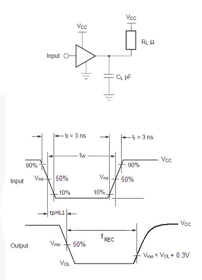
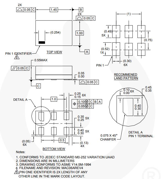
FT10001 Dimensions
FT10001 Manufacturer
ON Semiconductor (Nasdaq: ON) is driving energy efficient innovations, empowering customers to reduce global energy use, which offers a comprehensive portfolio of energy efficient power and signal management, logic, discrete and custom solutions to help design engineers solve their unique design challenges in automotive, communications, computing, consumer, industrial, LED lighting, medical, military/aerospace and power supply applications.
Datasheet PDF
- Datasheets :
- Environmental Information :
- PCN Design/Specification :
- PCN Packaging :
Popularity by Region
What is FT10001?
The FT10001 is a timer for resetting a mobile device where long reset times are needed. The long delay helps avoid unintended resets caused by accidental key presses. It has a fixed delay of 10 ±20% seconds.
What is reset timer in scratch?
The Reset Timer block is a Sensing block and a Stack block. The block sets the timer's value back to 0.0. When this block is present, the project typically utilizes the Timer output block; usually the timer must be reset at the beginning of a project for the Timer block to hold the right value.
How about FT10001 capability?
The FT10001 has one input for single-button resetting capability.
What does FT10001 have?
It has a single open-drain output with 0.5mA pull-down drive.
![SN74HC00N IC GATE NAND 4CH 2-INP 14DIP[Video]: Datasheet, Pinout, and Equivalents](https://res.utmel.com/Images/Article/6db9b92c-ecea-4b5a-9210-6814abb3eb0f.jpg) SN74HC00N IC GATE NAND 4CH 2-INP 14DIP[Video]: Datasheet, Pinout, and Equivalents
SN74HC00N IC GATE NAND 4CH 2-INP 14DIP[Video]: Datasheet, Pinout, and Equivalents12 March 20222698
 MSP430F20x1/20x2/20x3 Mixed Signal Microcontroller: Technical Insights
29 February 2024101
 LM117H Voltage Regulator: Feature, Application, and Datasheet
04 June 20211738
 LP2951 Voltage Regulator: Pinout, Equivalent and Datasheet
23 October 20212836
 FR107 Rectifier Diode: Datasheet, Features and Equivalent
24 September 202119995
 8533AG-01 LVPECL Fanout Buffer: Pinout, Features and Datasheet
28 March 2022260
 AT24CM01 Serial EEPROM: Pinout, Equivalent and Datasheet
24 December 20211464
![MPXV7002DP Integrated Silicon: Features, Pinout, and Datasheet [Video&FAQ]](https://res.utmel.com/Images/Article/763c54d7-b8f0-41c0-82d7-7ccf0be08aea.png) MPXV7002DP Integrated Silicon: Features, Pinout, and Datasheet [Video&FAQ]
MPXV7002DP Integrated Silicon: Features, Pinout, and Datasheet [Video&FAQ]13 January 20224822
 Review of IoT-Based Smart Home Security Systems- Part 1
28 March 20243443
 Types and Application of Position Sensors
31 October 20256013
 What is an Accelerometer Sensor?
20 April 202111652
 An Overview of Fiber Optic Cable
10 August 20214676
 MIT Technology Review Officially Released 2022 Top 10 Breakthrough Technologies in the World
26 April 20224695
 Introduction to FinFET
18 March 202125808
 Global Power Technology Authorized Distributor | UTMEL Electronics
21 November 20232436
 What is Transceiver?
30 September 20211939
ON Semiconductor
In Stock: 16
Minimum: 1 Multiples: 1
Qty
Unit Price
Ext Price
1
$0.595175
$0.60
10
$0.561486
$5.61
100
$0.529704
$52.97
500
$0.499721
$249.86
1000
$0.471435
$471.44
Not the price you want? Send RFQ Now and we'll contact you ASAP.
Inquire for More Quantity


