
 Product
 Brand
Brand Articles
 Tools
Tools
ISL80103IRAJZ Linear Regulator: Diagram, Pinout, and Datasheet

Intersil (Renesas Electronics America)
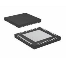
Adjustable 0.5mm PMIC 10 DFN
Unit Price: $3.196600
Ext Price: $3.20


Adjustable 0.5mm PMIC 10 DFN
The ISL80103IRAJZ is a single-output low-voltage, high-current LDO with 2A and 3A output currents, respectively. This article mainly introduces diagram, pinout, datasheet and other detailed information about Intersil (Renesas Electronics America) ISL80103IRAJZ.

Basic Linear Regulator Operation
- ISL80103IRAJZ Description
- ISL80103IRAJZ Pinout
- ISL80103IRAJZ CAD Model
- ISL80103IRAJZ Features
- Specifications
- ISL80103IRAJZ Functional Block Diagram
- ISL80103IRAJZ Typical Application
- ISL80103IRAJZ Alternatives
- ISL80103IRAJZ Applications
- ISL80103IRAJZ Package
- ISL80103IRAJZ Manufacturer
- Trend Analysis
- Datasheet PDF
ISL80103IRAJZ Description
The ISL80103IRAJZ is a single-output low-voltage, high-current LDO with 2A and 3A output currents, respectively. These LDOs have an input voltage range of 2.2V to 6V and can provide output voltages ranging from 0.8V to 5V on the adjustable VOUT variants. Fixed output voltages of 1.8V, 2.5V, 3.3V, and 5V are available. On request, more unique voltage options are available.
An external capacitor on the soft-start pin provides adjustability for applications that require in-rush current less than the current limit. The ENABLE function enables the part to enter a low quiescent current shutdown mode. This product series uses a sub-micron BiCMOS technology to give best-in-class analog performance and total value.
In comparison to bipolar LDOs, this CMOS (LDOs) will consume much less quiescent current as a function of load, resulting in improved efficiency and the potential to explore packages with smaller footprints. To enable a leading class fast load transient response and hence a shorter overall AC regulation band for an LDO in this category, the quiescent current has been modestly reduced.
ISL80103IRAJZ Pinout
The ISL80103IRAJZ Pinout is shown as follows.

Pinout
| Pin Number | Pin Name | Description |
| 1, 2 | VOUT | Output voltage pin. |
| 3 | SENSE/ADJ | Remote voltage sense for internally fixed VOUT options. ADJ pin for externally set VOUT. |
| 4 | PG | VOUT in the regulation signal. Logic low defines when VOUT is not in regulation. Must be grounded if not used. |
| 5 | GND | GND pin. |
| 6 | SS | External cap adjusts in-rush current. |
| 7 | ENABLE | VIN independent chip enable. TTL and CMOS compatible. |
| 8 | DNC | Do not connect this pin to ground or supply. Leave floating |
| 9, 10 | VIN | Input supply pin. |
| EPAD | EPAD must be connected to copper plane with as many vias as possible for proper electrical and optimal thermal performance. |
ISL80103IRAJZ CAD Model
The following figure is ISL80103IRAJZ Symbol and Footprint.

Symbol

Footprint
ISL80103IRAJZ Features
• Stable with all capacitor types
• 2A and 3A output current ratings
• 2.2V to 6V input voltage range
• ±1.8% VOUT accuracy guaranteed over line, load and TJ = -40°C to +125°C
• Very low 120mV dropout voltage at 3A
• Fixed and adjustable VOUT versions
• Very fast transient response
• Excellent 62dB PSRR
• 100µVRMS output noise
• Power-good output
• Adjustable in-rush current limiting
• Short circuit and over-temperature protection
• Available in a 10 Ld DFN
• Servers
• Telecommunications and networking
• Medical equipment
• Instrumentation systems
• Routers and switchers
Specifications
- TypeParameter
- Factory Lead Time8 Weeks
- Mount
In electronic components, the term "Mount" typically refers to the method or process of physically attaching or fixing a component onto a circuit board or other electronic device. This can involve soldering, adhesive bonding, or other techniques to secure the component in place. The mounting process is crucial for ensuring proper electrical connections and mechanical stability within the electronic system. Different components may have specific mounting requirements based on their size, shape, and function, and manufacturers provide guidelines for proper mounting procedures to ensure optimal performance and reliability of the electronic device.
Surface Mount - Package / Case
refers to the protective housing that encases an electronic component, providing mechanical support, electrical connections, and thermal management.
DFN - Number of Pins10
- Published2008
- JESD-609 Code
The "JESD-609 Code" in electronic components refers to a standardized marking code that indicates the lead-free solder composition and finish of electronic components for compliance with environmental regulations.
e3 - Part Status
Parts can have many statuses as they progress through the configuration, analysis, review, and approval stages.
Active - Moisture Sensitivity Level (MSL)
Moisture Sensitivity Level (MSL) is a standardized rating that indicates the susceptibility of electronic components, particularly semiconductors, to moisture-induced damage during storage and the soldering process, defining the allowable exposure time to ambient conditions before they require special handling or baking to prevent failures
3 (168 Hours) - Number of Terminations10
- ECCN Code
An ECCN (Export Control Classification Number) is an alphanumeric code used by the U.S. Bureau of Industry and Security to identify and categorize electronic components and other dual-use items that may require an export license based on their technical characteristics and potential for military use.
EAR99 - Terminal Finish
Terminal Finish refers to the surface treatment applied to the terminals or leads of electronic components to enhance their performance and longevity. It can improve solderability, corrosion resistance, and overall reliability of the connection in electronic assemblies. Common finishes include nickel, gold, and tin, each possessing distinct properties suitable for various applications. The choice of terminal finish can significantly impact the durability and effectiveness of electronic devices.
Matte Tin (Sn) - annealed - Max Operating Temperature
The Maximum Operating Temperature is the maximum body temperature at which the thermistor is designed to operate for extended periods of time with acceptable stability of its electrical characteristics.
125°C - Min Operating Temperature
The "Min Operating Temperature" parameter in electronic components refers to the lowest temperature at which the component is designed to operate effectively and reliably. This parameter is crucial for ensuring the proper functioning and longevity of the component, as operating below this temperature may lead to performance issues or even damage. Manufacturers specify the minimum operating temperature to provide guidance to users on the environmental conditions in which the component can safely operate. It is important to adhere to this parameter to prevent malfunctions and ensure the overall reliability of the electronic system.
-40°C - Terminal Position
In electronic components, the term "Terminal Position" refers to the physical location of the connection points on the component where external electrical connections can be made. These connection points, known as terminals, are typically used to attach wires, leads, or other components to the main body of the electronic component. The terminal position is important for ensuring proper connectivity and functionality of the component within a circuit. It is often specified in technical datasheets or component specifications to help designers and engineers understand how to properly integrate the component into their circuit designs.
DUAL - Terminal Form
Occurring at or forming the end of a series, succession, or the like; closing; concluding.
NO LEAD - Peak Reflow Temperature (Cel)
Peak Reflow Temperature (Cel) is a parameter that specifies the maximum temperature at which an electronic component can be exposed during the reflow soldering process. Reflow soldering is a common method used to attach electronic components to a circuit board. The Peak Reflow Temperature is crucial because it ensures that the component is not damaged or degraded during the soldering process. Exceeding the specified Peak Reflow Temperature can lead to issues such as component failure, reduced performance, or even permanent damage to the component. It is important for manufacturers and assemblers to adhere to the recommended Peak Reflow Temperature to ensure the reliability and functionality of the electronic components.
260 - Number of Functions1
- Terminal Pitch
The center distance from one pole to the next.
0.5mm - Time@Peak Reflow Temperature-Max (s)
Time@Peak Reflow Temperature-Max (s) refers to the maximum duration that an electronic component can be exposed to the peak reflow temperature during the soldering process, which is crucial for ensuring reliable solder joint formation without damaging the component.
30 - Pin Count
a count of all of the component leads (or pins)
10 - Number of Outputs1
- Qualification Status
An indicator of formal certification of qualifications.
Not Qualified - Output Type
The "Output Type" parameter in electronic components refers to the type of signal or data that is produced by the component as an output. This parameter specifies the nature of the output signal, such as analog or digital, and can also include details about the voltage levels, current levels, frequency, and other characteristics of the output signal. Understanding the output type of a component is crucial for ensuring compatibility with other components in a circuit or system, as well as for determining how the output signal can be utilized or processed further. In summary, the output type parameter provides essential information about the nature of the signal that is generated by the electronic component as its output.
Adjustable - Max Output Current
The maximum current that can be supplied to the load.
3A - Polarity
In electronic components, polarity refers to the orientation or direction in which the component must be connected in a circuit to function properly. Components such as diodes, capacitors, and LEDs have polarity markings to indicate which terminal should be connected to the positive or negative side of the circuit. Connecting a component with incorrect polarity can lead to malfunction or damage. It is important to pay attention to polarity markings and follow the manufacturer's instructions to ensure proper operation of electronic components.
Positive - Max Output Voltage
The maximum output voltage refers to the dynamic area beyond which the output is saturated in the positive or negative direction, and is limited according to the load resistance value.
5V - Voltage - Output
Voltage - Output is a parameter that refers to the electrical potential difference between the output terminal or pin of an electronic component and a reference point, typically ground. It indicates the level of voltage that the component is capable of providing at its output under specified operating conditions. This parameter is crucial in determining the performance and functionality of the component in a circuit, as it directly affects the signal or power being delivered to other components or devices connected to the output. Engineers and designers use the voltage output specification to ensure compatibility and proper functioning of the component within the overall system.
5V - Min Input Voltage
The parameter "Min Input Voltage" in electronic components refers to the minimum voltage level that must be applied to the component for it to operate within its specified parameters. This value is crucial as providing a voltage below this minimum threshold may result in the component malfunctioning or not functioning at all. It is important to adhere to the specified minimum input voltage to ensure the proper operation and longevity of the electronic component. Failure to meet this requirement may lead to potential damage to the component or the overall system in which it is used.
2.2V - Max Input Voltage
Max Input Voltage refers to the maximum voltage level that an electronic component can safely handle without getting damaged. This parameter is crucial for ensuring the proper functioning and longevity of the component. Exceeding the specified maximum input voltage can lead to overheating, electrical breakdown, or permanent damage to the component. It is important to carefully adhere to the manufacturer's guidelines regarding the maximum input voltage to prevent any potential issues and maintain the reliability of the electronic device.
6V - Dropout Voltage
Dropout voltage is the input-to-output differential voltage at which the circuit ceases to regulate against further reductions in input voltage; this point occurs when the input voltage approaches the output voltage.
120mV - Min Output Voltage
Min Output Voltage refers to the lowest voltage level that an electronic component, such as a voltage regulator or power supply, can provide reliably under specified conditions. It indicates the minimum threshold required for proper operation of connected devices. Operating below this voltage may lead to device malfunction or failure to operate as intended.
800mV - Power Supply Rejection Ratio (PSRR)
Power Supply Rejection Ratio (PSRR) is a measure of how well an electronic component, such as an operational amplifier or voltage regulator, can reject changes in its supply voltage. It indicates the ability of the component to maintain a stable output voltage despite fluctuations in the input supply voltage. A higher PSRR value signifies better performance in rejecting noise and variations from the power supply, leading to improved signal integrity and more reliable operation in electronic circuits. PSRR is typically expressed in decibels (dB).
62dB - Length3mm
- Width3mm
- REACH SVHC
The parameter "REACH SVHC" in electronic components refers to the compliance with the Registration, Evaluation, Authorization, and Restriction of Chemicals (REACH) regulation regarding Substances of Very High Concern (SVHC). SVHCs are substances that may have serious effects on human health or the environment, and their use is regulated under REACH to ensure their safe handling and minimize their impact.Manufacturers of electronic components need to declare if their products contain any SVHCs above a certain threshold concentration and provide information on the safe use of these substances. This information allows customers to make informed decisions about the potential risks associated with using the components and take appropriate measures to mitigate any hazards.Ensuring compliance with REACH SVHC requirements is essential for electronics manufacturers to meet regulatory standards, protect human health and the environment, and maintain transparency in their supply chain. It also demonstrates a commitment to sustainability and responsible manufacturing practices in the electronics industry.
No SVHC - RoHS Status
RoHS means “Restriction of Certain Hazardous Substances” in the “Hazardous Substances Directive” in electrical and electronic equipment.
RoHS Compliant - Lead Free
Lead Free is a term used to describe electronic components that do not contain lead as part of their composition. Lead is a toxic material that can have harmful effects on human health and the environment, so the electronics industry has been moving towards lead-free components to reduce these risks. Lead-free components are typically made using alternative materials such as silver, copper, and tin. Manufacturers must comply with regulations such as the Restriction of Hazardous Substances (RoHS) directive to ensure that their products are lead-free and environmentally friendly.
Lead Free
ISL80103IRAJZ Functional Block Diagram
The following figure is ISL80103IRAJZ Functional Block Diagram.

Functional Block Diagram
ISL80103IRAJZ Typical Application
The following figure is ISL80103IRAJZ Typical Application.

Typical Application
ISL80103IRAJZ Alternatives
| Part Number | Description | Manufacturer |
| ISL80103IRAJZ-TPOWER CIRCUITS | High Performance 3A Linear Regulator; DFN10; Temp Range: -40° to 125°C | Intersil Corporation |
ISL80103IRAJZ Applications
• Servers
• Telecommunications and Networking
• Medical Equipment
• Instrumentation Systems
• Routers and Switchers
ISL80103IRAJZ Package
The ISL80103IRAJZ Package is shown as follows.

Package
ISL80103IRAJZ Manufacturer
Renesas and Intersil will merge on January 1, 2018, resulting in a considerable increase in semiconductor inherent capabilities. Intersil's market-leading expertise in high-performance power management and precision analog devices is combined with Renesas' globally regarded MCU and SoC technologies. As a result, organic expansion in the automotive, industrial, and broad-based industries occurs, allowing the new company to respond more quickly to clients' system requirements.
The merger of Renesas and Intersil began on February 24, 2017, with the completion of the acquisition, and the unified "One Global Renesas" went into operation across all markets the following July, bringing together the strengths of both companies in anticipation of customer needs in a rapidly changing market environment. This genuinely worldwide company has a tremendous amount of synergy. Join Renesas as it improves its position as the world's premier semiconductor manufacturer.
Trend Analysis
Datasheet PDF
- Datasheets :
How do linear regulators work?
A linear regulator operates by using a voltage-controlled current source to force a fixed voltage to appear at the regulator output terminal (see Figure 1). ... The design limit of the current source defines the maximum load current the regulator can source and still maintain regulation.
Where are linear regulators used?
The use of a linear regulator at the front-end of components that need a steady voltage or are susceptible to noise will enable constant and safe operation at a steady voltage.
What is the difference between linear and switching regulators?
Switching regulators are able to generate output voltages that are higher than the input voltage or of opposite polarity, unlike linear regulators. The versatility of these converters allows configuration for the buck, boost, buck-boost, flyback, inverting in isolated and non-isolated applications.
What is a single-output low-voltage?
ISL80103IRAJZ.
What is the input voltage range of the ISL80103IRAJZ?
2.2V to 6V.
What type of voltage options are available on request?
Unique voltage options.
What function allows the part to enter a low quiescent current shutdown mode?
ENABLE.
What technology does the ENABLE function use to give best-in-class analog performance and total value?
BiCMOS technology.
What does the ISL80103IRAJZ stand for?
CMOS (LDOs).
What has been done to enable a leading class fast load transient response?
The quiescent current has been modestly reduced.
 AMD Xilinx XC95108F-20PQG160I CPLD Overview
20 May 2025213
 MCP2200 Converter: Features, Pinout, and Datasheet
24 November 20212424
 DS17285E-3+ Real Time Clock: Pinout, Equivalent and Datasheet
17 April 2025382
 LD1117S33CTR LDO Voltage Regulator: 3.3V 950mA, LD1117S33CTR Datasheet and Circuit
12 January 20223440
 A General Introduction to TPS40140RHHT Synchronous Buck Controller
23 April 2022919
![IP2721 Powering your projects by using USB-C IP2721[Video]](https://res.utmel.com/Images/Article/d51cd0af-7e5a-4c04-9336-cc7ed73f1c88.png) IP2721 Powering your projects by using USB-C IP2721[Video]
IP2721 Powering your projects by using USB-C IP2721[Video]24 April 202211219
 LM5117 Wide Input Sync Buck with Current Monitor: Pinout and Datasheet
28 September 20223923
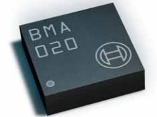 BMA020 Acceleration Sensor: Features, Specification and Datasheet
14 August 2024764
 Blackstone acquires U.S. property investment group PS Business Parks for $7.6 billion
19 May 20221276
 Active Electroacoustic Resonator-Silent Speaker
10 November 20215872
 How Nvidia Became a Chip Industry Giant
14 April 20221045
 UMD Receives $2M NSF Grant for Advancement of Semiconductor Technology and Workforce Training
27 September 20233875
 QUIC: The Next Generation Communication Protocol
22 February 20222030
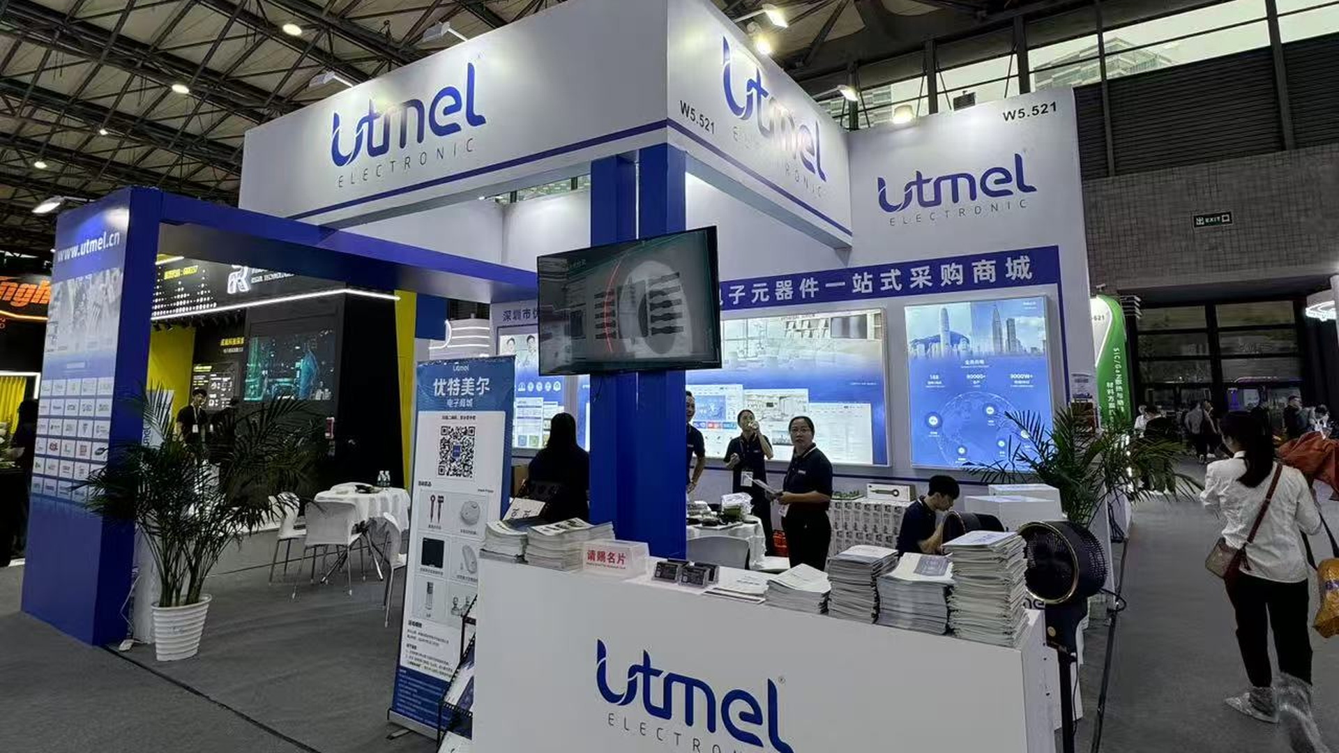 UTMEL Showcases One-Stop Electronic Component Sourcing Services at electronica Shanghai 2026
07 July 2026100
 Chip Filters, Piezoelectric Materials and the Piezoelectric Effect
27 September 20226966
 VRAM (Video RAM) Explained
03 June 20219697
Intersil (Renesas Electronics America)
In Stock: 3455
Minimum: 1 Multiples: 1
Qty
Unit Price
Ext Price
1
$3.196600
$3.20
10
$3.015660
$30.16
100
$2.844963
$284.50
500
$2.683927
$1,341.96
1000
$2.532007
$2,532.01
Not the price you want? Send RFQ Now and we'll contact you ASAP.
Inquire for More Quantity
![ISL80101IRAJZ]() ISL80101IRAJZ
ISL80101IRAJZIntersil (Renesas Electronics America)
![ISL80101IRAJZ-TK]() ISL80101IRAJZ-TK
ISL80101IRAJZ-TKIntersil (Renesas Electronics America)
![ICL7663SCPA]() ICL7663SCPA
ICL7663SCPAIntersil (Renesas Electronics America)
![ISL80102IRAJZ]() ISL80102IRAJZ
ISL80102IRAJZIntersil (Renesas Electronics America)
![ISL80136IBEAJZ-T7A]() ISL80136IBEAJZ-T7A
ISL80136IBEAJZ-T7AIntersil (Renesas Electronics America)
![ISL80103IRAJZ-T]() ISL80103IRAJZ-T
ISL80103IRAJZ-TIntersil (Renesas Electronics America)
![ICL7663SAIPA]() ICL7663SAIPA
ICL7663SAIPAIntersil (Renesas Electronics America)
![ISL80101IRAJZ-T]() ISL80101IRAJZ-T
ISL80101IRAJZ-TIntersil (Renesas Electronics America)
![ISL9021AIRUNZ-T]() ISL9021AIRUNZ-T
ISL9021AIRUNZ-TIntersil (Renesas Electronics America)
![ISL80101IR18Z-TK]() ISL80101IR18Z-TK
ISL80101IR18Z-TKIntersil (Renesas Electronics America)


