Product
 Brand
Brand Articles
 Tools
Tools
PC817 Optoisolators Transistor Photovoltaic 4DIP[Video]: Pinout, Datasheet, and Equivalents


OPTOISOLATOR 5KV TRANS 4DIP
PC817 Series contains an IRED optically coupled to a phototransistor. This article is going to talk about more detailed information about PC817.
How Optocouplers work - opto-isolator solid state relays phototransistor
Overview of PC817
An infrared diode and a phototransistor make up the PC817 optoisolator. To reduce noise from electric circuits, we primarily employ filters. The capacitor and resistor circuit always reduces noise from the incoming signal, but the capacitor and resistor values are always dependent on the incoming signal. This circuit is only useful when the incoming signal contains some information or data; however, if we only need to convey a signal from one portion of the circuit to another but the signal contains noise, we can use the IR sender and receive circuit.
PC817 Features
1. 4pin DIP package
2. Double transfer mold package (Ideal for Flow Soldering)
3. High collector-emitter voltage (VCEO:80V(*))
4. Current transfer ratio (CTR: MIN. 50% at IF=5 mA, VCE=5V)
5. Several CTR ranks are available
6. High isolation voltage between input and output
PC817 Pinout
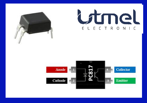
PC817 Pinout
| Pin Number | Pin Name | Description |
| 1 | Anode | Anode pin of the IR LED. Connected to the logic input |
| 2 | Cathode | Cathode pin of the IR LED. Connected to ground |
| 3 | Emitter | Emitter pin of the transistor. Connected to Ground |
| 4 | Collector | Collector pin of the Transistor. Provides logical output |
PC817 Dimensions

PC817 Dimensions
PC817 Block Diagram
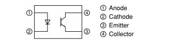
PC817 Block Diagram
Specifications
- TypeParameter
- Mount
In electronic components, the term "Mount" typically refers to the method or process of physically attaching or fixing a component onto a circuit board or other electronic device. This can involve soldering, adhesive bonding, or other techniques to secure the component in place. The mounting process is crucial for ensuring proper electrical connections and mechanical stability within the electronic system. Different components may have specific mounting requirements based on their size, shape, and function, and manufacturers provide guidelines for proper mounting procedures to ensure optimal performance and reliability of the electronic device.
Through Hole - Mounting Type
The "Mounting Type" in electronic components refers to the method used to attach or connect a component to a circuit board or other substrate, such as through-hole, surface-mount, or panel mount.
Through Hole - Package / Case
refers to the protective housing that encases an electronic component, providing mechanical support, electrical connections, and thermal management.
4-DIP (0.300, 7.62mm) - Number of Pins4
- Collector-Emitter Breakdown Voltage35V
- Collector-Emitter Saturation Voltage200mV
- Current Transfer Ratio-Min50% @ 5mA
- Number of Elements1
- Operating Temperature
The operating temperature is the range of ambient temperature within which a power supply, or any other electrical equipment, operate in. This ranges from a minimum operating temperature, to a peak or maximum operating temperature, outside which, the power supply may fail.
-30°C~100°C - Packaging
Semiconductor package is a carrier / shell used to contain and cover one or more semiconductor components or integrated circuits. The material of the shell can be metal, plastic, glass or ceramic.
Tube - Published2003
- JESD-609 Code
The "JESD-609 Code" in electronic components refers to a standardized marking code that indicates the lead-free solder composition and finish of electronic components for compliance with environmental regulations.
e0 - Part Status
Parts can have many statuses as they progress through the configuration, analysis, review, and approval stages.
Obsolete - Moisture Sensitivity Level (MSL)
Moisture Sensitivity Level (MSL) is a standardized rating that indicates the susceptibility of electronic components, particularly semiconductors, to moisture-induced damage during storage and the soldering process, defining the allowable exposure time to ambient conditions before they require special handling or baking to prevent failures
1 (Unlimited) - Terminal Finish
Terminal Finish refers to the surface treatment applied to the terminals or leads of electronic components to enhance their performance and longevity. It can improve solderability, corrosion resistance, and overall reliability of the connection in electronic assemblies. Common finishes include nickel, gold, and tin, each possessing distinct properties suitable for various applications. The choice of terminal finish can significantly impact the durability and effectiveness of electronic devices.
Tin/Lead (Sn/Pb) - Max Power Dissipation
The maximum power that the MOSFET can dissipate continuously under the specified thermal conditions.
200mW - Approval Agency
The parameter "Approval Agency" in electronic components refers to the organization responsible for testing and certifying that a component meets specific safety, quality, and performance standards. These agencies evaluate products to ensure compliance with industry regulations and standards, providing assurance to manufacturers and consumers. Approval from recognized agencies can enhance a component's marketability and acceptance in various applications, particularly in sectors like automotive, aerospace, and healthcare. Common approval agencies include Underwriters Laboratories (UL), International Electrotechnical Commission (IEC), and the American National Standards Institute (ANSI).
UL - Voltage - Isolation
Voltage - Isolation is a parameter in electronic components that refers to the maximum voltage that can be safely applied between two isolated points without causing electrical breakdown or leakage. It is a crucial specification for components such as transformers, optocouplers, and capacitors that require isolation to prevent electrical interference or safety hazards. The voltage isolation rating ensures that the component can withstand the specified voltage without compromising its performance or safety. It is typically measured in volts and is an important consideration when designing circuits that require isolation between different parts of the system.
5000Vrms - Output Voltage
Output voltage is a crucial parameter in electronic components that refers to the voltage level produced by the component as a result of its operation. It represents the electrical potential difference between the output terminal of the component and a reference point, typically ground. The output voltage is a key factor in determining the performance and functionality of the component, as it dictates the level of voltage that will be delivered to the connected circuit or load. It is often specified in datasheets and technical specifications to ensure compatibility and proper functioning within a given system.
80V - Output Type
The "Output Type" parameter in electronic components refers to the type of signal or data that is produced by the component as an output. This parameter specifies the nature of the output signal, such as analog or digital, and can also include details about the voltage levels, current levels, frequency, and other characteristics of the output signal. Understanding the output type of a component is crucial for ensuring compatibility with other components in a circuit or system, as well as for determining how the output signal can be utilized or processed further. In summary, the output type parameter provides essential information about the nature of the signal that is generated by the electronic component as its output.
Transistor - Configuration
The parameter "Configuration" in electronic components refers to the specific arrangement or setup of the components within a circuit or system. It encompasses how individual elements are interconnected and their physical layout. Configuration can affect the functionality, performance, and efficiency of the electronic system, and may influence factors such as signal flow, impedance, and power distribution. Understanding the configuration is essential for design, troubleshooting, and optimizing electronic devices.
SINGLE - Power Dissipation
the process by which an electronic or electrical device produces heat (energy loss or waste) as an undesirable derivative of its primary action.
200mW - Voltage - Forward (Vf) (Typ)
The parameter "Voltage - Forward (Vf) (Typ)" in electronic components refers to the typical forward voltage drop across the component when it is conducting current in the forward direction. It is a crucial characteristic of components like diodes and LEDs, indicating the minimum voltage required for the component to start conducting current. The forward voltage drop is typically specified as a typical value because it can vary slightly based on factors such as temperature and manufacturing tolerances. Designers use this parameter to ensure that the component operates within its specified voltage range and to calculate power dissipation in the component.
1.2V - Input Type
Input type in electronic components refers to the classification of the signal or data that a component can accept for processing or conversion. It indicates whether the input is analog, digital, or a specific format such as TTL or CMOS. Understanding input type is crucial for ensuring compatibility between different electronic devices and circuits, as it determines how signals are interpreted and interacted with.
DC - Forward Current
Current which flows upon application of forward voltage.
50mA - Output Current per Channel
Output Current per Channel is a specification commonly found in electronic components such as amplifiers, audio interfaces, and power supplies. It refers to the maximum amount of electrical current that can be delivered by each individual output channel of the component. This parameter is important because it determines the capacity of the component to drive connected devices or loads. A higher output current per channel means the component can deliver more power to connected devices, while a lower output current may limit the performance or functionality of the component in certain applications. It is crucial to consider the output current per channel when selecting electronic components to ensure they can meet the power requirements of the intended system or setup.
50mA - Rise Time
In electronics, when describing a voltage or current step function, rise time is the time taken by a signal to change from a specified low value to a specified high value.
18μs - Fall Time (Typ)
Fall Time (Typ) is a parameter used to describe the time it takes for a signal to transition from a high level to a low level in an electronic component, such as a transistor or an integrated circuit. It is typically measured in nanoseconds or microseconds and is an important characteristic that affects the performance of the component in digital circuits. A shorter fall time indicates faster switching speeds and can result in improved overall circuit performance, such as reduced power consumption and increased data transmission rates. Designers often consider the fall time specification when selecting components for their circuits to ensure proper functionality and efficiency.
18 μs - Collector Emitter Voltage (VCEO)
Collector-Emitter Voltage (VCEO) is a key parameter in electronic components, particularly in transistors. It refers to the maximum voltage that can be applied between the collector and emitter terminals of a transistor while the base terminal is open or not conducting. Exceeding this voltage limit can lead to breakdown and potential damage to the transistor. VCEO is crucial for ensuring the safe and reliable operation of the transistor within its specified limits. Designers must carefully consider VCEO when selecting transistors for a circuit to prevent overvoltage conditions that could compromise the performance and longevity of the component.
80V - Max Collector Current
Max Collector Current is a parameter used to specify the maximum amount of current that can safely flow through the collector terminal of a transistor or other electronic component without causing damage. It is typically expressed in units of amperes (A) and is an important consideration when designing circuits to ensure that the component operates within its safe operating limits. Exceeding the specified max collector current can lead to overheating, degradation of performance, or even permanent damage to the component. Designers must carefully consider this parameter when selecting components and designing circuits to ensure reliable and safe operation.
50mA - Rise / Fall Time (Typ)
The parameter "Rise / Fall Time (Typ)" in electronic components refers to the time it takes for a signal to transition from a specified low level to a specified high level (rise time) or from a high level to a low level (fall time). It is typically measured in nanoseconds or picoseconds and is an important characteristic in determining the speed and performance of a component, such as a transistor or integrated circuit. A shorter rise/fall time indicates faster signal switching and can impact the overall speed and efficiency of a circuit. Designers often consider this parameter when selecting components for high-speed applications to ensure proper signal integrity and timing.
4μs 3μs - Reverse Breakdown Voltage
Reverse Breakdown Voltage is the maximum reverse voltage a semiconductor device can withstand before it starts to conduct heavily in the reverse direction. It is a critical parameter in diodes and other components, indicating the threshold at which the material's insulating properties fail. Beyond this voltage, the device may enter a breakdown region, leading to potential damage if not properly managed. This parameter is essential for ensuring safe operation and reliability in electronic circuits.
6V - Max Input Current
Max Input Current is a parameter that specifies the maximum amount of electrical current that can safely flow into an electronic component without causing damage. It is an important consideration when designing or using electronic circuits to ensure that the component operates within its specified limits. Exceeding the maximum input current can lead to overheating, component failure, or even pose safety risks. Manufacturers provide this parameter in datasheets to help engineers and users understand the limitations of the component and ensure proper operation within the specified parameters.
50mA - Max Breakdown Voltage
The "Max Breakdown Voltage" of an electronic component refers to the maximum voltage that the component can withstand across its terminals before it breaks down and allows current to flow uncontrollably. This parameter is crucial in determining the operating limits and safety margins of the component in a circuit. Exceeding the maximum breakdown voltage can lead to permanent damage or failure of the component. It is typically specified by the manufacturer in datasheets to guide engineers and designers in selecting the appropriate components for their applications.
35V - Current Transfer Ratio (Max)
The "Current Transfer Ratio (Max)" is a parameter used to describe the efficiency of a specific type of electronic component known as an optocoupler or optoisolator. This parameter indicates the maximum ratio of output current to input current that can be achieved under ideal conditions. In simpler terms, it quantifies how effectively the optocoupler can transfer an electrical signal from its input side to its output side. A higher Current Transfer Ratio (Max) value typically indicates better performance and stronger signal transmission capabilities for the optocoupler. It is an important specification to consider when designing circuits that require isolation between different electrical systems or components.
600% @ 5mA - REACH SVHC
The parameter "REACH SVHC" in electronic components refers to the compliance with the Registration, Evaluation, Authorization, and Restriction of Chemicals (REACH) regulation regarding Substances of Very High Concern (SVHC). SVHCs are substances that may have serious effects on human health or the environment, and their use is regulated under REACH to ensure their safe handling and minimize their impact.Manufacturers of electronic components need to declare if their products contain any SVHCs above a certain threshold concentration and provide information on the safe use of these substances. This information allows customers to make informed decisions about the potential risks associated with using the components and take appropriate measures to mitigate any hazards.Ensuring compliance with REACH SVHC requirements is essential for electronics manufacturers to meet regulatory standards, protect human health and the environment, and maintain transparency in their supply chain. It also demonstrates a commitment to sustainability and responsible manufacturing practices in the electronics industry.
Yes - Radiation Hardening
Radiation hardening is the process of making electronic components and circuits resistant to damage or malfunction caused by high levels of ionizing radiation, especially for environments in outer space (especially beyond the low Earth orbit), around nuclear reactors and particle accelerators, or during nuclear accidents or nuclear warfare.
No - RoHS Status
RoHS means “Restriction of Certain Hazardous Substances” in the “Hazardous Substances Directive” in electrical and electronic equipment.
Non-RoHS Compliant - Lead Free
Lead Free is a term used to describe electronic components that do not contain lead as part of their composition. Lead is a toxic material that can have harmful effects on human health and the environment, so the electronics industry has been moving towards lead-free components to reduce these risks. Lead-free components are typically made using alternative materials such as silver, copper, and tin. Manufacturers must comply with regulations such as the Restriction of Hazardous Substances (RoHS) directive to ensure that their products are lead-free and environmentally friendly.
Contains Lead
PC817 Applications
I/O isolation for MCUs (Micro Controller Units)
Noise suppression in switching circuits
Signal transmission between circuits of different potentials and impedances
Electrical Isolation circuits
Microcontroller I/O switching circuits
Signal isolation
Noise coupling circuits
Isolation digital from analog circuits
Ac/DC Power control
Where to Use PC817 IC
A transistor in the PC817 Photocoupler is controlled by light (photon). So, within this IC, there's an IR (infrared) LED and a photo-transistor. When the IR LED is turned on, the light from it strikes the transistor, which causes it to conduct. The IR LED and photo-transistor is arranged and pinouts are listed below.
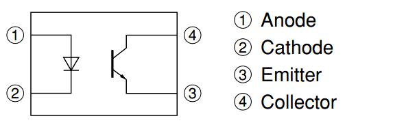
This IC provides electrical isolation between two circuits, one of which is coupled to an IR LED and the other to a photo-transistor. The IR LED's digital signal will be mirrored on the transistor, but there will be no hard electrical connection between them. This is highly useful when trying to separate a noisy signal from your digital electronics, so if you're looking for an IC to provide optical isolation in your circuit design, this IC can be the appropriate fit.
How to use PC817 IC
The PC817 IC is really simple to use; all we have to do is connect the anode pin of the IR LED (pin 1) to an isolated logic input and the cathode (pin 2) of the IR LED to the ground. Then, using a resistor (I used 1K here), pull high the collector pin of the transistor and link it to the output of your preferred logic circuit. The Emitter (pin 4) is connected to the ground.
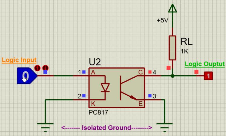
When the Logic input is low, the IR LED will not light up, and the transistor will be turned off. As a result, the logic output will remain high; this high voltage can be adjusted anywhere between +5V and 30V (Collector-Emitter Voltage), but I've used +5V in this example. There is a load resistor in the form of a 1K pull-up resistor. However, when the Logic input is set to a high voltage of at least 1.25V (Diode Forward voltage), the IR LED conducts and the photo-transistor is activated. As a result, the collector and emitter will be shorted, and the Logic Output voltage will be zero. The logic input will be reflected at the logic output in this manner while maintaining isolation between the two. The complete work can also be understood from the GIF file above.
The rise time (tr) and fall time are two more significant parameters to consider when employing an Optocoupler. When the input logic is made low, the output does not become high, and vice versa. The time it takes for the output to transition from one state to the next is shown in the waveform below. The rising time (TPDHL) and fall time (TPDLH) for PC817 are both 18us.
PC817 Package information
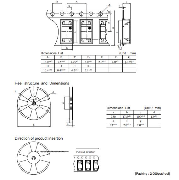
PC817 Package information
PC817 Manufacturer
Sharp Microelectronics of the Americas (SMA) drives innovative LCD, optoelectronics, memory, imager, and RF components to market. The world's leading manufacturers of consumer and business technologies look to SMA for the products, expertise, and worldwide support they need to make their visions a reality. SMA, in Camas, Washington, is the microelectronics sales and marketing division of Sharp Electronics Corporation, a wholly-owned subsidiary of Sharp Corporation.
Datasheet PDF
- Datasheets :
Popularity by Region
What is PC817?
Optocoupler / optoisolator is another name for PC817. It is made up of an Infrared Emitting Diode (IRED). This IRED is optically connected to a phototransistor rather than electrically. It's packaged in four-pin packaging. This package is usually offered in two variations.
Why is Optocoupler Used?
An Optocoupler may effectively remove electrical noise from signals when utilized correctly. Low-voltage devices should be kept separate from high-voltage circuits. Allows you to regulate bigger AC voltages with little digital signals.
How Does PC817 Work?
The IR receives the noisy signal as power from one circuit and sends it to the other component through the IR signal in the PC817 photoisolator IC circuit. The other component receives the signal and then executes the circuit design.
What is difference between optocoupler and opto isolator?
While optocouplers have the advantage of intrinsic external field immunity, the CMOS digital isolator has nearly similar field rejection due to the close matching of signal levels on each side of the internal differential signal route and good receiver selectivity.
What is the function of opto-isolator?
An optoisolator is an electronics device that provides electrical isolation between two circuits while transferring electrical energy from one circuit to another using a brief optical transmission route.
 6N136 Transistor: Circuit, Pinout, and Datasheet
09 December 20219273
 STM32F072RBT6 Microcontroller: 48MHz, 64-LQFP, Pinout and Datasheet
17 February 20221742
![The Guide to MB10S Bridge Rectifier [FAQ]](https://res.utmel.com/Images/Article/bf4fed82-00be-4c7c-a27e-aa20aab48310.jpg) The Guide to MB10S Bridge Rectifier [FAQ]
The Guide to MB10S Bridge Rectifier [FAQ]18 April 20226148
 TPS92630QPWPRQ1 LED Driver: Pinout, Manufacturer, and Datasheet
23 March 2022350
 HC-06 Bluetooth Module: Pinout, Datasheet pdf and Arduino Connection
23 November 202127925
 A Comprehensive Guide to LTC7106EDDB-1#TRMPBF Digital to Analog Converter
06 March 2024172
 LD1117S33CTR LDO Voltage Regulator: 3.3V 950mA, LD1117S33CTR Datasheet and Circuit
12 January 20223432
 MIC4605 MOSFET Driver: Pinout, Equivalent and Datasheet
16 December 20213123
 How many Transistors in a CPU?
15 April 202568179
 Introduction to MSP430 Microcontroller
26 December 202512366
 Semiconductor Materials:Types, Properties and Production Process
21 October 202526257
 Electric Car Rechargeable Batteries: How Long Do They Last?
13 April 20234137
 HDMI RF Modulators: Architecture, Setup, Types, and Commercial Applications
18 May 2026334
 What is Field Programmable Gate Array?
29 September 20203887
 Enhancing Frequency Stability in Modern Distributed Power Systems
21 September 20244347
 Analysis of SiP (System in Package)
12 January 20228736
Sharp Microelectronics
In Stock
United States
China
Canada
Japan
Russia
Germany
United Kingdom
Singapore
Italy
Hong Kong(China)
Taiwan(China)
France
Korea
Mexico
Netherlands
Malaysia
Austria
Spain
Switzerland
Poland
Thailand
Vietnam
India
United Arab Emirates
Afghanistan
Åland Islands
Albania
Algeria
American Samoa
Andorra
Angola
Anguilla
Antigua & Barbuda
Argentina
Armenia
Aruba
Australia
Azerbaijan
Bahamas
Bahrain
Bangladesh
Barbados
Belarus
Belgium
Belize
Benin
Bermuda
Bhutan
Bolivia
Bonaire, Sint Eustatius and Saba
Bosnia & Herzegovina
Botswana
Brazil
British Indian Ocean Territory
British Virgin Islands
Brunei
Bulgaria
Burkina Faso
Burundi
Cabo Verde
Cambodia
Cameroon
Cayman Islands
Central African Republic
Chad
Chile
Christmas Island
Cocos (Keeling) Islands
Colombia
Comoros
Congo
Congo (DRC)
Cook Islands
Costa Rica
Côte d’Ivoire
Croatia
Cuba
Curaçao
Cyprus
Czechia
Denmark
Djibouti
Dominica
Dominican Republic
Ecuador
Egypt
El Salvador
Equatorial Guinea
Eritrea
Estonia
Eswatini
Ethiopia
Falkland Islands
Faroe Islands
Fiji
Finland
French Guiana
French Polynesia
Gabon
Gambia
Georgia
Ghana
Gibraltar
Greece
Greenland
Grenada
Guadeloupe
Guam
Guatemala
Guernsey
Guinea
Guinea-Bissau
Guyana
Haiti
Honduras
Hungary
Iceland
Indonesia
Iran
Iraq
Ireland
Isle of Man
Israel
Jamaica
Jersey
Jordan
Kazakhstan
Kenya
Kiribati
Kosovo
Kuwait
Kyrgyzstan
Laos
Latvia
Lebanon
Lesotho
Liberia
Libya
Liechtenstein
Lithuania
Luxembourg
Macao(China)
Madagascar
Malawi
Maldives
Mali
Malta
Marshall Islands
Martinique
Mauritania
Mauritius
Mayotte
Micronesia
Moldova
Monaco
Mongolia
Montenegro
Montserrat
Morocco
Mozambique
Myanmar
Namibia
Nauru
Nepal
New Caledonia
New Zealand
Nicaragua
Niger
Nigeria
Niue
Norfolk Island
North Korea
North Macedonia
Northern Mariana Islands
Norway
Oman
Pakistan
Palau
Palestinian Authority
Panama
Papua New Guinea
Paraguay
Peru
Philippines
Pitcairn Islands
Portugal
Puerto Rico
Qatar
Réunion
Romania
Rwanda
Samoa
San Marino
São Tomé & Príncipe
Saudi Arabia
Senegal
Serbia
Seychelles
Sierra Leone
Sint Maarten
Slovakia
Slovenia
Solomon Islands
Somalia
South Africa
South Sudan
Sri Lanka
St Helena, Ascension, Tristan da Cunha
St. Barthélemy
St. Kitts & Nevis
St. Lucia
St. Martin
St. Pierre & Miquelon
St. Vincent & Grenadines
Sudan
Suriname
Svalbard & Jan Mayen
Sweden
Syria
Tajikistan
Tanzania
Timor-Leste
Togo
Tokelau
Tonga
Trinidad & Tobago
Tunisia
Turkey
Turkmenistan
Turks & Caicos Islands
Tuvalu
U.S. Outlying Islands
U.S. Virgin Islands
Uganda
Ukraine
Uruguay
Uzbekistan
Vanuatu
Vatican City
Venezuela
Wallis & Futuna
Yemen
Zambia
Zimbabwe
![PC123Y23FZ9F]() PC123Y23FZ9F
PC123Y23FZ9FSHARP/Socle Technology
![PC357N3J000F]() PC357N3J000F
PC357N3J000FSHARP/Socle Technology
![PC817X2NIP0F]() PC817X2NIP0F
PC817X2NIP0FSharp Microelectronics
![PC354NTJ000F]() PC354NTJ000F
PC354NTJ000FSharp Microelectronics
![PC817X2NIP1B]() PC817X2NIP1B
PC817X2NIP1BSHARP/Socle Technology
![PC817X1J000F]() PC817X1J000F
PC817X1J000FSharp Microelectronics
![PC357NTJ000F]() PC357NTJ000F
PC357NTJ000FSharp Microelectronics
![PC357N2TJ00F]() PC357N2TJ00F
PC357N2TJ00FSharp Microelectronics
![PC355NJ0000F]() PC355NJ0000F
PC355NJ0000FSHARP/Socle Technology
![PC367N2J000F]() PC367N2J000F
PC367N2J000FSHARP/Socle Technology