
 Product
 Brand
Brand Articles
 Tools
Tools
The Guide to MB10S Bridge Rectifier [FAQ]

Single Phase Bridge Rectifier Surface Mount -55°C~150°C TJ 5μA @ 1000V 1V @ 500mA TO-269AA, 4-BESOP Tape & Reel (TR)
Unit Price: $0.331590
Ext Price: $0.33


Single Phase Bridge Rectifier Surface Mount -55°C~150°C TJ 5μA @ 1000V 1V @ 500mA TO-269AA, 4-BESOP Tape & Reel (TR)
The MB10S from ON Semiconductor is an integrated full-bridge rectifier in a small SOIC-4 package. This article is going to explain features, specs, applications, circuits, and other details about the MB10S bridge rectifier for your reference.

how to check smd bridge rectifier diode MB10S
What is MB10S?
The MB10S is a 0.5 A rectifier that achieves strong surge current absorption while having a small footprint.
The MB10S impresses in its surge capability despite its compact 35 mm2 form factor. The design supports a 35 A IFSM rating and a 5.0 A2Sec I2T rating to sustain strong surge currents. Breakdown voltages of up to 1000 V are also rated for devices in the family. The MB10S qualities make it excellent for small power supplies that require a bit of extra surge protection.
MB10S Pinout

MB10S Pinout
| Pin Number | Pin Name | Description |
| 1 | + | Output positive terminal |
| 2 | - | Output negative terminal |
| 3 | ~ | AC input terminal |
| 4 | ~ | AC input terminal |
MB10S CAD Model

MB10S Symbol

MB10S Footprint

MB10S 3D Model
Specifications
- TypeParameter
- Lifecycle Status
Lifecycle Status refers to the current stage of an electronic component in its product life cycle, indicating whether it is active, obsolete, or transitioning between these states. An active status means the component is in production and available for purchase. An obsolete status indicates that the component is no longer being manufactured or supported, and manufacturers typically provide a limited time frame for support. Understanding the lifecycle status is crucial for design engineers to ensure continuity and reliability in their projects.
ACTIVE (Last Updated: 2 days ago) - Factory Lead Time12 Weeks
- Contact Plating
Contact plating (finish) provides corrosion protection for base metals and optimizes the mechanical and electrical properties of the contact interfaces.
Tin - Mount
In electronic components, the term "Mount" typically refers to the method or process of physically attaching or fixing a component onto a circuit board or other electronic device. This can involve soldering, adhesive bonding, or other techniques to secure the component in place. The mounting process is crucial for ensuring proper electrical connections and mechanical stability within the electronic system. Different components may have specific mounting requirements based on their size, shape, and function, and manufacturers provide guidelines for proper mounting procedures to ensure optimal performance and reliability of the electronic device.
Surface Mount - Mounting Type
The "Mounting Type" in electronic components refers to the method used to attach or connect a component to a circuit board or other substrate, such as through-hole, surface-mount, or panel mount.
Surface Mount - Package / Case
refers to the protective housing that encases an electronic component, providing mechanical support, electrical connections, and thermal management.
TO-269AA, 4-BESOP - Number of Pins4
- Supplier Device Package
The parameter "Supplier Device Package" in electronic components refers to the physical packaging or housing of the component as provided by the supplier. It specifies the form factor, dimensions, and layout of the component, which are crucial for compatibility and integration into electronic circuits and systems. The supplier device package information typically includes details such as the package type (e.g., DIP, SOP, QFN), number of pins, pitch, and overall size, allowing engineers and designers to select the appropriate component for their specific application requirements. Understanding the supplier device package is essential for proper component selection, placement, and soldering during the manufacturing process to ensure optimal performance and reliability of the electronic system.
4-SOIC - Weight228mg
- Number of Elements1
- Voltage Rated
RATED voltage is the voltage on the nameplate - the "design point" for maximum power throughput and safe thermal operation.
500V - Operating Temperature
The operating temperature is the range of ambient temperature within which a power supply, or any other electrical equipment, operate in. This ranges from a minimum operating temperature, to a peak or maximum operating temperature, outside which, the power supply may fail.
-55°C~150°C TJ - Packaging
Semiconductor package is a carrier / shell used to contain and cover one or more semiconductor components or integrated circuits. The material of the shell can be metal, plastic, glass or ceramic.
Tape & Reel (TR) - Published2013
- Tolerance
In electronic components, "tolerance" refers to the acceptable deviation or variation from the specified or ideal value of a particular parameter, such as resistance, capacitance, or voltage. It indicates the range within which the actual value of the component can fluctuate while still being considered acceptable for use in a circuit. Tolerance is typically expressed as a percentage or a specific value and is important for ensuring the accuracy and reliability of electronic devices. Components with tighter tolerances are more precise but may also be more expensive. It is crucial to consider tolerance when selecting components to ensure proper functionality and performance of the circuit.
10% - Part Status
Parts can have many statuses as they progress through the configuration, analysis, review, and approval stages.
Active - Moisture Sensitivity Level (MSL)
Moisture Sensitivity Level (MSL) is a standardized rating that indicates the susceptibility of electronic components, particularly semiconductors, to moisture-induced damage during storage and the soldering process, defining the allowable exposure time to ambient conditions before they require special handling or baking to prevent failures
1 (Unlimited) - Max Operating Temperature
The Maximum Operating Temperature is the maximum body temperature at which the thermistor is designed to operate for extended periods of time with acceptable stability of its electrical characteristics.
150°C - Min Operating Temperature
The "Min Operating Temperature" parameter in electronic components refers to the lowest temperature at which the component is designed to operate effectively and reliably. This parameter is crucial for ensuring the proper functioning and longevity of the component, as operating below this temperature may lead to performance issues or even damage. Manufacturers specify the minimum operating temperature to provide guidance to users on the environmental conditions in which the component can safely operate. It is important to adhere to this parameter to prevent malfunctions and ensure the overall reliability of the electronic system.
-55°C - Capacitance
Capacitance is a fundamental electrical property of electronic components that describes their ability to store electrical energy in the form of an electric field. It is measured in farads (F) and represents the ratio of the amount of electric charge stored on a component to the voltage across it. Capacitors are passive components that exhibit capacitance and are commonly used in electronic circuits for various purposes such as filtering, energy storage, timing, and coupling. Capacitance plays a crucial role in determining the behavior and performance of electronic systems by influencing factors like signal propagation, frequency response, and power consumption.
470pF - Max Power Dissipation
The maximum power that the MOSFET can dissipate continuously under the specified thermal conditions.
1.4W - Base Part Number
The "Base Part Number" (BPN) in electronic components serves a similar purpose to the "Base Product Number." It refers to the primary identifier for a component that captures the essential characteristics shared by a group of similar components. The BPN provides a fundamental way to reference a family or series of components without specifying all the variations and specific details.
MB10 - Case Code (Metric)
Case Code (Metric) in electronic components refers to a standardized system that specifies the dimensions of surface-mount devices (SMD) in millimeters, consisting of a four-digit number where the first two digits represent the width and the last two digits represent the height of the component, measured in tenths of a millimeter. The metric case codes are standardized by organizations such as the EIA and IEC, and are often compared to the Imperial code which uses inches, allowing for easier identification and selection of components across different regions and industries. This coding system is widely used in the design and manufacturing of electronic devices, particularly in applications requiring compact and efficient component layouts, and is essential for engineers and designers to ensure proper component selection and facilitate the assembly process in electronic manufacturing.
3216 - Case Code (Imperial)
The term "Case Code (Imperial)" in electronic components refers to a standardized system used to specify the physical dimensions and package types of components, particularly capacitors and resistors. This code helps manufacturers and engineers identify the size and form factor of the component, ensuring compatibility with circuit designs and PCB layouts. In the context of electronic components, the Case Code (Imperial) typically follows a numerical format that indicates the length and width of the component in inches. For example, a Case Code of 1206 signifies a component that measures 0.12 inches by 0.06 inches. This coding system is essential for selecting the correct components for specific applications, as it provides a quick reference to the physical characteristics of the part, including its footprint and mounting style.
1206 - Lead Pitch
Lead pitch in electronic components refers to the distance between the center of one lead (or pin) of a component to the center of the adjacent lead. It is an important parameter to consider when designing and assembling electronic circuits, as it determines the spacing required on a circuit board for proper placement and soldering of the component. Lead pitch is typically specified in millimeters or inches and can vary depending on the type of component, such as integrated circuits, resistors, capacitors, and connectors. Choosing the correct lead pitch ensures proper alignment and connection of components on a circuit board, ultimately affecting the functionality and reliability of the electronic device.
5.0038mm - Element Configuration
The distribution of electrons of an atom or molecule (or other physical structure) in atomic or molecular orbitals.
Single - Diode Type
In electronic components, the parameter "Diode Type" refers to the specific type or configuration of a diode, which is a semiconductor device that allows current to flow in one direction only. There are various types of diodes, each designed for specific applications and functions. Common diode types include rectifier diodes, zener diodes, light-emitting diodes (LEDs), and Schottky diodes, among others. The diode type determines the diode's characteristics, such as forward voltage drop, reverse breakdown voltage, and maximum current rating, making it crucial for selecting the right diode for a particular circuit or application. Understanding the diode type is essential for ensuring proper functionality and performance in electronic circuits.
Single Phase - Current - Reverse Leakage @ Vr
Current - Reverse Leakage @ Vr is a parameter that describes the amount of current that flows in the reverse direction through a diode or other semiconductor component when a reverse voltage (Vr) is applied across it. This leakage current is typically very small, but it is important to consider in electronic circuits as it can affect the overall performance and reliability of the component. The reverse leakage current is influenced by factors such as the material properties of the semiconductor, temperature, and the magnitude of the reverse voltage applied. Manufacturers provide this parameter in datasheets to help engineers and designers understand the behavior of the component in reverse bias conditions.
5μA @ 1000V - Voltage - Forward (Vf) (Max) @ If
The parameter "Voltage - Forward (Vf) (Max) @ If" refers to the maximum voltage drop across a diode when it is forward-biased and conducting a specified forward current (If). It indicates the maximum potential difference the diode can withstand while allowing current to flow in the forward direction without breaking down. This value is crucial for designing circuits as it helps determine how much voltage will be lost across the diode during operation. Higher Vf values can lead to reduced efficiency in power applications, making this parameter essential for optimizing circuit performance.
1V @ 500mA - Forward Current
Current which flows upon application of forward voltage.
800mA - Lead/Base Style
The parameter "Lead/Base Style" in electronic components refers to the physical configuration of the leads or terminals of the component in relation to its base or body. This parameter describes how the leads are attached to the component and how they are positioned in relation to the base. Common lead/base styles include through-hole, surface mount, gull-wing, J-lead, and many others. Understanding the lead/base style is important for proper installation and connection of the component in a circuit, as different styles may require different soldering techniques or mounting considerations.
Formed Leads - Max Surge Current
Surge current is a peak non repetitive current. Maximum (peak or surge) forward current = IFSM or if(surge), the maximum peak amount of current the diode is able to conduct in forward bias mode.
35A - Current - Average Rectified (Io)
The parameter "Current - Average Rectified (Io)" in electronic components refers to the average value of the rectified current flowing through the component. This parameter is important in determining the average power dissipation and thermal considerations of the component. It is typically specified in datasheets for diodes, rectifiers, and other components that handle alternating current (AC) and convert it to direct current (DC). Understanding the average rectified current helps in selecting the appropriate component for a given application to ensure reliable operation and prevent overheating.
500mA - Forward Voltage
the amount of voltage needed to get current to flow across a diode.
1V - Average Rectified Current
Mainly used to characterize alternating voltage and current. It can be computed by averaging the absolute value of a waveform over one full period of the waveform.
500mA - Peak Reverse Current
The maximum voltage that a diode can withstand in the reverse direction without breaking down or avalanching.If this voltage is exceeded the diode may be destroyed. Diodes must have a peak inverse voltage rating that is higher than the maximum voltage that will be applied to them in a given application.
500μA - Max Repetitive Reverse Voltage (Vrrm)
The Max Repetitive Reverse Voltage (Vrrm) is a crucial parameter in electronic components, particularly in diodes and transistors. It refers to the maximum voltage that can be applied across the component in the reverse direction without causing damage. This parameter is important for ensuring the proper functioning and longevity of the component in circuits where reverse voltage may be present. Exceeding the Vrrm rating can lead to breakdown and failure of the component, so it is essential to carefully consider this specification when designing or selecting components for a circuit.
1kV - Peak Non-Repetitive Surge Current
Peak Non-Repetitive Surge Current is a specification in electronic components that refers to the maximum current that the component can withstand for a short duration without sustaining damage. This surge current typically occurs as a result of sudden voltage spikes or transient events in the circuit. It is important to consider this parameter when designing or selecting components to ensure they can handle occasional high-current surges without failing. The value of Peak Non-Repetitive Surge Current is usually specified in amperes and is crucial for protecting the component and maintaining the overall reliability of the circuit.
35A - Reverse Voltage
the voltage drop across the diode if the voltage at the cathode is more positive than the voltage at the anode
1kV - Max Forward Surge Current (Ifsm)
Max Forward Surge Current (Ifsm) is a parameter used to specify the maximum peak current that a diode or other electronic component can withstand for a short duration during a surge event. Surge currents can occur due to sudden changes in voltage or power supply fluctuations, and the Ifsm rating helps determine the component's ability to handle such transient overloads without being damaged. It is important to consider the Ifsm rating when selecting components for applications where surge currents are expected, such as in power supplies, motor drives, and other high-power circuits. Exceeding the Ifsm rating can lead to overheating, degradation, or failure of the component, so it is crucial to ensure that the chosen component can safely handle the expected surge currents in the circuit.
35A - Voltage - Peak Reverse (Max)
Voltage - Peak Reverse (Max) refers to the maximum voltage that a semiconductor device, typically a diode, can withstand in the reverse-bias direction without undergoing breakdown. It is crucial for ensuring reliable operation in circuits where the direction of the voltage may change. Exceeding this parameter can result in permanent damage to the component, leading to failure in its intended function. This specification is particularly important in applications involving rectification or signal modulation.
1kV - Max Junction Temperature (Tj)
Max Junction Temperature (Tj) refers to the maximum allowable temperature at the junction of a semiconductor device, such as a transistor or integrated circuit. It is a critical parameter that influences the performance, reliability, and lifespan of the component. Exceeding this temperature can lead to thermal runaway, breakdown, or permanent damage to the device. Proper thermal management is essential to ensure the junction temperature remains within safe operating limits during device operation.
150°C - Reverse Voltage (DC)
Reverse Voltage (DC) refers to the maximum voltage that an electronic component, typically a semiconductor device like a diode, can withstand in the reverse direction without undergoing breakdown or failure. It indicates the threshold at which the device will start to conduct in reverse, potentially damaging the component. This parameter is crucial for ensuring the reliability and safety of circuits that may experience reverse polarity or unexpected voltage conditions. Exceeding the specified reverse voltage can lead to permanent damage or catastrophic failure of the component.
1kV - Height2.9mm
- Height Seated (Max)
Height Seated (Max) is a parameter in electronic components that refers to the maximum allowable height of the component when it is properly seated or installed on a circuit board or within an enclosure. This specification is crucial for ensuring proper fit and alignment within the overall system design. Exceeding the maximum seated height can lead to mechanical interference, electrical shorts, or other issues that may impact the performance and reliability of the electronic device. Manufacturers provide this information to help designers and engineers select components that will fit within the designated space and function correctly in the intended application.
8.9916mm - Length4.95mm
- Width4.2mm
- Thickness
Thickness in electronic components refers to the measurement of how thick a particular material or layer is within the component structure. It can pertain to various aspects, such as the thickness of a substrate, a dielectric layer, or conductive traces. This parameter is crucial as it impacts the electrical, mechanical, and thermal properties of the component, influencing its performance and reliability in electronic circuits.
990.6μm - REACH SVHC
The parameter "REACH SVHC" in electronic components refers to the compliance with the Registration, Evaluation, Authorization, and Restriction of Chemicals (REACH) regulation regarding Substances of Very High Concern (SVHC). SVHCs are substances that may have serious effects on human health or the environment, and their use is regulated under REACH to ensure their safe handling and minimize their impact.Manufacturers of electronic components need to declare if their products contain any SVHCs above a certain threshold concentration and provide information on the safe use of these substances. This information allows customers to make informed decisions about the potential risks associated with using the components and take appropriate measures to mitigate any hazards.Ensuring compliance with REACH SVHC requirements is essential for electronics manufacturers to meet regulatory standards, protect human health and the environment, and maintain transparency in their supply chain. It also demonstrates a commitment to sustainability and responsible manufacturing practices in the electronics industry.
No SVHC - Radiation Hardening
Radiation hardening is the process of making electronic components and circuits resistant to damage or malfunction caused by high levels of ionizing radiation, especially for environments in outer space (especially beyond the low Earth orbit), around nuclear reactors and particle accelerators, or during nuclear accidents or nuclear warfare.
No - RoHS Status
RoHS means “Restriction of Certain Hazardous Substances” in the “Hazardous Substances Directive” in electrical and electronic equipment.
ROHS3 Compliant - Lead Free
Lead Free is a term used to describe electronic components that do not contain lead as part of their composition. Lead is a toxic material that can have harmful effects on human health and the environment, so the electronics industry has been moving towards lead-free components to reduce these risks. Lead-free components are typically made using alternative materials such as silver, copper, and tin. Manufacturers must comply with regulations such as the Restriction of Hazardous Substances (RoHS) directive to ensure that their products are lead-free and environmentally friendly.
Lead Free
MB10S Features
Low−Leakage
Surge Overload Rating: 35 A peak
Ideal for Printed Circuit Board
UL Certified: UL #E258596
This Device is Pb−Free and RoHS Compliant
Mechanical Data of MB10S
Case: MBS
Case Material: Molded Plastic.
UL Flammability Classification Rating 94V-0
Moisture Sensitivity: Level 1 per J-STD-020
Terminals: Lead-Free Plating (Matte Tin Finish). Solderable per MIL-STD-202, Method 208
Polarity: As Marked on Body
Weight: 0.11 grams (Approximate)
MB10S Applications
AC to DC bridge full-wave rectification for SMPS
LED lighting
Adapter
Miniature switching power supplies
Phone chargers
Mains powered appliances
battery charger
home appliances
office equipment
telecommunication applications
MB10S Equivalents
KBL04, DB107
Parts with Similar Specs
- ImagePart NumberManufacturerMountPackage / CaseForward VoltageReverse Voltage (DC)Average Rectified CurrentCurrent - Average Rectified (Io)Radiation HardeningMoisture Sensitivity Level (MSL)View Compare
![MB10S]()
MB10S
Surface Mount
TO-269AA, 4-BESOP
1 V
1 kV
500 mA
500mA
No
1 (Unlimited)
![MB6S]()
Surface Mount
TO-269AA, 4-BESOP
1 V
-
500 mA
500mA
No
1 (Unlimited)
![MB2S]()
Surface Mount
TO-269AA, 4-BESOP
1 V
-
500 mA
500mA
No
1 (Unlimited)
![MB8S]()
Surface Mount
TO-269AA, 4-BESOP
1 V
140 V
500 mA
500mA
No
1 (Unlimited)
![MB1S]()
Surface Mount
TO-269AA, 4-BESOP
1 V
560 V
500 mA
500mA
No
1 (Unlimited)


How to use MB10S?
The MB10S is an integrated full-bridge rectifier. It is made up of four diodes that are connected in a bridge configuration in one package. Normally, four individual diodes on a PCB are used to do this, but using an integrated solution like the MB10S saves space and evenly distributes power dissipation, whereas any of the four discrete diodes could fail. The internal circuit diagram of the MB10S is shown in the picture below.

MB10S Application Circuit
When dealing with switching supplies that demand a big decoupling capacitor after the rectifier, the 35A peak current rating comes in handy. This capacitor charges just at the positive and negative peaks of the input sine wave, putting a significant peak load on the rectifier (as illustrated in the diagram below) that the MB10S can handle.

MB10S Dimensions Outline

MB10S Dimensions Outline
MB10S Manufacturer
onsemi (legally ON Semiconductor Corporation; formerly ON Semiconductor until August 5, 2021) is an American semiconductor supplier company, formerly in the Fortune 500, but dropping into the Fortune 1000 (ranked 512) in 2020. Products include power and signal management, logic, discrete, and custom devices for automotive, communications, computing, consumer, industrial, LED lighting, medical, military/aerospace, and power applications.
What is the use of MB10S?
The MB10S is suitable for AC to DC bridge full-wave rectification for SMPS, LED lighting, adapter, battery charger, home appliances, office equipment, and telecommunication applications.
What is the compact size of the MB10S?
35 mm2 form factor
What does the MB10S require?
a bit of extra surge protection
What rating does the MB10S support to sustain strong surge currents?
35 A IFSM rating and a 5.0 A2Sec I2T rating
What is the operating range of MB10S?
-55°C~150°C TJ
 LM338K Voltage Regulator: Datasheet, Circuit, Alternatives
16 September 20215912
![IRLZ24N MOSFET: Pinout, Equivalents, IRLZ24N vs. FQP20N06L [Video]](https://res.utmel.com/Images/Article/90a61ffd-41de-4333-9cba-9706fa2df005.jpg) IRLZ24N MOSFET: Pinout, Equivalents, IRLZ24N vs. FQP20N06L [Video]
IRLZ24N MOSFET: Pinout, Equivalents, IRLZ24N vs. FQP20N06L [Video]14 September 20222134
 A Comprehensive Technical Guide to Microchip PIC16F1829TIML Microcontroller
29 February 2024216
 Decoding the Microchip PIC16F5X Series: Flash-Based 8-Bit CMOS Microcontrollers
29 February 2024225
 Navigating VN31 (VIPower) Obsolescence: Specs, Pinout, and Modern Replacements
12 February 2026104
 STM32F030F4P6 Microcontrollers: Scheme, Pinout, and Datasheet
17 November 20219568
 Ways to Pick Infineon IRLML6402TRPBF Online
18 August 2025284
 TPS62745DSSR: Step-Down, Datasheet, Ultra-Low Power
28 February 20224016
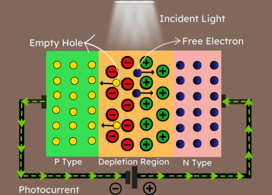 Understanding Photodiodes: Working Principles and Applications - Part 2
24 May 20245038
 The Complete Guide to DC-DC Converters
24 May 20252324
 What is a DC-to-DC Converter?
23 April 20217453
 What is a variable capacitor?
16 April 202563503
 NOR Flash: Working, Structure and Applications
18 November 202114452
 Parking Access Control System using Arduino
29 August 20236275
 What is ARM Processor?
17 March 20224777
 Exploring an Advanced Approach to Thermal Design for Dual-Sided Cooling of Power Semiconductor Modules in Electric and Hybrid Vehicles
07 September 2023926
ON Semiconductor
In Stock: 300
Minimum: 1 Multiples: 1
Qty
Unit Price
Ext Price
1
$0.331590
$0.33
10
$0.312821
$3.13
100
$0.295114
$29.51
500
$0.278409
$139.20
1000
$0.262650
$262.65
Not the price you want? Send RFQ Now and we'll contact you ASAP.
Inquire for More Quantity


