
 Product
 Brand
Brand Articles
 Tools
Tools
TDA7056B Audio Amplifiers: Schematic, Pinout, and Datasheet [Video&FAQ]


Audio Amplifiers 18V V 9-SIP Exposed Tab
The TDA7056B is a DC volume-controlled mono Bridge-Tied Load (BTL) output amplifier. This article mainly introduces schematic, pinout, datasheet and other detailed information about NXP Semiconductors TDA7056B.

How to make amplifier at home very easy |#amplifier| TDA7056b ic simple audio amplifier.
TDA7056B Description
The TDA7056B is a DC volume-controlled mono Bridge-Tied Load (BTL) output amplifier. It's intended for usage in televisions and monitors, but it can also be used in battery-powered portable recorders and radios. The gadget is housed in a medium power 9-pin box.
A MCL (Missing Current Limiter) is included. When the current difference between the output terminals of each amplifier exceeds 100 mA, the MCL circuit is engaged (300 mA typ). This current level of 100 mA is suitable for headphone use (single-ended).
TDA7056B Pinout
The following figure is the Pinout of TDA7056B.

Pinout
| Pin Number | Pin Name | Description |
| 1 | n.c. | not connected |
| 2 | VP | positive supply voltage |
| 3 | VI | voltage input |
| 4 | GND1 | signal ground |
| 5 | VC | DC volume control |
| 6 | OUT+ | positive output |
| 7 | GND2 | power ground |
| 8 | OUT- | negative output |
| 9 | n.c. | not connected |
TDA7056B CAD Model
The followings are the Symbol, Footprint of TDA7056B.

Symbol

Footprint
TDA7056B Features
• DC Volume Control
• Few External Components
• Mute Mode
• Thermal Protection
• Short-circuit Proof
• No Switch-on and Switch-off Clicks
• Good Overall Stability
• Low Power Consumption
• Low HF Radiation
• ESD Protected on All Pins
Specifications
- TypeParameter
- Mounting Type
The "Mounting Type" in electronic components refers to the method used to attach or connect a component to a circuit board or other substrate, such as through-hole, surface-mount, or panel mount.
Through Hole - Package / Case
refers to the protective housing that encases an electronic component, providing mechanical support, electrical connections, and thermal management.
9-SIP Exposed Tab - Surface Mount
having leads that are designed to be soldered on the side of a circuit board that the body of the component is mounted on.
NO - Operating Temperature
The operating temperature is the range of ambient temperature within which a power supply, or any other electrical equipment, operate in. This ranges from a minimum operating temperature, to a peak or maximum operating temperature, outside which, the power supply may fail.
-40°C~85°C TA - Packaging
Semiconductor package is a carrier / shell used to contain and cover one or more semiconductor components or integrated circuits. The material of the shell can be metal, plastic, glass or ceramic.
Tube - Published1996
- Part Status
Parts can have many statuses as they progress through the configuration, analysis, review, and approval stages.
Obsolete - Moisture Sensitivity Level (MSL)
Moisture Sensitivity Level (MSL) is a standardized rating that indicates the susceptibility of electronic components, particularly semiconductors, to moisture-induced damage during storage and the soldering process, defining the allowable exposure time to ambient conditions before they require special handling or baking to prevent failures
1 (Unlimited) - Number of Terminations9
- TypeClass AB
- HTS Code
HTS (Harmonized Tariff Schedule) codes are product classification codes between 8-1 digits. The first six digits are an HS code, and the countries of import assign the subsequent digits to provide additional classification. U.S. HTS codes are 1 digits and are administered by the U.S. International Trade Commission.
8542.33.00.01 - Voltage - Supply
Voltage - Supply refers to the range of voltage levels that an electronic component or circuit is designed to operate with. It indicates the minimum and maximum supply voltage that can be applied for the device to function properly. Providing supply voltages outside this range can lead to malfunction, damage, or reduced performance. This parameter is critical for ensuring compatibility between different components in a circuit.
4.5V~18V - Terminal Position
In electronic components, the term "Terminal Position" refers to the physical location of the connection points on the component where external electrical connections can be made. These connection points, known as terminals, are typically used to attach wires, leads, or other components to the main body of the electronic component. The terminal position is important for ensuring proper connectivity and functionality of the component within a circuit. It is often specified in technical datasheets or component specifications to help designers and engineers understand how to properly integrate the component into their circuit designs.
SINGLE - Number of Functions1
- Terminal Pitch
The center distance from one pole to the next.
2.54mm - Base Part Number
The "Base Part Number" (BPN) in electronic components serves a similar purpose to the "Base Product Number." It refers to the primary identifier for a component that captures the essential characteristics shared by a group of similar components. The BPN provides a fundamental way to reference a family or series of components without specifying all the variations and specific details.
TDA7056 - Pin Count
a count of all of the component leads (or pins)
9 - JESD-30 Code
JESD-30 Code refers to a standardized descriptive designation system established by JEDEC for semiconductor-device packages. This system provides a systematic method for generating designators that convey essential information about the package's physical characteristics, such as size and shape, which aids in component identification and selection. By using JESD-30 codes, manufacturers and engineers can ensure consistency and clarity in the specification of semiconductor packages across various applications and industries.
R-PSIP-T9 - Qualification Status
An indicator of formal certification of qualifications.
Not Qualified - Output Type
The "Output Type" parameter in electronic components refers to the type of signal or data that is produced by the component as an output. This parameter specifies the nature of the output signal, such as analog or digital, and can also include details about the voltage levels, current levels, frequency, and other characteristics of the output signal. Understanding the output type of a component is crucial for ensuring compatibility with other components in a circuit or system, as well as for determining how the output signal can be utilized or processed further. In summary, the output type parameter provides essential information about the nature of the signal that is generated by the electronic component as its output.
1-Channel (Mono) - Supply Voltage-Max (Vsup)
The parameter "Supply Voltage-Max (Vsup)" in electronic components refers to the maximum voltage that can be safely applied to the component without causing damage. It is an important specification to consider when designing or using electronic circuits to ensure the component operates within its safe operating limits. Exceeding the maximum supply voltage can lead to overheating, component failure, or even permanent damage. It is crucial to adhere to the specified maximum supply voltage to ensure the reliable and safe operation of the electronic component.
18V - Power Supplies
an electronic circuit that converts the voltage of an alternating current (AC) into a direct current (DC) voltage.?
12V - Supply Voltage-Min (Vsup)
The parameter "Supply Voltage-Min (Vsup)" in electronic components refers to the minimum voltage level required for the component to operate within its specified performance range. This parameter indicates the lowest voltage that can be safely applied to the component without risking damage or malfunction. It is crucial to ensure that the supply voltage provided to the component meets or exceeds this minimum value to ensure proper functionality and reliability. Failure to adhere to the specified minimum supply voltage may result in erratic behavior, reduced performance, or even permanent damage to the component.
4.5V - Number of Channels1
- Supply Current-Max
Supply Current-Max refers to the maximum amount of current that an electronic component or circuit can draw from its power supply under specified operating conditions. It is a critical parameter that determines the power consumption and thermal performance of the device. Exceeding this limit can lead to overheating, potential damage, or failure of the component. Knowing the Supply Current-Max helps in designing circuits that ensure proper operation and reliability.
13mA - Max Output Power x Channels @ Load
Max Output Power x Channels @ Load is a specification that describes the maximum power output that an electronic component, such as an amplifier or audio device, can deliver across a certain number of channels at a specific load impedance. This parameter is important for understanding the capability of the component to drive speakers or other devices effectively. The value is typically expressed in watts and can vary depending on the number of channels being used and the impedance of the load. It helps users determine the compatibility of the component with their audio setup and ensures that the component can provide sufficient power for optimal performance.
5.5W x 1 @ 8 Ω - Harmonic Distortion
Harmonic distortion is a common parameter used to describe the quality of audio or electronic signals. It refers to the presence of unwanted harmonics or additional frequencies in the output signal that were not present in the input signal. These harmonics are typically multiples of the original signal frequency and can distort the waveform, affecting the overall sound quality or performance of the electronic component. Lower harmonic distortion values indicate a cleaner and more accurate output signal, while higher distortion levels can result in a more distorted or altered sound. Manufacturers often specify harmonic distortion levels in percentage or decibels to help users understand the quality of the component's output.
0.3% - Features
In the context of electronic components, the term "Features" typically refers to the specific characteristics or functionalities that a particular component offers. These features can vary depending on the type of component and its intended use. For example, a microcontroller may have features such as built-in memory, analog-to-digital converters, and communication interfaces like UART or SPI.When evaluating electronic components, understanding their features is crucial in determining whether they meet the requirements of a particular project or application. Engineers and designers often look at features such as operating voltage, speed, power consumption, and communication protocols to ensure compatibility and optimal performance.In summary, the "Features" parameter in electronic components describes the unique attributes and capabilities that differentiate one component from another, helping users make informed decisions when selecting components for their electronic designs.
Depop, Mute, Short-Circuit and Thermal Protection, Volume Control - RoHS Status
RoHS means “Restriction of Certain Hazardous Substances” in the “Hazardous Substances Directive” in electrical and electronic equipment.
ROHS3 Compliant
TDA7056B Functional Block Diagram
The following figure is TDA7056B Functional Block Diagram.

Functional Block Diagram
TDA7056B Test and Application Information
The figures below show the Test And Application Information of TDA7056B.

Test and Application Diagram

Application with potentiometer as volume control; maximum gain = 34 dB

Application with potentiometer as volume control; maximum gain = 40 dB
TDA7056A VS TDA7056B
TDA7056A and TDA7056B have differences in a small number of electrical parameters, the basic functions are exactly the same, and they can be directly interchanged. In addition to the 3.5WBTL power amplifier circuit, this IC also has volume control, overheating protection and short-circuit protection and expansion functions. It has a wide operating voltage range (4.5-18V), few external components, and stable operation.
TDA7056B Simplified Schematic
TDA7056A and TDA7056B are two TDA7056 variations that are now more widely available. Although their performance and pinout are quite similar, they will not function in the same circuit.
TDA7056B appears to be the better of the two, with output power somewhat higher than 16 ohms and, this time, a reference power output of 5.5W for an 8-ohm speaker on the datasheet. Because it appears to be the best, this is the only chip I brought and tested.
TDA7056A/TDA7056B require at least two additional components than TDA7056. This is due to the fact that a DC volume control input must be grounded via a 1F capacitor. TDA7056A/TDA7056B (as opposed to TDA7056) have a DC offset on their input pins, which necessitates the use of a 470nF capacitor in series with the input and input pins.
As a result, there are drawbacks such as the requirement for additional components and larger circuit boards. The advantage is that we have more flexibility with the DC volume control pin 5 than with the basic TDA7056:
This dedicated pin can now be used to connect the volume control potentiometer.
A logarithmic potentiometer is more accurate than a logarithmic volume control input. This enables volume control with ordinary linear potentiometers.
After adjustments, this is a schematic diagram of a simple amplifier. TDA7056A has a reasonable maximum gain of around 27dB, while TDA7056B has a reasonable maximum gain of 32dB.

Simplified Schematic
Like TDA7056, power supply bypass capacitors: C1 and C2 are required. C1 should be 100nF ceramic and be as close as possible to the TDA7056B pin. C2 is an electrolytic capacitor of 220μF or higher. Electrolytic capacitors are polarized, so the positive lead must enter a positive voltage source. If the capacitor is new, this is the longest lead, but check the case anyway, because the negative lead is usually clearly marked.
C3 is the input capacitance. It is recommended in the data sheet to use 470nF, combined with 20k input impedance, which will provide a high-pass cutoff frequency of 16.93Hz-calculated by 1/(2πRC)-1/(2 × 3.14159 × 20000 × 0.00000047).
C3 should be polyester or electrolytic capacitor. As we all know, polyester fiber has the best audio quality, but on an amplifier of this size, you are unlikely to notice the difference, and electrolyte is fine. Avoid using ceramic capacitors. If you have 1µF electrolyte, please feel free to use them (this is what I did on the circuit board). The positive lead must face the chip.
R1 provides a grounded DC path for the audio signal and a predictable input impedance for the amplifier, suitable for any source you connect. The resistor is suggested to be 5k in the data sheet, but 4.7k is the more commonly available value and will work properly.
TDA7056B Alternatives
| Part Number | Description | Manufacturer |
| TDA7056B/N1,112CONSUMER CIRCUITS | TDA7056B - 5 W mono BTL audio amplifier with DC volume control | NXP Semiconductors |
TDA7056B Applications
• TV and Monitors
• Battery-fed Portable Recorders
• Radios
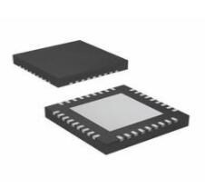
TDA7056B Package
The following figure is the Package of TDA7056B.

Package
TDA7056B Manufacturer
NXP Semiconductors N.V., headquartered in Eindhoven, Netherlands, is a Dutch multinational semiconductor manufacturer specializing in the automotive industry. The company employs about 31,000 people in over 35 locations, including 11,200 engineers in 33 countries.
Datasheet PDF
- Datasheets :
- PCN Packaging :
1.How to replace TDA7056 with TDA7056B?
Pin 5 is not the same. Don’t connect pin 5. When pin 3 is tuned to just right with the potentiometer, it can be used temporarily.
2.What kind of replacement for TDA7056B, can TDA7056A be used?
Yes, you can.
3.Why does the TDA7056B power amplifier board not sound when it is powered on? I removed the independent power amplifier board from the TV. There is a pre-amplifier. It will sound when it is removed but it will not sound when it is removed.
First rule out whether there is sound output from the pre-amplifier, and the next step is the integrated block. Except that the power supply is normal and the previous stage is okay, the integrated block should be broken.
![The Guide to TPS63060DSCR Buck-Boost Switching Regulator IC [FAQ]](https://res.utmel.com/Images/Article/7a961e0a-cdc6-4b9f-8463-ab8d34551a37.jpg) The Guide to TPS63060DSCR Buck-Boost Switching Regulator IC [FAQ]
The Guide to TPS63060DSCR Buck-Boost Switching Regulator IC [FAQ]22 March 20225673
 Designing with AD623: Datasheet, Pinout, and Medical/Transducer Interface Guide
05 February 2026192
 NXP S32K144 32-Bit ARM® Cortex®-M4F Microcontroller
22 May 20253143
 74HC132 Trigger: Circuit, Pinout, and Datasheet
18 December 20214384
 1N5408 Power Diode : Pinout, Price, Datasheet
27 July 20219909
 dsPIC33FJ64MC202EMM Microcontroller Datasheet Overview
29 February 2024155
 A General Introduction to TPS40140RHHT Synchronous Buck Controller
23 April 2022918
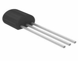 Transistor PN2222A Silicon NPN Audio Amplifier: Pinout, Datasheet, and Package
12 January 20224832
 Analyzing Temperature Parameters of Si, SiC and GaN Power Devices
09 September 20231555
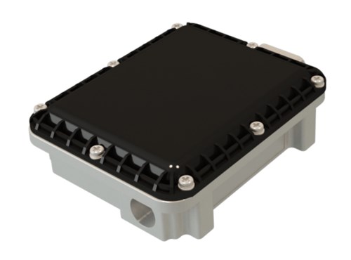 What is a Radar Sensor?
04 September 202011398
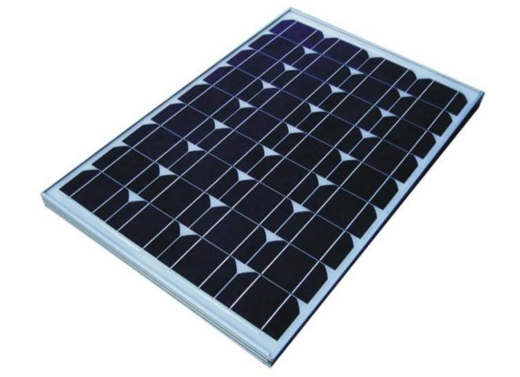 How do Solar Cells Work?
20 November 20203133
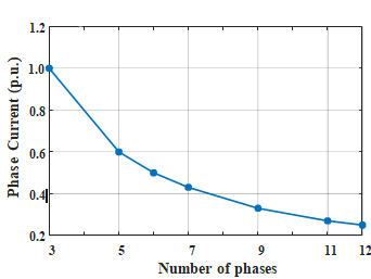 Revolutionizing Automotive Traction: A Comprehensive Review of Multiphase Drives for Next-Generation Vehicles
04 May 20234275
 Microchip FPGA Solutions: Aerospace and Industrial Applications
09 June 2025906
 AI Server Components: Engineering Next-Gen Data Center Hardware for 100kW Racks
15 May 2026421
 What is Smoke Detector?
26 October 20213776
 What is Keyboard and How to Choose It?
17 February 20226925
NXP USA Inc.
In Stock
United States
China
Canada
Japan
Russia
Germany
United Kingdom
Singapore
Italy
Hong Kong(China)
Taiwan(China)
France
Korea
Mexico
Netherlands
Malaysia
Austria
Spain
Switzerland
Poland
Thailand
Vietnam
India
United Arab Emirates
Afghanistan
Åland Islands
Albania
Algeria
American Samoa
Andorra
Angola
Anguilla
Antigua & Barbuda
Argentina
Armenia
Aruba
Australia
Azerbaijan
Bahamas
Bahrain
Bangladesh
Barbados
Belarus
Belgium
Belize
Benin
Bermuda
Bhutan
Bolivia
Bonaire, Sint Eustatius and Saba
Bosnia & Herzegovina
Botswana
Brazil
British Indian Ocean Territory
British Virgin Islands
Brunei
Bulgaria
Burkina Faso
Burundi
Cabo Verde
Cambodia
Cameroon
Cayman Islands
Central African Republic
Chad
Chile
Christmas Island
Cocos (Keeling) Islands
Colombia
Comoros
Congo
Congo (DRC)
Cook Islands
Costa Rica
Côte d’Ivoire
Croatia
Cuba
Curaçao
Cyprus
Czechia
Denmark
Djibouti
Dominica
Dominican Republic
Ecuador
Egypt
El Salvador
Equatorial Guinea
Eritrea
Estonia
Eswatini
Ethiopia
Falkland Islands
Faroe Islands
Fiji
Finland
French Guiana
French Polynesia
Gabon
Gambia
Georgia
Ghana
Gibraltar
Greece
Greenland
Grenada
Guadeloupe
Guam
Guatemala
Guernsey
Guinea
Guinea-Bissau
Guyana
Haiti
Honduras
Hungary
Iceland
Indonesia
Iran
Iraq
Ireland
Isle of Man
Israel
Jamaica
Jersey
Jordan
Kazakhstan
Kenya
Kiribati
Kosovo
Kuwait
Kyrgyzstan
Laos
Latvia
Lebanon
Lesotho
Liberia
Libya
Liechtenstein
Lithuania
Luxembourg
Macao(China)
Madagascar
Malawi
Maldives
Mali
Malta
Marshall Islands
Martinique
Mauritania
Mauritius
Mayotte
Micronesia
Moldova
Monaco
Mongolia
Montenegro
Montserrat
Morocco
Mozambique
Myanmar
Namibia
Nauru
Nepal
New Caledonia
New Zealand
Nicaragua
Niger
Nigeria
Niue
Norfolk Island
North Korea
North Macedonia
Northern Mariana Islands
Norway
Oman
Pakistan
Palau
Palestinian Authority
Panama
Papua New Guinea
Paraguay
Peru
Philippines
Pitcairn Islands
Portugal
Puerto Rico
Qatar
Réunion
Romania
Rwanda
Samoa
San Marino
São Tomé & Príncipe
Saudi Arabia
Senegal
Serbia
Seychelles
Sierra Leone
Sint Maarten
Slovakia
Slovenia
Solomon Islands
Somalia
South Africa
South Sudan
Sri Lanka
St Helena, Ascension, Tristan da Cunha
St. Barthélemy
St. Kitts & Nevis
St. Lucia
St. Martin
St. Pierre & Miquelon
St. Vincent & Grenadines
Sudan
Suriname
Svalbard & Jan Mayen
Sweden
Syria
Tajikistan
Tanzania
Timor-Leste
Togo
Tokelau
Tonga
Trinidad & Tobago
Tunisia
Turkey
Turkmenistan
Turks & Caicos Islands
Tuvalu
U.S. Outlying Islands
U.S. Virgin Islands
Uganda
Ukraine
Uruguay
Uzbekistan
Vanuatu
Vatican City
Venezuela
Wallis & Futuna
Yemen
Zambia
Zimbabwe
![TDA8950TH/N1,118]() TDA8950TH/N1,118
TDA8950TH/N1,118NXP USA Inc.
![TDA8920CTH/N1,118]() TDA8920CTH/N1,118
TDA8920CTH/N1,118NXP USA Inc.
![SA58631TK,115]() SA58631TK,115
SA58631TK,115NXP USA Inc.
![TDA8954TH/N1,118]() TDA8954TH/N1,118
TDA8954TH/N1,118NXP USA Inc.
![TFA9896UK/N1Z]() TFA9896UK/N1Z
TFA9896UK/N1ZNXP USA Inc.
![SA58672UK,027]() SA58672UK,027
SA58672UK,027NXP USA Inc.
![TDA8954J/N1,112]() TDA8954J/N1,112
TDA8954J/N1,112NXP USA Inc.
![TDA8541T/N1,118]() TDA8541T/N1,118
TDA8541T/N1,118NXP USA Inc.
![TDF8599ATH/N2CY]() TDF8599ATH/N2CY
TDF8599ATH/N2CYNXP USA Inc.
![TDA8954TH/N1,112]() TDA8954TH/N1,112
TDA8954TH/N1,112NXP USA Inc.


