
1N4003 Rectifier Diode: Pinout, Datasheet, and 1N4003 vs 1N4007

Standard Diode Rectifier Standard Recovery >500ns, > 200mA (Io) 1.1V @ 1A -55°C~175°C 5μA @ 200V 2-Termination Tape & Reel (TR) DO-204AL, DO-41, Axial Through Hole


Standard Diode Rectifier Standard Recovery >500ns, > 200mA (Io) 1.1V @ 1A -55°C~175°C 5μA @ 200V 2-Termination Tape & Reel (TR) DO-204AL, DO-41, Axial Through Hole
The 1N4003 is a general-purpose usage diode that belongs to the 1N400X series.

Diode 1N4000 Series | Blocking voltage 50v 1000V
1N4003 Description
The 1N4003 is a general-purpose usage diode that belongs to the 1N400X series. It is a polarized axial-leaded device with a silver band denoting the cathode end of the diode. The 1N4003 can handle up to 200V reverse voltage and up to 1A of continuous current with a surge peak of 30A. It is often used for reverse voltage protection on DC input circuits and in many power applications such as DC-DC converters.
1N4003 Pinout

1N4003 CAD Model
Symbol

Footprint

3D Model

1N4003 Marking Diagram

1N4003 Features
Package Type: DO-41
Max Repetitive Reverse Voltage: 200 V
Non-repetitive Max Reverse Voltage: 240 V
Forward Voltage: 1.1 V
Average Forward Current: 1 A
Non-repetitive Max Fwd Current: 30 A
Reverse current: 5 µA
Max Power Dissipation: 3 W
Storage & Operating temperature: -55 to +175 Centigrade
1N4003 Advantages
Low cost construction
Low forward voltage drop
Low reverse leakage
High forward surge current capability
High temperature soldering guaranteed 260℃ /10 seconds, 0.375”(9.5 mm) lead length at 5 lbs(2.3kg) tension
Specifications
- TypeParameter
- Mounting Type
The "Mounting Type" in electronic components refers to the method used to attach or connect a component to a circuit board or other substrate, such as through-hole, surface-mount, or panel mount.
Through Hole - Package / Case
refers to the protective housing that encases an electronic component, providing mechanical support, electrical connections, and thermal management.
DO-204AL, DO-41, Axial - Surface Mount
having leads that are designed to be soldered on the side of a circuit board that the body of the component is mounted on.
NO - Diode Element Material
The parameter "Diode Element Material" refers to the specific semiconductor material used in the construction of a diode. This material determines the electrical characteristics and performance of the diode, including its forward voltage drop, reverse breakdown voltage, and switching speed. Common diode element materials include silicon, germanium, and gallium arsenide, each offering different advantages for various applications. The choice of material impacts the diode's efficiency, thermal stability, and overall suitability for specific electronic circuits.
SILICON - Number of Elements1
- Power Dissipation (Max)3W
- Packaging
Semiconductor package is a carrier / shell used to contain and cover one or more semiconductor components or integrated circuits. The material of the shell can be metal, plastic, glass or ceramic.
Tape & Reel (TR) - Pbfree Code
The "Pbfree Code" parameter in electronic components refers to the code or marking used to indicate that the component is lead-free. Lead (Pb) is a toxic substance that has been widely used in electronic components for many years, but due to environmental concerns, there has been a shift towards lead-free alternatives. The Pbfree Code helps manufacturers and users easily identify components that do not contain lead, ensuring compliance with regulations and promoting environmentally friendly practices. It is important to pay attention to the Pbfree Code when selecting electronic components to ensure they meet the necessary requirements for lead-free applications.
yes - Part Status
Parts can have many statuses as they progress through the configuration, analysis, review, and approval stages.
Obsolete - Moisture Sensitivity Level (MSL)
Moisture Sensitivity Level (MSL) is a standardized rating that indicates the susceptibility of electronic components, particularly semiconductors, to moisture-induced damage during storage and the soldering process, defining the allowable exposure time to ambient conditions before they require special handling or baking to prevent failures
1 (Unlimited) - Number of Terminations2
- Additional Feature
Any Feature, including a modified Existing Feature, that is not an Existing Feature.
HIGH RELIABILITY - Terminal Form
Occurring at or forming the end of a series, succession, or the like; closing; concluding.
WIRE - Peak Reflow Temperature (Cel)
Peak Reflow Temperature (Cel) is a parameter that specifies the maximum temperature at which an electronic component can be exposed during the reflow soldering process. Reflow soldering is a common method used to attach electronic components to a circuit board. The Peak Reflow Temperature is crucial because it ensures that the component is not damaged or degraded during the soldering process. Exceeding the specified Peak Reflow Temperature can lead to issues such as component failure, reduced performance, or even permanent damage to the component. It is important for manufacturers and assemblers to adhere to the recommended Peak Reflow Temperature to ensure the reliability and functionality of the electronic components.
NOT SPECIFIED - Reach Compliance Code
Reach Compliance Code refers to a designation indicating that electronic components meet the requirements set by the Registration, Evaluation, Authorization, and Restriction of Chemicals (REACH) regulation in the European Union. It signifies that the manufacturer has assessed and managed the chemical substances within the components to ensure safety and environmental protection. This code is vital for compliance with regulations aimed at minimizing risks associated with hazardous substances in electronic products.
unknown - Time@Peak Reflow Temperature-Max (s)
Time@Peak Reflow Temperature-Max (s) refers to the maximum duration that an electronic component can be exposed to the peak reflow temperature during the soldering process, which is crucial for ensuring reliable solder joint formation without damaging the component.
NOT SPECIFIED - Pin Count
a count of all of the component leads (or pins)
2 - JESD-30 Code
JESD-30 Code refers to a standardized descriptive designation system established by JEDEC for semiconductor-device packages. This system provides a systematic method for generating designators that convey essential information about the package's physical characteristics, such as size and shape, which aids in component identification and selection. By using JESD-30 codes, manufacturers and engineers can ensure consistency and clarity in the specification of semiconductor packages across various applications and industries.
O-PALF-W2 - Qualification Status
An indicator of formal certification of qualifications.
COMMERCIAL - Configuration
The parameter "Configuration" in electronic components refers to the specific arrangement or setup of the components within a circuit or system. It encompasses how individual elements are interconnected and their physical layout. Configuration can affect the functionality, performance, and efficiency of the electronic system, and may influence factors such as signal flow, impedance, and power distribution. Understanding the configuration is essential for design, troubleshooting, and optimizing electronic devices.
SINGLE - Speed
In electronic components, "Speed" typically refers to the rate at which data can be processed or transferred within the component. It is a measure of how quickly the component can perform its functions, such as executing instructions or transmitting signals. Speed is often specified in terms of frequency, such as clock speed in processors or data transfer rate in memory modules. Higher speed components can perform tasks more quickly, leading to improved overall performance in electronic devices. It is an important parameter to consider when designing or selecting electronic components for specific applications.
Standard Recovery >500ns, > 200mA (Io) - Diode Type
In electronic components, the parameter "Diode Type" refers to the specific type or configuration of a diode, which is a semiconductor device that allows current to flow in one direction only. There are various types of diodes, each designed for specific applications and functions. Common diode types include rectifier diodes, zener diodes, light-emitting diodes (LEDs), and Schottky diodes, among others. The diode type determines the diode's characteristics, such as forward voltage drop, reverse breakdown voltage, and maximum current rating, making it crucial for selecting the right diode for a particular circuit or application. Understanding the diode type is essential for ensuring proper functionality and performance in electronic circuits.
Standard - Current - Reverse Leakage @ Vr
Current - Reverse Leakage @ Vr is a parameter that describes the amount of current that flows in the reverse direction through a diode or other semiconductor component when a reverse voltage (Vr) is applied across it. This leakage current is typically very small, but it is important to consider in electronic circuits as it can affect the overall performance and reliability of the component. The reverse leakage current is influenced by factors such as the material properties of the semiconductor, temperature, and the magnitude of the reverse voltage applied. Manufacturers provide this parameter in datasheets to help engineers and designers understand the behavior of the component in reverse bias conditions.
5μA @ 200V - Voltage - Forward (Vf) (Max) @ If
The parameter "Voltage - Forward (Vf) (Max) @ If" refers to the maximum voltage drop across a diode when it is forward-biased and conducting a specified forward current (If). It indicates the maximum potential difference the diode can withstand while allowing current to flow in the forward direction without breaking down. This value is crucial for designing circuits as it helps determine how much voltage will be lost across the diode during operation. Higher Vf values can lead to reduced efficiency in power applications, making this parameter essential for optimizing circuit performance.
1.1V @ 1A - Case Connection
Case Connection refers to the method by which an electronic component's case or housing is connected to the electrical circuit. This connection is important for grounding purposes, mechanical stability, and heat dissipation. The case connection can vary depending on the type of component and its intended application. It is crucial to ensure a secure and reliable case connection to maintain the overall performance and safety of the electronic device.
ISOLATED - Operating Temperature - Junction
Operating Temperature - Junction refers to the maximum temperature at which the junction of an electronic component can safely operate without causing damage or performance degradation. This parameter is crucial for determining the reliability and longevity of the component, as excessive heat can lead to thermal stress and failure. Manufacturers specify the operating temperature range to ensure that the component functions within safe limits under normal operating conditions. It is important for designers and engineers to consider the operating temperature - junction when selecting and using electronic components to prevent overheating and ensure optimal performance.
-55°C~175°C - Output Current-Max
Output Current-Max is a parameter in electronic components that specifies the maximum amount of current that can be safely drawn from the output of the component without causing damage. It is an important specification to consider when designing circuits to ensure that the component can handle the required current without overheating or failing. Exceeding the maximum output current can lead to performance issues, component damage, or even complete failure of the circuit. It is crucial to adhere to the specified maximum output current to ensure the reliable operation of the electronic component and the overall circuit.
1A - Voltage - DC Reverse (Vr) (Max)
Voltage - DC Reverse (Vr) (Max) is a parameter in electronic components that specifies the maximum reverse voltage that the component can withstand without breaking down. This parameter is crucial for components like diodes and transistors that are often subjected to reverse voltage during operation. Exceeding the maximum reverse voltage can lead to the component failing or getting damaged. Designers need to consider this parameter when selecting components to ensure the reliability and longevity of their circuits.
200V - Current - Average Rectified (Io)
The parameter "Current - Average Rectified (Io)" in electronic components refers to the average value of the rectified current flowing through the component. This parameter is important in determining the average power dissipation and thermal considerations of the component. It is typically specified in datasheets for diodes, rectifiers, and other components that handle alternating current (AC) and convert it to direct current (DC). Understanding the average rectified current helps in selecting the appropriate component for a given application to ensure reliable operation and prevent overheating.
1A - Rep Pk Reverse Voltage-Max
Rep Pk Reverse Voltage-Max refers to the maximum reverse voltage that an electronic component, such as a diode, can withstand during a specified period of time without failing. This parameter is crucial in determining the safe operating limits of components in circuits where reverse voltage conditions may occur. Exceeding this value can lead to breakdown or permanent damage to the component. It is typically expressed in volts and is a key specification in signal and power applications.
200V - Capacitance @ Vr, F
Capacitance @ Vr, F refers to the capacitance value of a capacitor measured at a specified rated voltage (Vr). It indicates how much electrical charge the capacitor can store per volt when subjected to this voltage. This parameter is essential for understanding the behavior of capacitors in circuits, particularly under different voltage conditions, and ensures that the component operates within its safe limits. The unit of measurement is Farads (F), which quantifies the capacitor's ability to hold an electrical charge.
15pF @ 4V 1MHz - RoHS Status
RoHS means “Restriction of Certain Hazardous Substances” in the “Hazardous Substances Directive” in electrical and electronic equipment.
ROHS3 Compliant
1N4003 Functional Alternatives

1N4003 Equivalents
1N4002, 1N4004, 1N4005, 1N4006, 1N4007, 1N4148, 1N4733A, 1N4934, 1N4935, 1N5408, 1N5822, SF12, RL202, RL203, HER102, HER103, HER202, HER203, FR202, FR203, Zener Diodes
Please check their parameters and pin configuration before replacing them in your circuit.
Where to use 1N4003
The 1N4003 diode can be used in many general-purpose applications. It can be used to build a bridge rectifier, an essential part of a DC power supply that converts AC to DC. It can also be used in clippers applications, reverse current blocking in various circuits to protect components, and logic gates, etc.
1N4003 vs 1N4007
The 1N4003 and the 1N4007 are almost identical except for their peak reverse voltage ratings. The 1N4007 can withstand a higher reverse voltage at 1000 V (the highest among the 1N400X series) which is useful in most circuits. The 1N4003 has a much lower reverse voltage which is at 200 V. But to be used in a circuit with a reverse voltage within the 200 V limit, you can surely use the 1N4003 instead of the 1N4007.
1N4003 Applications
Power Supply Rectifiers
Half Wave and Full Wave Rectifiers
Battery Chargers Circuits
Adapter Circuits
Inverters
AC to DC Converters
Components Protection
Voltage Blocking
Current Flow Regulators
Freewheeling Diodes Application
1N4003 Package

1N4003 Package & Dimensions
1N4003 Manufacturer
Rochester Electronics is the largest continuing source manufacturer of semiconductors in the world. With product licensing from leading manufacturers such as Analog Devices, Altera, Cypress, Fairchild, Freescale, Infineon, Intel, NXP, Renesas, and Texas Instruments, Rochester continues to manufacture and distribute mature products. For industrial, transportation, and hi-reliability markets, product life extension is critical for long-term production and maintenance. With over 100,000 products and 15 billion units in stock, no other company compares to our selection, capabilities, or solutions.
Trend Analysis
Datasheet PDF
- Datasheets :
1.What is 1N4003?
The 1N4003 is a general-purpose silicon Rectifier Diode, designed for low power and switching applications.
2.How to safely long run 1N4003 in a circuit?
To increase the usage life of 1N4003 diode it is suggested to not drive a load of more than 200V, do not drive more than 1A or 1000mA load, and always store or use the diode in temperature between -55 degrees centigrade to +175 degrees centigrade.
3.What is the difference between 1N4003 and 1N4007?
The main difference is the peak reverse voltage rating (there are other somewhat subtle differences). If you are absolutely certain that more than 200 VDC reverse bias is impossible in the circuit you can almost certainly use a 1N4003. The peak reverse voltage of 1N4007 is 1000 V.
 ADG1419 iCMOS SPDT Switch: Pinout, Features and Datasheet
15 February 20222381
 MC68HC705C8ACFNE: Trusted Sourcing Guide for Microcontroller Components
07 June 2025198
 93C46 EEPROM: Features, Pinout, and Datasheet
17 January 202210726
 A Beginner’s Guide to Using STM32F767ZIT6 in Industrial and Medical Projects
24 July 2025195
 1N4148W-7-F Switching Diode: Features, Pinout, and Datasheet
23 April 2022588
 STM32G030C8T6 MCU: Pinout, Applications and Datasheet
26 October 20233772
 PCA9555 CMOS Device: Datasheet, Pinout, Application Circuit
21 October 20214581
 BAT54S Diode: BAT54S Datasheet, Price, Pinout
27 January 20223654
 What is Field Programmable Gate Array?
29 September 20203444
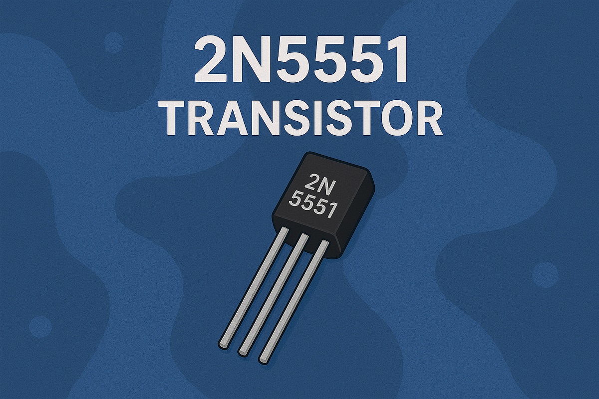 A Beginner's Guide to the 2N5551 Transistor and Its Uses
27 May 20251875
 What is Cloud Storage?
07 October 20211763
 Photoresistor Basics: Types, Principles and Applications
16 October 202541991
 A Selection of the Most Representative Charts——Artificial Intelligence Index Report
18 March 2022739
 Latest MLPerf Results: NVIDIA H100 GPUs Ride to the Top
13 September 20222511
 Photonic Integrated Circuits: Overcoming Challenges in Silicon Photonics
26 August 20242340
 FPGA vs ASIC: Comprehensive Comparison Guide
09 May 20256325
Rochester Electronics, LLC
In Stock
United States
China
Canada
Japan
Russia
Germany
United Kingdom
Singapore
Italy
Hong Kong(China)
Taiwan(China)
France
Korea
Mexico
Netherlands
Malaysia
Austria
Spain
Switzerland
Poland
Thailand
Vietnam
India
United Arab Emirates
Afghanistan
Åland Islands
Albania
Algeria
American Samoa
Andorra
Angola
Anguilla
Antigua & Barbuda
Argentina
Armenia
Aruba
Australia
Azerbaijan
Bahamas
Bahrain
Bangladesh
Barbados
Belarus
Belgium
Belize
Benin
Bermuda
Bhutan
Bolivia
Bonaire, Sint Eustatius and Saba
Bosnia & Herzegovina
Botswana
Brazil
British Indian Ocean Territory
British Virgin Islands
Brunei
Bulgaria
Burkina Faso
Burundi
Cabo Verde
Cambodia
Cameroon
Cayman Islands
Central African Republic
Chad
Chile
Christmas Island
Cocos (Keeling) Islands
Colombia
Comoros
Congo
Congo (DRC)
Cook Islands
Costa Rica
Côte d’Ivoire
Croatia
Cuba
Curaçao
Cyprus
Czechia
Denmark
Djibouti
Dominica
Dominican Republic
Ecuador
Egypt
El Salvador
Equatorial Guinea
Eritrea
Estonia
Eswatini
Ethiopia
Falkland Islands
Faroe Islands
Fiji
Finland
French Guiana
French Polynesia
Gabon
Gambia
Georgia
Ghana
Gibraltar
Greece
Greenland
Grenada
Guadeloupe
Guam
Guatemala
Guernsey
Guinea
Guinea-Bissau
Guyana
Haiti
Honduras
Hungary
Iceland
Indonesia
Iran
Iraq
Ireland
Isle of Man
Israel
Jamaica
Jersey
Jordan
Kazakhstan
Kenya
Kiribati
Kosovo
Kuwait
Kyrgyzstan
Laos
Latvia
Lebanon
Lesotho
Liberia
Libya
Liechtenstein
Lithuania
Luxembourg
Macao(China)
Madagascar
Malawi
Maldives
Mali
Malta
Marshall Islands
Martinique
Mauritania
Mauritius
Mayotte
Micronesia
Moldova
Monaco
Mongolia
Montenegro
Montserrat
Morocco
Mozambique
Myanmar
Namibia
Nauru
Nepal
New Caledonia
New Zealand
Nicaragua
Niger
Nigeria
Niue
Norfolk Island
North Korea
North Macedonia
Northern Mariana Islands
Norway
Oman
Pakistan
Palau
Palestinian Authority
Panama
Papua New Guinea
Paraguay
Peru
Philippines
Pitcairn Islands
Portugal
Puerto Rico
Qatar
Réunion
Romania
Rwanda
Samoa
San Marino
São Tomé & Príncipe
Saudi Arabia
Senegal
Serbia
Seychelles
Sierra Leone
Sint Maarten
Slovakia
Slovenia
Solomon Islands
Somalia
South Africa
South Sudan
Sri Lanka
St Helena, Ascension, Tristan da Cunha
St. Barthélemy
St. Kitts & Nevis
St. Lucia
St. Martin
St. Pierre & Miquelon
St. Vincent & Grenadines
Sudan
Suriname
Svalbard & Jan Mayen
Sweden
Syria
Tajikistan
Tanzania
Timor-Leste
Togo
Tokelau
Tonga
Trinidad & Tobago
Tunisia
Turkey
Turkmenistan
Turks & Caicos Islands
Tuvalu
U.S. Outlying Islands
U.S. Virgin Islands
Uganda
Ukraine
Uruguay
Uzbekistan
Vanuatu
Vatican City
Venezuela
Wallis & Futuna
Yemen
Zambia
Zimbabwe
![1N4150]() 1N4150
1N4150Rochester Electronics
![MBRS130L]() MBRS130L
MBRS130LRochester Electronics
![MURD320T4G]() MURD320T4G
MURD320T4GRochester Electronics
![GBPC3508]() GBPC3508
GBPC3508Rochester Electronics
![1N4305]() 1N4305
1N4305Rochester Electronics, LLC
![RB521S30T1]() RB521S30T1
RB521S30T1Rochester Electronics, LLC
![1N5404]() 1N5404
1N5404Rochester Electronics
![BAT64-05WE6327]() BAT64-05WE6327
BAT64-05WE6327Rochester Electronics
![BAS70-02LE6327]() BAS70-02LE6327
BAS70-02LE6327Rochester Electronics
![1N3595JTX]() 1N3595JTX
1N3595JTXRochester Electronics


