
 Product
 Brand
Brand Articles
 Tools
Tools
A Practical Guide to STM32F429IIT6 in Embedded Systems

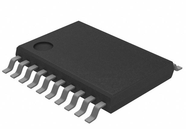
2MB 2M x 8 FLASH ARM® Cortex®-M4 32-Bit Microcontroller STM32F4 Series STM32F429 176 Pin 180MHz 3.3V 176-LQFP


2MB 2M x 8 FLASH ARM® Cortex®-M4 32-Bit Microcontroller STM32F4 Series STM32F429 176 Pin 180MHz 3.3V 176-LQFP
Discover how STM32F429IIT6 enhances embedded systems with ARM Cortex-M4, advanced graphics, connectivity, and low-power modes for versatile applications.
Product Introduction
The STM32F429IIT6 microcontroller offers advanced capabilities for embedded systems. It enables you to build high-performance applications with its powerful ARM Cortex-M4 core. This microcontroller stands out due to its versatility in handling complex tasks, such as managing peripherals or supporting graphic displays. Its robust design makes it suitable for modern systems that require reliability and efficiency. Whether you aim to create interactive interfaces or control automation processes, the STM32F429IIT6 provides the tools you need to succeed.
Key Features of the STM32F429IIT6
ARM Cortex-M4 Core and Performance
The STM32F429IIT6 microcontroller is powered by the ARM Cortex-M4 core, which delivers exceptional performance for embedded systems. Running at a clock speed of 180 MHz, this core achieves up to 225 DMIPS (Dhrystone Million Instructions Per Second), making it ideal for applications requiring high computational power.
You’ll benefit from its integrated single-precision Floating Point Unit (FPU, which accelerates mathematical computations). This feature is particularly useful for tasks like signal processing, control algorithms, and real-time data analysis. The ARM Cortex-M4 core also supports advanced interrupt handling, ensuring responsive and efficient system performance.
Tip: Use the STM32F429IIT6 for applications that demand real-time processing, such as motor control or robotics. Its ARM Cortex-M4 core ensures reliable and fast execution.
Memory and Peripheral Capabilities
The STM32F429IIT6 offers robust memory and peripheral capabilities, enabling you to design versatile and feature-rich embedded systems. It includes 2 MB of dual-bank Flash memory for program storage and 256 KB of SRAM for data handling. Additionally, it provides 64 KB of Core Coupled Memory (CCM) and 4 KB of Backup SRAM for specialized tasks.
Memory and Peripheral Specifications:
| Parameter | Details |
|---|---|
| Program Memory Size | 2MB (2M x 8) |
| RAM Size | 256K x 8 |
| Peripherals | Brown-out Detect/Reset, DMA, I2S, LCD, POR, PWM, WDT |
| Data Converters | A/D 24x12b; D/A 2x12b |
The microcontroller integrates advanced peripherals, including three 12-bit ADCs, two 12-bit DACs, and fourteen timers. These features allow you to implement precise data acquisition, signal generation, and timing control. Communication interfaces like USART, UART, I²C, SPI, and USB OTG provide seamless connectivity options for external devices.
Note: The STM32F429IIT6’s rich peripheral set makes it suitable for applications like industrial automation and IoT devices.
Advanced Graphics and Display Support
The STM32F429IIT6 stands out with its advanced graphics capabilities, making it perfect for Human-Machine Interface (HMI) applications. It features a built-in LCD-TFT controller that supports high-resolution displays. You can create visually appealing interfaces with ease, thanks to its hardware acceleration for graphical operations.
The microcontroller also includes Chrom-ART Accelerator™, which enhances graphical performance by offloading tasks from the CPU. This feature reduces rendering time and improves the responsiveness of your display. Whether you’re designing dashboards, touchscreens, or interactive panels, the STM32F429IIT6 provides the tools to bring your vision to life.
Tip: Pair the STM32F429IIT6 with a compatible display module to unlock its full graphical potential.
Connectivity and USB OTG Features
The STM32F429IIT6 microcontroller excels in connectivity, offering a wide range of communication protocols to meet diverse application needs. Whether you’re designing IoT devices, industrial systems, or consumer electronics, this microcontroller provides the tools to connect seamlessly with other devices and networks.
USB OTG Capabilities
The STM32F429IIT6 supports USB On-The-Go (OTG), enabling it to function as both a host and a device. This feature enhances versatility, allowing you to connect peripherals like keyboards, mice, or storage devices directly to your system. The microcontroller supports both Full-Speed and High-Speed USB modes, ensuring fast and reliable data transfer.
Tip: Use USB OTG for applications requiring dynamic device roles, such as portable data acquisition systems or multimedia players.
Communication Protocols
The STM32F429IIT6 integrates multiple communication interfaces, making it suitable for complex systems requiring diverse connectivity options. These include:
CANbus: Ideal for automotive and industrial applications.
Ethernet: Enables high-speed network communication.
SPI and I²C: Facilitates communication with sensors and other peripherals.
UART/USART: Provides reliable serial communication for debugging or data exchange.
IrDA and LINbus: Supports infrared and automotive communication standards.
Connectivity Features Overview
| Feature | Description |
|---|---|
| USB OTG | Supports both Full-Speed and High-Speed modes, enhancing versatility in connectivity options. |
| Multiple Protocols | Integrates USARTs, UARTs, I²C, SPI, CAN, and more, facilitating diverse communication needs. |
The STM32F429IIT6’s connectivity features make it a powerful choice for applications like IoT gateways, industrial controllers, and smart home devices.
Power Efficiency and Low-Power Modes
Power efficiency is a critical factor in embedded systems, especially for battery-operated devices. The STM32F429IIT6 microcontroller addresses this need with its advanced low-power modes and energy-saving features.
Low-Power Modes
The STM32F429IIT6 offers multiple low-power modes, including Sleep, Stop, and Standby. These modes allow you to reduce power consumption significantly while maintaining essential system functions. For example:
Sleep Mode: Keeps the CPU inactive while peripherals remain operational.
Stop Mode: Disables most clocks, reducing power usage while retaining SRAM and register contents.
Standby Mode: Minimizes power consumption by shutting down all clocks and retaining only essential data in Backup SRAM.
Note: Use Standby Mode for applications requiring extended battery life, such as remote sensors or wearable devices.
Energy-Saving Features
The STM32F429IIT6 includes additional features to optimize power efficiency:
Dynamic Voltage Scaling: Adjusts the operating voltage based on workload, reducing energy consumption during low-demand periods.
RTC (Real-Time Clock): Operates independently of the main system, enabling timekeeping with minimal power usage.
Backup Domain: Retains critical data even during power loss, ensuring system reliability.
These features make the STM32F429IIT6 an excellent choice for energy-conscious applications, such as portable medical devices or solar-powered systems.
Setting Up the STM32F429 Discovery Kit
Understanding the Hardware Components
Before you begin working with the stm32f429 discovery kit, it’s essential to familiarize yourself with its hardware components. This kit includes a range of features designed to help you explore the microcontroller’s capabilities. The main component is the STM32F429ZIT6 microcontroller, which serves as the brain of the system. It also includes an onboard LCD-TFT display, LEDs, push buttons, and various connectors for peripherals.
To better understand the hardware, refer to the following technical resources:
| Type | Description |
|---|---|
| STM32F429ZIT6 Pinout | Detailed pin configuration for the microcontroller |
| STM32F429ZIT6 CAD Model | Includes symbol, footprint, and 3D model |
| STM32F429ZIT6 Block Diagram | Visual representation of the microcontroller's architecture |
| STM32F429ZIT6 Power Supply Scheme | Diagram showing power supply connections and requirements |
These resources provide a clear picture of how the components interact. For example, the block diagram helps you understand the architecture, while the pinout shows how to connect external devices.
Tip: Keep the pinout and power supply scheme handy when connecting peripherals to avoid errors.
Power Supply and Peripheral Connections
The stm32f429 discovery kit requires a stable power supply to function correctly. You can power the kit using a USB cable connected to your computer or an external power source. Ensure the voltage matches the kit’s requirements to prevent damage.
For peripheral connections, the kit offers multiple options. Use the GPIO pins to connect sensors, actuators, or other devices. The onboard connectors support communication protocols like SPI, I²C, and UART, making it easy to integrate additional hardware.
Note: Double-check the polarity and voltage of your connections to avoid damaging the microcontroller or peripherals.
Installing Drivers and Development Tools
To start programming the stm32f429 discovery kit, you need to install the necessary drivers and development tools. Begin by downloading the STM32CubeIDE, an integrated development environment that simplifies coding and debugging. You’ll also need the STM32CubeMX software to configure the microcontroller’s settings.
Once you’ve installed the tools, connect the kit to your computer using a USB cable. The system should automatically detect the device and install the required drivers. If it doesn’t, download the drivers from STMicroelectronics’ official website.
After installation, open STM32CubeMX and create a new project. Select the STM32F429ZIT6 microcontroller and configure its peripherals based on your application. This step ensures the microcontroller is ready for programming.
Tip: Run a simple test program, like blinking an LED, to verify that the setup works correctly.
Running a Test Program for Verification
After setting up your STM32F429 Discovery Kit, running a test program ensures everything works as expected. A simple LED blinking program is a great starting point. It helps you verify the microcontroller, power supply, and connections.
Steps to Run the Test Program
Open STM32CubeMX
Launch the STM32CubeMX software. Create a new project and select the STM32F429ZIT6 microcontroller. Configure the GPIO pin connected to the onboard LED as an output.Generate the Code
Click on the "Generate Code" button. This action creates a project compatible with your chosen Integrated Development Environment (IDE), such as STM32CubeIDE.Write the LED Blinking Code
Open the generated project in STM32CubeIDE. Add the following code snippet inside thewhile(1)loop in themain.cfile:HAL_GPIO_TogglePin(GPIOG, GPIO_PIN_13); // Toggle LED HAL_Delay(500); // Delay for 500ms
This code toggles the LED state every 500 milliseconds.
Compile and Upload the Program
Build the project to compile the code. Connect your Discovery Kit to the computer using a USB cable. Use the "Debug" or "Run" option in STM32CubeIDE to upload the firmware to the microcontroller.Observe the Results
Once the program runs, the onboard LED should blink at a steady interval. If it doesn’t, double-check your configurations and connections.
Tip: If you encounter issues, verify that the correct GPIO pin is configured and the microcontroller is powered properly.
Running this test program confirms that your STM32F429 Discovery Kit is ready for more complex projects. It also familiarizes you with the development tools and workflow.
Programming the STM32F429 Microcontroller
Selecting an IDE and Setting Up STM32CubeMX
To program the STM32F429 microcontroller, you need the right tools. Start by selecting an Integrated Development Environment (IDE). STM32CubeIDE is a popular choice because it combines code editing, debugging, and project management in one platform. It’s free and specifically designed for STM32 microcontrollers, making it an excellent option for beginners and professionals alike.
Once you’ve installed STM32CubeIDE, download STM32CubeMX. This tool simplifies the configuration process by providing a graphical interface to set up the microcontroller’s peripherals. It also generates initialization code, saving you time and reducing errors.
Steps to Set Up STM32CubeMX:
Open STM32CubeMX and create a new project.
Select the STM32F429 microcontroller from the list of available devices.
Configure the peripherals you plan to use, such as GPIO, UART, or ADC.
Set the clock tree to ensure the microcontroller operates at the desired frequency (up to 180 MHz for the STM32F429).
Generate the initialization code and open it in STM32CubeIDE.
Tip: Use the graphical pinout view in STM32CubeMX to assign functions to specific pins. This feature helps you avoid conflicts and ensures proper hardware configuration.
Configuring the Microcontroller and Writing Code
After setting up the tools, it’s time to configure the microcontroller and write your first program. The STM32F429 offers a wide range of peripherals, so you can tailor its configuration to suit your application.
Configuration Process:
Clock Settings: Use STM32CubeMX to configure the system clock. The STM32F429 operates at up to 180 MHz, delivering up to 225 DMIPS and scoring 608 CoreMark when executing from flash memory. These benchmarks highlight its exceptional performance for demanding applications.
Peripheral Initialization: Enable and configure the peripherals you need. For example, set up GPIO pins as inputs or outputs, initialize UART for serial communication, or configure ADC for analog-to-digital conversion.
Interrupts: Enable interrupts for peripherals that require real-time responsiveness. The ARM Cortex-M4 core supports advanced interrupt handling, ensuring efficient performance.
Once the configuration is complete, STM32CubeMX generates the initialization code. Open this code in STM32CubeIDE and add your application logic. For example, you can write a program to read sensor data and send it over UART.
// Example: Reading ADC value and sending it via UART
uint32_t adcValue = 0;
char message[50];

while (1) {
    adcValue = HAL_ADC_GetValue(&hadc1); // Read ADC value
    sprintf(message, "ADC Value: %lu\r\n", adcValue);
    HAL_UART_Transmit(&huart1, (uint8_t*)message, strlen(message), HAL_MAX_DELAY); // Send via UART
    HAL_Delay(1000); // Wait for 1 second
}Note: Always test your configuration with a simple program before moving on to complex applications. This approach helps you identify and fix issues early.
Compiling, Debugging, and Uploading Firmware
Once you’ve written your code, the next step is to compile, debug, and upload it to the microcontroller. STM32CubeIDE simplifies this process with its integrated tools.
Steps to Compile and Upload Firmware:
Compile the Code: Click the "Build" button in STM32CubeIDE to compile your project. The IDE checks for errors and generates the firmware file.
Connect the Microcontroller: Use a USB cable to connect the STM32F429 Discovery Kit to your computer. Ensure the kit is powered and recognized by the IDE.
Upload the Firmware: Click the "Debug" or "Run" button in STM32CubeIDE. The IDE flashes the firmware to the microcontroller using the SWD (Serial Wire Debug) interface. SWD is fast and reliable, making it ideal for development.
Debugging Tips:
Use breakpoints to pause the program and inspect variables.
Check the peripheral registers in the IDE to verify their configuration.
Monitor the microcontroller’s behavior using the live expression view.
Tip: If the microcontroller doesn’t respond as expected, double-check the clock settings and peripheral configurations. These are common sources of issues.
For advanced users, the STM32F429 also supports USB DFU (Device Firmware Upgrade) mode. This feature allows you to flash the firmware without additional hardware, depending on the state of the BOOTx pins upon reset. While not essential for development, it can be useful in specific scenarios.
By following these steps, you can efficiently program, debug, and deploy applications on the STM32F429 microcontroller. Hands-on experimentation is key to mastering its features and unlocking its full potential.
Best Practices for Efficient Programming
Efficient programming is essential when working with the STM32F429 microcontroller. By following proven strategies, you can save time, reduce errors, and create reliable applications. Here are some best practices to help you get the most out of your development process:
1. Plan Your Project Before Coding
Start by outlining your project’s goals and requirements. Identify the peripherals you’ll use and the features your application needs. Create a flowchart or diagram to visualize the system’s functionality.
Tip: Use STM32CubeMX to map out your microcontroller’s configuration. This tool simplifies planning and ensures you don’t overlook critical settings.
2. Keep Your Code Modular
Write your code in small, reusable functions. Modular programming makes your code easier to read, debug, and maintain. For example, instead of writing all logic in the main() function, create separate functions for tasks like sensor reading, data processing, and communication.
void ReadSensorData() {
    // Code to read sensor data
}

void ProcessData() {
    // Code to process data
}

void SendData() {
    // Code to send data via UART
}Note: Modular code allows you to test individual functions independently, making debugging faster and more effective.
3. Use Descriptive Names for Variables and Functions
Choose clear and meaningful names for your variables, functions, and constants. Avoid generic names like temp or data. Instead, use names that describe their purpose, such as temperatureSensorValue or sendUARTMessage().
Tip: Consistent naming conventions improve readability and help you understand your code months or years later.
4. Leverage Interrupts for Real-Time Tasks
The STM32F429 microcontroller supports advanced interrupt handling. Use interrupts for tasks that require immediate attention, such as responding to a button press or handling communication events.
void HAL_GPIO_EXTI_Callback(uint16_t GPIO_Pin) {
    if (GPIO_Pin == GPIO_PIN_0) {
        // Code to handle button press
    }
}Alert: Avoid using long or complex code inside interrupt service routines (ISRs). Keep ISRs short to maintain system responsiveness.
5. Optimize Memory Usage
Efficient memory management is crucial for embedded systems. Use global variables sparingly and prefer local variables whenever possible. Monitor your stack and heap usage to prevent memory overflow.
| Memory Optimization Tips | Description |
|---|---|
| Use Local Variables | Reduces memory usage and improves performance. |
| Avoid Large Arrays | Use dynamic allocation for large data structures. |
| Monitor SRAM Usage | Check memory consumption regularly during debugging. |
Note: Use STM32CubeIDE’s memory analyzer to track memory usage and identify potential issues.
6. Test Incrementally
Test your code in small increments. After adding a new feature, verify its functionality before moving on to the next task. This approach helps you catch errors early and prevents them from compounding.
Tip: Start with simple programs, like blinking an LED, and gradually build up to more complex applications.
7. Document Your Code
Write comments to explain the purpose of your code. Include details about function inputs, outputs, and expected behavior. Well-documented code helps you and others understand the logic behind your implementation.
// Function to read temperature sensor data
// Returns the temperature value in Celsius
float ReadTemperatureSensor() {
    // Code to read sensor data
}Reminder: Avoid over-commenting. Focus on explaining complex or non-obvious parts of your code.
8. Use Debugging Tools Effectively
STM32CubeIDE offers powerful debugging tools. Use breakpoints to pause execution and inspect variables. Monitor peripheral registers to verify their configuration.
Tip: Enable live expression monitoring to track variable values in real-time during debugging.
9. Follow Coding Standards
Adopt a consistent coding style and follow industry standards. Use proper indentation, spacing, and formatting to make your code visually appealing and easy to read.
Alert: Inconsistent formatting can lead to confusion and errors, especially in collaborative projects.
10. Stay Updated with STM32 Resources
STMicroelectronics regularly updates its tools and libraries. Check their official website for the latest firmware, drivers, and documentation. Staying updated ensures compatibility and access to new features.
Tip: Join STM32 developer forums to learn from others and share your experiences.
By applying these best practices, you can streamline your programming workflow and create efficient, reliable applications with the STM32F429 microcontroller. Experiment with these strategies and adapt them to your specific needs.
Applications of the STM32F429IIT6
Real-Time Data Acquisition Systems
The STM32F429IIT6 microcontroller excels in real-time data acquisition systems. Its ARM Cortex-M4 core processes data quickly, making it ideal for applications that require immediate responses. You can use its high-speed ADCs to capture analog signals from sensors. These ADCs convert the signals into digital data for further analysis.
The microcontroller’s DMA (Direct Memory Access) feature enhances efficiency. It transfers data directly between peripherals and memory without involving the CPU. This reduces latency and ensures smooth operation. For example, you can design systems to monitor temperature, pressure, or vibration in industrial environments.
Tip: Use the STM32F429IIT6 for applications where accuracy and speed are critical, such as medical devices or environmental monitoring systems.
Human-Machine Interface (HMI) Development
The STM32F429IIT6 is a powerful tool for creating Human-Machine Interfaces (HMIs). Its LCD-TFT controller supports high-resolution displays, allowing you to design interactive dashboards and touchscreens. The Chrom-ART Accelerator™ boosts graphical performance, making animations and transitions smooth.
You can pair the microcontroller with a touchscreen module to build user-friendly interfaces. These interfaces can control machines, appliances, or vehicles. The STM32F429IIT6’s rich peripheral set simplifies the integration of buttons, sliders, and other input devices.
Note: The STM32F429IIT6 is perfect for embedded applications that require intuitive user interfaces, such as smart home systems or industrial control panels.
IoT Devices and Connectivity Solutions
The STM32F429IIT6 offers extensive connectivity options, making it ideal for IoT devices. Its USB OTG feature allows dynamic device roles, while Ethernet and CANbus enable network communication. You can use its SPI and I²C interfaces to connect sensors and actuators.
The microcontroller’s low-power modes ensure energy efficiency, which is essential for battery-operated IoT devices. You can design smart devices that collect data, process it locally, and send it to the cloud. Examples include smart meters, wearable health trackers, and home automation systems.
Alert: The STM32F429IIT6’s connectivity features make it a strong choice for applications requiring reliable communication and low power consumption.
Motor Control and Automation Projects
The stm32f429iit6 microcontroller is an excellent choice for motor control and automation projects. Its advanced features and high processing power allow you to design systems that are both efficient and reliable. Whether you are working on industrial automation or robotics, this microcontroller provides the tools you need to succeed.
One of the key features of the stm32f429iit6 is its ability to handle precise motor control. It includes multiple timers that support Pulse Width Modulation (PWM). PWM is essential for controlling motor speed and direction. For example, you can use it to adjust the speed of a DC motor or control the position of a servo motor. The microcontroller’s high-resolution timers ensure smooth and accurate operation.
The stm32f429iit6 also supports advanced communication protocols like CANbus and Ethernet. These protocols are critical for automation systems that require real-time communication between devices. For instance, you can use CANbus to connect multiple motors in an industrial setup. Ethernet allows you to monitor and control your system remotely, adding flexibility to your design.
Another advantage of the stm32f429iit6 is its ability to process complex algorithms quickly. This capability is crucial for applications like robotic arms or automated conveyor belts. You can implement control algorithms such as PID (Proportional-Integral-Derivative) to achieve precise movement and stability.
Tip: Use the stm32f429iit6’s DMA feature to offload data transfer tasks from the CPU. This improves efficiency and ensures your motor control system operates smoothly.
By leveraging the stm32f429iit6, you can create robust motor control and automation solutions. Its combination of performance, connectivity, and flexibility makes it a powerful tool for modern embedded systems.
Troubleshooting the STM32F429IIT6
Resolving Driver and Connectivity Issues
Driver and connectivity problems can disrupt your embedded systems. To resolve these, start by ensuring that the correct drivers are installed. Visit the official STMicroelectronics website to download the latest drivers for your STM32F429 Discovery Kit. After installation, verify that your computer recognizes the microcontroller.
If the device is not detected, check the USB cable and port. Use a different cable or port to rule out hardware issues. For connectivity problems with peripherals, confirm that the connections match the pinout diagram. Misaligned or loose connections often cause communication failures.
Tip: Use a multimeter to test the continuity of your connections. This helps identify faulty wires or connectors.
Debugging Code and Runtime Errors
Code and runtime errors can hinder the performance of your systems. To debug effectively, use the STM32CubeIDE’s built-in tools. Set breakpoints in your code to pause execution and inspect variables. This helps you identify logical errors.
Monitor peripheral registers to ensure proper configuration. For example, if a UART communication fails, check the baud rate and other settings. Use the live expression view to track variable values in real-time. This feature helps you pinpoint issues during runtime.
Alert: Avoid making changes to your code without testing each modification. Incremental testing ensures stability.
Addressing Hardware and Power Supply Problems
Hardware and power supply issues can cause your systems to malfunction. Begin by checking the power source. Ensure the voltage matches the microcontroller’s requirements. Overvoltage or undervoltage can damage components.
Inspect the hardware for visible damage, such as burnt components or broken pins. Replace damaged parts immediately. For intermittent issues, test the system under different conditions. Temperature or vibration can affect hardware performance.
Note: Keep a spare STM32F429 Discovery Kit for comparison. This helps you isolate hardware faults quickly.
Optimizing Performance and Stability
Optimizing the performance and stability of your STM32F429IIT6 microcontroller ensures reliable operation in demanding applications. By following a few key strategies, you can maximize its capabilities while maintaining system robustness.
1. Fine-Tune Clock Configurations
The STM32F429IIT6 operates at up to 180 MHz, but improper clock settings can lead to inefficiencies. Use STM32CubeMX to configure the clock tree accurately. Ensure the system clock matches your application’s requirements. For example, reduce the clock speed for low-power applications or increase it for high-performance tasks.
Tip: Avoid overclocking the microcontroller. It may cause instability or overheating.
2. Optimize Peripheral Usage
Enable only the peripherals you need. Disabling unused peripherals reduces power consumption and frees up system resources. For instance, if your application doesn’t require USB OTG, turn it off in STM32CubeMX. This approach minimizes interference and improves overall stability.
3. Leverage DMA for Data Transfers
Direct Memory Access (DMA) allows peripherals to transfer data without involving the CPU. Use DMA for tasks like ADC sampling or UART communication. This reduces CPU load and ensures smoother operation.
// Example: Configuring DMA for UART
HAL_UART_Receive_DMA(&huart1, buffer, BUFFER_SIZE);
4. Monitor System Health
Implement watchdog timers to reset the system in case of a software fault. Use the Real-Time Clock (RTC) to log system events and detect anomalies. These measures help you identify and address potential issues before they escalate.
Alert: Regularly test your system under different conditions to ensure stability.
5. Profile and Optimize Code
Analyze your code for bottlenecks. Use STM32CubeIDE’s profiling tools to identify functions that consume excessive CPU time. Rewrite inefficient code to improve execution speed.
By applying these strategies, you can achieve a balance between performance and stability, ensuring your STM32F429IIT6-based system runs efficiently and reliably.
The stm32f429iit6 offers a powerful combination of performance, connectivity, and energy efficiency. Its advanced features make it a versatile choice for embedded systems, whether you’re designing IoT devices, HMIs, or motor control solutions. This microcontroller empowers you to tackle complex tasks with ease, from real-time data acquisition to automation. By experimenting with the stm32f429iit6, you can unlock its full potential and create innovative applications. Dive into its capabilities and start building smarter systems today!
FAQ
1. What makes the STM32F429IIT6 suitable for real-time applications?
The STM32F429IIT6 features an ARM Cortex-M4 core with a Floating Point Unit (FPU) and advanced interrupt handling. These capabilities ensure fast and efficient processing, making it ideal for real-time tasks like motor control, robotics, and data acquisition.
2. How do you debug issues with the STM32F429 Discovery Kit?
Use STM32CubeIDE’s debugging tools. Set breakpoints to pause execution and inspect variables. Check peripheral registers for proper configuration. If hardware issues arise, verify connections and power supply using a multimeter.
Tip: Test your code incrementally to catch errors early.
3. Can the STM32F429IIT6 handle graphical interfaces?
Yes, it includes an LCD-TFT controller and Chrom-ART Accelerator™ for high-resolution displays. These features enable smooth animations and responsive interfaces, making it perfect for Human-Machine Interface (HMI) applications.
4. What are the low-power modes available in the STM32F429IIT6?
The microcontroller offers Sleep, Stop, and Standby modes. Sleep mode keeps peripherals active, Stop mode reduces power usage while retaining data, and Standby mode minimizes power consumption for battery-operated devices.
5. Which IDE is best for programming the STM32F429IIT6?
STM32CubeIDE is the best choice. It integrates code editing, debugging, and project management. Pair it with STM32CubeMX to simplify peripheral configuration and generate initialization code.
Note: Both tools are free and designed specifically for STM32 microcontrollers.
Specifications
- TypeParameter
- Lifecycle Status
Lifecycle Status refers to the current stage of an electronic component in its product life cycle, indicating whether it is active, obsolete, or transitioning between these states. An active status means the component is in production and available for purchase. An obsolete status indicates that the component is no longer being manufactured or supported, and manufacturers typically provide a limited time frame for support. Understanding the lifecycle status is crucial for design engineers to ensure continuity and reliability in their projects.
ACTIVE (Last Updated: 7 months ago) - Factory Lead Time12 Weeks
- Mounting Type
The "Mounting Type" in electronic components refers to the method used to attach or connect a component to a circuit board or other substrate, such as through-hole, surface-mount, or panel mount.
Surface Mount - Package / Case
refers to the protective housing that encases an electronic component, providing mechanical support, electrical connections, and thermal management.
176-LQFP - Surface Mount
having leads that are designed to be soldered on the side of a circuit board that the body of the component is mounted on.
YES - Number of Pins176
- Data ConvertersA/D 24x12b; D/A 2x12b
- Number of I/Os140
- Watchdog TimersYes
- Operating Temperature
The operating temperature is the range of ambient temperature within which a power supply, or any other electrical equipment, operate in. This ranges from a minimum operating temperature, to a peak or maximum operating temperature, outside which, the power supply may fail.
-40°C~85°C TA - Packaging
Semiconductor package is a carrier / shell used to contain and cover one or more semiconductor components or integrated circuits. The material of the shell can be metal, plastic, glass or ceramic.
Tray - Series
In electronic components, the "Series" refers to a group of products that share similar characteristics, designs, or functionalities, often produced by the same manufacturer. These components within a series typically have common specifications but may vary in terms of voltage, power, or packaging to meet different application needs. The series name helps identify and differentiate between various product lines within a manufacturer's catalog.
STM32F4 - Part Status
Parts can have many statuses as they progress through the configuration, analysis, review, and approval stages.
Active - Moisture Sensitivity Level (MSL)
Moisture Sensitivity Level (MSL) is a standardized rating that indicates the susceptibility of electronic components, particularly semiconductors, to moisture-induced damage during storage and the soldering process, defining the allowable exposure time to ambient conditions before they require special handling or baking to prevent failures
3 (168 Hours) - Number of Terminations176
- Max Power Dissipation
The maximum power that the MOSFET can dissipate continuously under the specified thermal conditions.
526mW - Terminal Position
In electronic components, the term "Terminal Position" refers to the physical location of the connection points on the component where external electrical connections can be made. These connection points, known as terminals, are typically used to attach wires, leads, or other components to the main body of the electronic component. The terminal position is important for ensuring proper connectivity and functionality of the component within a circuit. It is often specified in technical datasheets or component specifications to help designers and engineers understand how to properly integrate the component into their circuit designs.
QUAD - Terminal Form
Occurring at or forming the end of a series, succession, or the like; closing; concluding.
GULL WING - Supply Voltage
Supply voltage refers to the electrical potential difference provided to an electronic component or circuit. It is crucial for the proper operation of devices, as it powers their functions and determines performance characteristics. The supply voltage must be within specified limits to ensure reliability and prevent damage to components. Different electronic devices have specific supply voltage requirements, which can vary widely depending on their design and intended application.
3.3V - Terminal Pitch
The center distance from one pole to the next.
0.5mm - Frequency
In electronic components, the parameter "Frequency" refers to the rate at which a signal oscillates or cycles within a given period of time. It is typically measured in Hertz (Hz) and represents how many times a signal completes a full cycle in one second. Frequency is a crucial aspect in electronic components as it determines the behavior and performance of various devices such as oscillators, filters, and communication systems. Understanding the frequency characteristics of components is essential for designing and analyzing electronic circuits to ensure proper functionality and compatibility with other components in a system.
180MHz - Base Part Number
The "Base Part Number" (BPN) in electronic components serves a similar purpose to the "Base Product Number." It refers to the primary identifier for a component that captures the essential characteristics shared by a group of similar components. The BPN provides a fundamental way to reference a family or series of components without specifying all the variations and specific details.
STM32F429 - Interface
In electronic components, the term "Interface" refers to the point at which two different systems, devices, or components connect and interact with each other. It can involve physical connections such as ports, connectors, or cables, as well as communication protocols and standards that facilitate the exchange of data or signals between the connected entities. The interface serves as a bridge that enables seamless communication and interoperability between different parts of a system or between different systems altogether. Designing a reliable and efficient interface is crucial in ensuring proper functionality and performance of electronic components and systems.
CAN, EBI/EMI, Ethernet, I2C, I2S, IrDA, LIN, SDIO, SPI, UART, USART, USB - Memory Size
The memory capacity is the amount of data a device can store at any given time in its memory.
2MB - Oscillator Type
Wien Bridge Oscillator; RC Phase Shift Oscillator; Hartley Oscillator; Voltage Controlled Oscillator; Colpitts Oscillator; Clapp Oscillators; Crystal Oscillators; Armstrong Oscillator.
Internal - RAM Size
RAM size refers to the amount of random access memory (RAM) available in an electronic component, such as a computer or smartphone. RAM is a type of volatile memory that stores data and instructions that are actively being used by the device's processor. The RAM size is typically measured in gigabytes (GB) and determines how much data the device can store and access quickly for processing. A larger RAM size allows for smoother multitasking, faster loading times, and better overall performance of the electronic component. It is an important factor to consider when choosing a device, especially for tasks that require a lot of memory, such as gaming, video editing, or running multiple applications simultaneously.
256K x 8 - Voltage - Supply (Vcc/Vdd)
Voltage - Supply (Vcc/Vdd) is a key parameter in electronic components that specifies the voltage level required for the proper operation of the device. It represents the power supply voltage that needs to be provided to the component for it to function correctly. This parameter is crucial as supplying the component with the correct voltage ensures that it operates within its specified limits and performance characteristics. It is typically expressed in volts (V) and is an essential consideration when designing and using electronic circuits to prevent damage and ensure reliable operation.
1.8V~3.6V - uPs/uCs/Peripheral ICs Type
The parameter "uPs/uCs/Peripheral ICs Type" refers to the classification of various integrated circuits used in electronic devices. It encompasses microprocessors (uPs), microcontrollers (uCs), and peripheral integrated circuits that provide additional functionalities. This classification helps in identifying the specific type of chip used for processing tasks, controlling hardware, or interfacing with other components in a system. Understanding this parameter is essential for selecting the appropriate electronic components for a given application.
MICROCONTROLLER, RISC - Core Processor
The term "Core Processor" typically refers to the central processing unit (CPU) of a computer or electronic device. It is the primary component responsible for executing instructions, performing calculations, and managing data within the system. The core processor is often considered the brain of the device, as it controls the overall operation and functionality. It is crucial for determining the speed and performance capabilities of the device, as well as its ability to handle various tasks and applications efficiently. In modern devices, core processors can have multiple cores, allowing for parallel processing and improved multitasking capabilities.
ARM® Cortex®-M4 - Peripherals
In the context of electronic components, "Peripherals" refer to devices or components that are connected to a main system or device to enhance its functionality or provide additional features. These peripherals can include input devices such as keyboards, mice, and touchscreens, as well as output devices like monitors, printers, and speakers. Other examples of peripherals include external storage devices, network adapters, and cameras. Essentially, peripherals are external devices that expand the capabilities of a main electronic system or device.
Brown-out Detect/Reset, DMA, I2S, LCD, POR, PWM, WDT - Program Memory Type
Program memory typically refers to flash memory when it is used to hold the program (instructions). Program memory may also refer to a hard drive or solid state drive (SSD). Contrast with data memory.
FLASH - Core Size
Core size in electronic components refers to the physical dimensions of the core material used in devices such as inductors and transformers. The core size directly impacts the performance characteristics of the component, including its inductance, saturation current, and frequency response. A larger core size typically allows for higher power handling capabilities and lower core losses, while a smaller core size may result in a more compact design but with limitations on power handling and efficiency. Designers must carefully select the core size based on the specific requirements of the application to achieve optimal performance and efficiency.
32-Bit - Program Memory Size
Program Memory Size refers to the amount of memory available in an electronic component, such as a microcontroller or microprocessor, that is used to store program instructions. This memory is non-volatile, meaning that the data stored in it is retained even when the power is turned off. The program memory size determines the maximum amount of code that can be stored and executed by the electronic component. It is an important parameter to consider when selecting a component for a specific application, as insufficient program memory size may limit the functionality or performance of the device.
2MB 2M x 8 - Connectivity
In electronic components, "Connectivity" refers to the ability of a component to establish and maintain connections with other components or devices within a circuit. It is a crucial parameter that determines how easily signals can be transmitted between different parts of a circuit. Connectivity can be influenced by factors such as the number of input and output ports, the type of connectors used, and the overall design of the component. Components with good connectivity are essential for ensuring reliable and efficient operation of electronic systems.
CANbus, EBI/EMI, Ethernet, I2C, IrDA, LINbus, SPI, UART/USART, USB OTG - Bit Size
In electronic components, "Bit Size" refers to the number of bits that can be processed or stored by a particular component. A bit is the smallest unit of data in computing and can have a value of either 0 or 1. The Bit Size parameter is commonly used to describe the capacity or performance of components such as microprocessors, memory modules, and data buses. A larger Bit Size generally indicates a higher processing capability or storage capacity, allowing for more complex operations and larger amounts of data to be handled efficiently. It is an important specification to consider when selecting electronic components for specific applications that require certain levels of performance and data processing capabilities.
32 - Has ADC
Has ADC refers to the presence of an Analog-to-Digital Converter (ADC) in an electronic component. An ADC is a crucial component in many electronic devices as it converts analog signals, such as voltage or current, into digital data that can be processed by a digital system. Having an ADC allows the electronic component to interface with analog signals and convert them into a format that can be manipulated and analyzed digitally. This parameter is important for applications where analog signals need to be converted into digital form for further processing or control.
YES - DMA Channels
DMA (Direct Memory Access) Channels are a feature found in electronic components such as microcontrollers, microprocessors, and peripheral devices. DMA Channels allow data to be transferred directly between peripherals and memory without involving the CPU, thereby reducing the burden on the CPU and improving overall system performance. Each DMA Channel is typically assigned to a specific peripheral device or memory region, enabling efficient data transfer operations. The number of DMA Channels available in a system determines the concurrent data transfer capabilities and can vary depending on the specific hardware design. Overall, DMA Channels play a crucial role in optimizing data transfer efficiency and system performance in electronic devices.
YES - Data Bus Width
The data bus width in electronic components refers to the number of bits that can be transferred simultaneously between the processor and memory. It determines the amount of data that can be processed and transferred in a single operation. A wider data bus allows for faster data transfer speeds and improved overall performance of the electronic device. Common data bus widths include 8-bit, 16-bit, 32-bit, and 64-bit, with higher numbers indicating a larger capacity for data transfer. The data bus width is an important specification to consider when evaluating the speed and efficiency of a computer system or other electronic device.
32b - PWM Channels
PWM Channels, or Pulse Width Modulation Channels, refer to the number of independent PWM outputs available in an electronic component, such as a microcontroller or a motor driver. PWM is a technique used to generate analog-like signals by varying the duty cycle of a square wave signal. Each PWM channel can control the output of a specific device or component by adjusting the pulse width of the signal. Having multiple PWM channels allows for precise control of multiple devices simultaneously, making it a valuable feature in applications such as motor control, LED dimming, and audio signal generation. The number of PWM channels available in a component determines the flexibility and complexity of the system it can control.
YES - Number of Timers/Counters14
- Core Architecture
In electronic components, the term "Core Architecture" refers to the fundamental design and structure of the component's internal circuitry. It encompasses the arrangement of key components, such as processors, memory units, and input/output interfaces, within the device. The core architecture plays a crucial role in determining the component's performance, power efficiency, and overall capabilities. Different core architectures are optimized for specific applications and requirements, such as high-speed processing, low power consumption, or specialized functions. Understanding the core architecture of electronic components is essential for engineers and designers to select the most suitable components for their projects.
ARM - Number of UART Channels4
- Number of ADC Channels24
- Number of I2C Channels3
- Number of SPI Channels6
- Number of USB Channels2
- Number of Ethernet Channels1
- Height1.45mm
- Length24.1mm
- Width24.1mm
- REACH SVHC
The parameter "REACH SVHC" in electronic components refers to the compliance with the Registration, Evaluation, Authorization, and Restriction of Chemicals (REACH) regulation regarding Substances of Very High Concern (SVHC). SVHCs are substances that may have serious effects on human health or the environment, and their use is regulated under REACH to ensure their safe handling and minimize their impact.Manufacturers of electronic components need to declare if their products contain any SVHCs above a certain threshold concentration and provide information on the safe use of these substances. This information allows customers to make informed decisions about the potential risks associated with using the components and take appropriate measures to mitigate any hazards.Ensuring compliance with REACH SVHC requirements is essential for electronics manufacturers to meet regulatory standards, protect human health and the environment, and maintain transparency in their supply chain. It also demonstrates a commitment to sustainability and responsible manufacturing practices in the electronics industry.
No SVHC - Radiation Hardening
Radiation hardening is the process of making electronic components and circuits resistant to damage or malfunction caused by high levels of ionizing radiation, especially for environments in outer space (especially beyond the low Earth orbit), around nuclear reactors and particle accelerators, or during nuclear accidents or nuclear warfare.
No - RoHS Status
RoHS means “Restriction of Certain Hazardous Substances” in the “Hazardous Substances Directive” in electrical and electronic equipment.
ROHS3 Compliant - Lead Free
Lead Free is a term used to describe electronic components that do not contain lead as part of their composition. Lead is a toxic material that can have harmful effects on human health and the environment, so the electronics industry has been moving towards lead-free components to reduce these risks. Lead-free components are typically made using alternative materials such as silver, copper, and tin. Manufacturers must comply with regulations such as the Restriction of Hazardous Substances (RoHS) directive to ensure that their products are lead-free and environmentally friendly.
Lead Free
Parts with Similar Specs
- ImagePart NumberManufacturerPackage / CaseNumber of PinsCore ArchitectureData Bus WidthNumber of I/OInterfaceMemory SizeSupply VoltageView Compare
![STM32F429IIT6]()
STM32F429IIT6
176-LQFP
176
ARM
32 b
140
CAN, EBI/EMI, Ethernet, I2C, I2S, IrDA, LIN, SDIO, SPI, UART, USART, USB
2 MB
3.3 V
![STM32F437IIT6]()
144-LQFP
-
-
-
100
-
-
3.3 V
![MK60FN1M0VLQ15]()
176-LQFP
176
ARM
32 b
140
CAN, EBI/EMI, Ethernet, I2C, I2S, IrDA, LIN, SPI, UART, USART, USB
2 MB
3.3 V
![STM32F439IIT6]()
176-LQFP
176
ARM
32 b
140
CAN, EBI/EMI, Ethernet, I2C, I2S, IrDA, LIN, SDIO, SPI, UART, USART, USB
2 MB
3.3 V
![STM32F427IIT6]()
176-LQFP
176
ARM
32 b
140
CAN, EBI/EMI, Ethernet, I2C, I2S, IrDA, LIN, SPI, UART, USART, USB
2 MB
3.3 V


Datasheet PDF
- Datasheets :
![S9014 Transistor: Pinout, Datasheet and Circuit [Video&FAQ]](https://res.utmel.com/Images/Article/b4d58d10-6f12-40f3-a348-8439a1be6520.png) S9014 Transistor: Pinout, Datasheet and Circuit [Video&FAQ]
S9014 Transistor: Pinout, Datasheet and Circuit [Video&FAQ]28 September 202146980
 XCF04SVOG20C: Overview, Features, and Applications
04 December 2023875
 AT89S52 Microcontroller: Application, Pinout and Datasheet
22 September 202118073
 OPA548 Operational Amplifiers: Pinout, Application and Datasheet PDF
03 July 20215605
 BMI160 Obsolete: Best Replacement Sensors BMI270, BMI323, LSM6DSOTR
30 August 20255407
 megaAVR 0-Series Review: Is This the Best 8-Bit Upgrade for Your 2026 Designs?
18 March 2026227
![KA7500B Controller: Features, Pinout, and Datasheet [Video&FAQ]](https://res.utmel.com/Images/Article/f00ffbff-eb5d-4a0c-90bf-75484b9ef533.png) KA7500B Controller: Features, Pinout, and Datasheet [Video&FAQ]
KA7500B Controller: Features, Pinout, and Datasheet [Video&FAQ]21 October 202159630
 MCP6002 Op Amp: Circuits, Pinout, and Datasheet
20 December 202121981
 GlobalFoundries Unveils $4 Billion Expansion in Singapore to Meet Rising Chip Demand
13 September 20234037
 Battery Charger IC Guide
16 February 202211958
 Introduction to BGA Package
07 December 20215776
 MLCC: Applications and Future Development
20 December 20219752
 Working Principle and Types of Throttle Position Sensor
01 April 202433084
 What is Color Ring Inductor? How to Read Inductor Color Code?
01 April 202515981
 VSC Light Meaning, Causes, and Step-by-Step Diagnostics
19 May 2026431
 AI Server Components: Engineering Next-Gen Data Center Hardware for 100kW Racks
15 May 2026355
STMicroelectronics
In Stock: 5200
United States
China
Canada
Japan
Russia
Germany
United Kingdom
Singapore
Italy
Hong Kong(China)
Taiwan(China)
France
Korea
Mexico
Netherlands
Malaysia
Austria
Spain
Switzerland
Poland
Thailand
Vietnam
India
United Arab Emirates
Afghanistan
Åland Islands
Albania
Algeria
American Samoa
Andorra
Angola
Anguilla
Antigua & Barbuda
Argentina
Armenia
Aruba
Australia
Azerbaijan
Bahamas
Bahrain
Bangladesh
Barbados
Belarus
Belgium
Belize
Benin
Bermuda
Bhutan
Bolivia
Bonaire, Sint Eustatius and Saba
Bosnia & Herzegovina
Botswana
Brazil
British Indian Ocean Territory
British Virgin Islands
Brunei
Bulgaria
Burkina Faso
Burundi
Cabo Verde
Cambodia
Cameroon
Cayman Islands
Central African Republic
Chad
Chile
Christmas Island
Cocos (Keeling) Islands
Colombia
Comoros
Congo
Congo (DRC)
Cook Islands
Costa Rica
Côte d’Ivoire
Croatia
Cuba
Curaçao
Cyprus
Czechia
Denmark
Djibouti
Dominica
Dominican Republic
Ecuador
Egypt
El Salvador
Equatorial Guinea
Eritrea
Estonia
Eswatini
Ethiopia
Falkland Islands
Faroe Islands
Fiji
Finland
French Guiana
French Polynesia
Gabon
Gambia
Georgia
Ghana
Gibraltar
Greece
Greenland
Grenada
Guadeloupe
Guam
Guatemala
Guernsey
Guinea
Guinea-Bissau
Guyana
Haiti
Honduras
Hungary
Iceland
Indonesia
Iran
Iraq
Ireland
Isle of Man
Israel
Jamaica
Jersey
Jordan
Kazakhstan
Kenya
Kiribati
Kosovo
Kuwait
Kyrgyzstan
Laos
Latvia
Lebanon
Lesotho
Liberia
Libya
Liechtenstein
Lithuania
Luxembourg
Macao(China)
Madagascar
Malawi
Maldives
Mali
Malta
Marshall Islands
Martinique
Mauritania
Mauritius
Mayotte
Micronesia
Moldova
Monaco
Mongolia
Montenegro
Montserrat
Morocco
Mozambique
Myanmar
Namibia
Nauru
Nepal
New Caledonia
New Zealand
Nicaragua
Niger
Nigeria
Niue
Norfolk Island
North Korea
North Macedonia
Northern Mariana Islands
Norway
Oman
Pakistan
Palau
Palestinian Authority
Panama
Papua New Guinea
Paraguay
Peru
Philippines
Pitcairn Islands
Portugal
Puerto Rico
Qatar
Réunion
Romania
Rwanda
Samoa
San Marino
São Tomé & Príncipe
Saudi Arabia
Senegal
Serbia
Seychelles
Sierra Leone
Sint Maarten
Slovakia
Slovenia
Solomon Islands
Somalia
South Africa
South Sudan
Sri Lanka
St Helena, Ascension, Tristan da Cunha
St. Barthélemy
St. Kitts & Nevis
St. Lucia
St. Martin
St. Pierre & Miquelon
St. Vincent & Grenadines
Sudan
Suriname
Svalbard & Jan Mayen
Sweden
Syria
Tajikistan
Tanzania
Timor-Leste
Togo
Tokelau
Tonga
Trinidad & Tobago
Tunisia
Turkey
Turkmenistan
Turks & Caicos Islands
Tuvalu
U.S. Outlying Islands
U.S. Virgin Islands
Uganda
Ukraine
Uruguay
Uzbekistan
Vanuatu
Vatican City
Venezuela
Wallis & Futuna
Yemen
Zambia
Zimbabwe
![STM32F103RBT6]() STM32F103RBT6
STM32F103RBT6STMicroelectronics
![STM32F103ZET6]() STM32F103ZET6
STM32F103ZET6STMicroelectronics
![STM32H743IIT6]() STM32H743IIT6
STM32H743IIT6STMicroelectronics
![STM32F407VET6]() STM32F407VET6
STM32F407VET6STMicroelectronics
![STM32F405RGT6]() STM32F405RGT6
STM32F405RGT6STMicroelectronics
![STM32F030C8T6]() STM32F030C8T6
STM32F030C8T6STMicroelectronics
![STM32F100C8T6B]() STM32F100C8T6B
STM32F100C8T6BSTMicroelectronics
![STM32F103VBT6]() STM32F103VBT6
STM32F103VBT6STMicroelectronics
![STM8S003F3U6TR]() STM8S003F3U6TR
STM8S003F3U6TRSTMicroelectronics
![STM32F429ZIT6]() STM32F429ZIT6
STM32F429ZIT6STMicroelectronics


