
 Product
 Brand
Brand Articles
 Tools
Tools
TL431 Shunt Regulator: How to Test and Replace?

-40°C~105°C TA Adjustable PMIC TL431 1 Channel TO-226-2, TO-92-2 (TO-226AC)
Unit Price: $0.242290
Ext Price: $0.24


-40°C~105°C TA Adjustable PMIC TL431 1 Channel TO-226-2, TO-92-2 (TO-226AC)
How to check if TL431 is broken? If TL431 is really broken, then how to replace it? These two kinds of problems will be discussed in this article. Furthermore, Huge range of Semiconductors, Capacitors, Resistors and IcS in stock. Welcome RFQ.

How to TEST TL431 Voltage Reference / TL431A TL432 KIA431 Shunt Regulator circuit
What is TL431?
TL431 is a 2.5~36V Adjustable Shunt Regulator. With its excellent performance and low price, it can be widely used in single-chip precision switching power supplies or precision linear regulated power supplies. In addition, TL431 can also form a voltage comparator, power supply voltage monitor, delay circuit, precision constant current source, etc.
The TL431 is adjustable shunt voltage reference with guaranteed temperature stability over the entire operating temperature range. The device temperature range is extended for the automotive version from -40 °C up to +125 °C. The output voltage can be set to any value between 2.5 and 36 V with two external resistors. The TL431 operates with a wide current range from 1 to 100 mA with a typical dynamic impedance of 0.22 Ω.
This article will introduce TL431 systematically from its features, pinout to its specifications, applications, also including TL431 datasheet and so much more.
TL431 Pinout
The following figure is the diagram of TL431 Pinout.

Pinout
TL431 CAD Model
The followings are TL431 Symbol, Footprint, and 3D Model.

PCB Symbol

PCB Footprint

3D Model
TL431 Features
● AEC-Q100 qualified
● Adjustable output voltage: 2.5 to 36 V
● Sink current capability: 1 to 100 mA
● Typical output impedance: 0.22 Ω
● 1% and 2% voltage precision
● Automotive temp. range -40 °C to +125 °C
Specifications
- TypeParameter
- Lifecycle Status
Lifecycle Status refers to the current stage of an electronic component in its product life cycle, indicating whether it is active, obsolete, or transitioning between these states. An active status means the component is in production and available for purchase. An obsolete status indicates that the component is no longer being manufactured or supported, and manufacturers typically provide a limited time frame for support. Understanding the lifecycle status is crucial for design engineers to ensure continuity and reliability in their projects.
ACTIVE (Last Updated: 7 months ago) - Factory Lead Time8 Weeks
- Mount
In electronic components, the term "Mount" typically refers to the method or process of physically attaching or fixing a component onto a circuit board or other electronic device. This can involve soldering, adhesive bonding, or other techniques to secure the component in place. The mounting process is crucial for ensuring proper electrical connections and mechanical stability within the electronic system. Different components may have specific mounting requirements based on their size, shape, and function, and manufacturers provide guidelines for proper mounting procedures to ensure optimal performance and reliability of the electronic device.
Through Hole - Mounting Type
The "Mounting Type" in electronic components refers to the method used to attach or connect a component to a circuit board or other substrate, such as through-hole, surface-mount, or panel mount.
Through Hole - Package / Case
refers to the protective housing that encases an electronic component, providing mechanical support, electrical connections, and thermal management.
TO-226-2, TO-92-2 (TO-226AC) - Number of Pins3
- Operating Temperature
The operating temperature is the range of ambient temperature within which a power supply, or any other electrical equipment, operate in. This ranges from a minimum operating temperature, to a peak or maximum operating temperature, outside which, the power supply may fail.
-40°C~105°C TA - Packaging
Semiconductor package is a carrier / shell used to contain and cover one or more semiconductor components or integrated circuits. The material of the shell can be metal, plastic, glass or ceramic.
Bulk - Tolerance
In electronic components, "tolerance" refers to the acceptable deviation or variation from the specified or ideal value of a particular parameter, such as resistance, capacitance, or voltage. It indicates the range within which the actual value of the component can fluctuate while still being considered acceptable for use in a circuit. Tolerance is typically expressed as a percentage or a specific value and is important for ensuring the accuracy and reliability of electronic devices. Components with tighter tolerances are more precise but may also be more expensive. It is crucial to consider tolerance when selecting components to ensure proper functionality and performance of the circuit.
±2.21% - JESD-609 Code
The "JESD-609 Code" in electronic components refers to a standardized marking code that indicates the lead-free solder composition and finish of electronic components for compliance with environmental regulations.
e3 - Part Status
Parts can have many statuses as they progress through the configuration, analysis, review, and approval stages.
Active - Moisture Sensitivity Level (MSL)
Moisture Sensitivity Level (MSL) is a standardized rating that indicates the susceptibility of electronic components, particularly semiconductors, to moisture-induced damage during storage and the soldering process, defining the allowable exposure time to ambient conditions before they require special handling or baking to prevent failures
1 (Unlimited) - Number of Terminations3
- ECCN Code
An ECCN (Export Control Classification Number) is an alphanumeric code used by the U.S. Bureau of Industry and Security to identify and categorize electronic components and other dual-use items that may require an export license based on their technical characteristics and potential for military use.
EAR99 - Temperature Coefficient
The resistance-change factor per degree Celsius of temperature change is called the temperature coefficient of resistance. This factor is represented by the Greek lower-case letter “alpha” (α). A positive coefficient for a material means that its resistance increases with an increase in temperature.
100 ppm/°C - Terminal Finish
Terminal Finish refers to the surface treatment applied to the terminals or leads of electronic components to enhance their performance and longevity. It can improve solderability, corrosion resistance, and overall reliability of the connection in electronic assemblies. Common finishes include nickel, gold, and tin, each possessing distinct properties suitable for various applications. The choice of terminal finish can significantly impact the durability and effectiveness of electronic devices.
Matte Tin (Sn) - annealed - Terminal Position
In electronic components, the term "Terminal Position" refers to the physical location of the connection points on the component where external electrical connections can be made. These connection points, known as terminals, are typically used to attach wires, leads, or other components to the main body of the electronic component. The terminal position is important for ensuring proper connectivity and functionality of the component within a circuit. It is often specified in technical datasheets or component specifications to help designers and engineers understand how to properly integrate the component into their circuit designs.
BOTTOM - Number of Functions1
- Base Part Number
The "Base Part Number" (BPN) in electronic components serves a similar purpose to the "Base Product Number." It refers to the primary identifier for a component that captures the essential characteristics shared by a group of similar components. The BPN provides a fundamental way to reference a family or series of components without specifying all the variations and specific details.
TL431 - Pin Count
a count of all of the component leads (or pins)
3 - Number of Outputs1
- Output Voltage
Output voltage is a crucial parameter in electronic components that refers to the voltage level produced by the component as a result of its operation. It represents the electrical potential difference between the output terminal of the component and a reference point, typically ground. The output voltage is a key factor in determining the performance and functionality of the component, as it dictates the level of voltage that will be delivered to the connected circuit or load. It is often specified in datasheets and technical specifications to ensure compatibility and proper functioning within a given system.
36V - Output Type
The "Output Type" parameter in electronic components refers to the type of signal or data that is produced by the component as an output. This parameter specifies the nature of the output signal, such as analog or digital, and can also include details about the voltage levels, current levels, frequency, and other characteristics of the output signal. Understanding the output type of a component is crucial for ensuring compatibility with other components in a circuit or system, as well as for determining how the output signal can be utilized or processed further. In summary, the output type parameter provides essential information about the nature of the signal that is generated by the electronic component as its output.
Adjustable - Max Output Current
The maximum current that can be supplied to the load.
100mA - Number of Channels1
- Trim/Adjustable Output
Trim or adjustable output refers to the ability of an electronic component, such as a voltage regulator or power supply, to produce an output voltage that can be finely tuned or adjusted to meet specific requirements. This feature allows for precise control over the output voltage level, accommodating variations in load conditions or desired operational parameters. Users can typically achieve this adjustment through external resistors, potentiometers, or internal calibration mechanisms, ensuring optimal performance in diverse applications.
YES - Analog IC - Other Type
Analog IC - Other Type is a parameter used to categorize electronic components that are integrated circuits (ICs) designed for analog signal processing but do not fall into more specific subcategories such as amplifiers, comparators, or voltage regulators. These ICs may include specialized analog functions such as analog-to-digital converters (ADCs), digital-to-analog converters (DACs), voltage references, or signal conditioning circuits. They are typically used in various applications where precise analog signal processing is required, such as in audio equipment, instrumentation, communication systems, and industrial control systems. Manufacturers provide detailed specifications for these components to help engineers select the most suitable IC for their specific design requirements.
THREE TERMINAL VOLTAGE REFERENCE - Nominal Supply Current
Nominal current is the same as the rated current. It is the current drawn by the motor while delivering rated mechanical output at its shaft.
1mA - Max Output Voltage
The maximum output voltage refers to the dynamic area beyond which the output is saturated in the positive or negative direction, and is limited according to the load resistance value.
36V - Max Input Voltage
Max Input Voltage refers to the maximum voltage level that an electronic component can safely handle without getting damaged. This parameter is crucial for ensuring the proper functioning and longevity of the component. Exceeding the specified maximum input voltage can lead to overheating, electrical breakdown, or permanent damage to the component. It is important to carefully adhere to the manufacturer's guidelines regarding the maximum input voltage to prevent any potential issues and maintain the reliability of the electronic device.
37V - Reference Voltage
A voltage reference is an electronic device that ideally produces a fixed (constant) voltage irrespective of the loading on the device, power supply variations, temperature changes, and the passage of time. Voltage references are used in power supplies, analog-to-digital converters, digital-to-analog converters, and other measurement and control systems. Voltage references vary widely in performance; a regulator for a computer power supply may only hold its value to within a few percent of the nominal value, whereas laboratory voltage standards have precisions and stability measured in parts per million.
2.495V - Reference Type
a code object that is not stored directly where it is created, but that acts as a kind of pointer to a value stored elsewhere.
Shunt - Min Output Voltage
Min Output Voltage refers to the lowest voltage level that an electronic component, such as a voltage regulator or power supply, can provide reliably under specified conditions. It indicates the minimum threshold required for proper operation of connected devices. Operating below this voltage may lead to device malfunction or failure to operate as intended.
2.495V - Temp Coef of Voltage-Max
The parameter "Temp Coef of Voltage-Max" refers to the temperature coefficient of the maximum voltage rating of an electronic component. It indicates how the maximum voltage that the component can handle varies with temperature changes. A positive temperature coefficient means that the maximum voltage increases with temperature, while a negative coefficient indicates a decrease. This parameter is crucial for ensuring reliable performance and preventing breakdowns under different operating temperatures.
82.924 ppm/°C - Current - Cathode
Current - Cathode refers to the flow of electric current through the cathode terminal of an electronic component, such as a diode or a vacuum tube. It represents the amount of charge carriers, typically electrons, moving towards the cathode during operation. This parameter is crucial for determining the component's functionality and performance characteristics, as it influences the efficiency and stability of the circuit. High cathode current can indicate increased power consumption or potential overheating issues if not managed properly.
1mA - Radiation Hardening
Radiation hardening is the process of making electronic components and circuits resistant to damage or malfunction caused by high levels of ionizing radiation, especially for environments in outer space (especially beyond the low Earth orbit), around nuclear reactors and particle accelerators, or during nuclear accidents or nuclear warfare.
No - RoHS Status
RoHS means “Restriction of Certain Hazardous Substances” in the “Hazardous Substances Directive” in electrical and electronic equipment.
ROHS3 Compliant - Lead Free
Lead Free is a term used to describe electronic components that do not contain lead as part of their composition. Lead is a toxic material that can have harmful effects on human health and the environment, so the electronics industry has been moving towards lead-free components to reduce these risks. Lead-free components are typically made using alternative materials such as silver, copper, and tin. Manufacturers must comply with regulations such as the Restriction of Hazardous Substances (RoHS) directive to ensure that their products are lead-free and environmentally friendly.
Lead Free
TL431 Functional Block Diagram
The following is the Block Diagram of TL431.

Block Diagram
TL431 Equivalent
| Model number | Manufacturer | Description |
| TL431IZT | STMicroelectronics | Adjustable micropower shunt voltage reference |
How to Measure TL431?
(1) Measurement of forward and reverse resistance of zener diode
The multimeter range is set to Rxlk, the black pen is connected to A pole, and the red pen is connected to K pole. At this time, the forward resistance of the Zener diode is measured. To measure the reverse resistance elbow, the range should be set to Rxlk. The data measured with the MF47 meter is: the forward resistance is 6xlkΩ, and the reverse resistance should be infinite.
(2) Measurement of the forward and reverse resistance of R pole and A and K poles
The multimeter range is set to Rxlk, the black pen is connected to the R pole, and the red pen is connected to the A pole. The resistance should be 35xlkΩ. The resistance of interchangeable test leads should be 10xlkn. Connect the black pen to the R pole and the red pen to the K pole. The resistance should be 11×lkΩ. If the test leads are interchanged, the resistance should be infinite.
(3) Measurement of the forward and reverse resistance of K pole and A, R pole
The multimeter range is set to Rxlk, the black pen is connected to the K pole, and the red pen is connected to the R pole. At this time, the resistance is infinite. Exchange the test leads, the resistance should be 11×lkΩ. Connect the black pen to the K pole and the red pen to the A pole, and the resistance should be infinite. If the test leads are interchanged, the resistance is 8xlkΩ.
How to Test TL431?
As shown in the figure is circuit tested by TL431. For the power supply, it is a 0~20V maintenance power supply.
We connected an ammeter between the K pole and the power supply. This is done in order to clearly observe the changes in the current of the K pole as the voltage of the G pole changes. We also connect a voltmeter between K and A. In this way, we can clearly observe the changes in the output of the TL431 with the power supply.
Before the test, adjust the potentiometer to near the middle value. Then, use a digital meter to measure the K pole-to-ground voltage and adjust the voltage output of the maintenance power supply. At this time, it can be found that the voltage between the K pole and the ground has only two states: one is about 2V (low level); the other is equal to the power supply voltage (high level).

TL431 Circuit
Then how to judge whether TL431 is normal?
For the on-line TL431 power supply error comparator, the external maintenance power supply can be used to detect. Connect the maintenance power supply to the sampling point of the TL431, and when the voltage is higher than the nominal voltage, the TL431 will be turned on and the K-pole voltage will be low.
That is to say, when the power supply voltage increases, the TL431 is turned on, so that the diode of the photocoupler is turned on, so that the transistor is in a saturated state, and the turn-on time of the primary power switch is finally shortened (reducing the duty cycle). In this way, the output voltage is reduced. If the maintenance voltage is reduced, the TL431 will be cut off, the K pole voltage will be high, and the diode of the photocoupler will be cut off, which will make the Triode in the cut-off state, and finally control the increase of the turn-on time of the primary power switch of the transformer (increase the duty cycle). Increase the output voltage. The closed-loop voltage stabilizing circuit of the switching power supply uses the TL431 on or off two states to adjust the duty cycle of the switch to control the stability of the output voltage.
When measuring the multimeter, if the resistance between the poles of the lC is normal, the TL431 can be judged to be normal. When using the maintenance power supply power-on test, in the case of changing the power supply voltage, if the TL431 pole to the ground has two changes of high and low levels, the TL431 can be judged to be normal.
TL431 Replaceable Models
When TL431 is damaged, if there is no replacement of the same model, it can be directly replaced with KA431, μA431, LM431, YL431, S431, etc.
TL431 suffix letters indicate product level and operating temperature range.
● C is commercial product (-10℃~+70℃);
● I is an industrial product (-40℃~+85℃);
● M is military product (-55℃~+125℃).
Conclusion
In summary, it is the introduction of How to Test TL431 and its Replacement. TL431 has a wide range of applications. It can be used as a precision reference voltage source, and can also be used to replace a regulator tube to form a parallel adjustable regulated power supply. It can also be used as a constant current source and voltage detection circuit. In addition, in the switching power supply, TL431 can also be used as a simple error amplifier.
Parts with Similar Specs
- ImagePart NumberManufacturerPackage / CaseNumber of PinsMax Output CurrentMax Input VoltageMin Output VoltageOutput VoltageMax Output VoltageToleranceTemperature CoefficientView Compare
![TL431IZ]()
TL431IZ
TO-226-2, TO-92-2 (TO-226AC)
3
100 mA
37 V
2.495 V
36 V
36 V
±2.21%
100 ppm/°C
![TL431CZT]()
TO-226-3, TO-92-3 (TO-226AA)
3
100 mA
37 V
2.495 V
36 V
36 V
±2.21%
100 ppm/°C
![TL431ILP]()
TO-226-2, TO-92-2 (TO-226AC)
3
100 mA
37 V
2.495 V
36 V
36 V
±2.21%
100 ppm/°C
![TL431CZ-AP]()
TO-226-2, TO-92-2 (TO-226AC) (Formed Leads)
3
100 mA
37 V
2.495 V
36 V
36 V
±2.21%
100 ppm/°C
![TL431CZ]()
TO-226-3, TO-92-3 (TO-226AA)
3
100 mA
37 V
2.495 V
36 V
36 V
±2.2%
34 ppm/°C


TL431 Applications
● Power supply
● Industrial
● Automotive
TL431 Package
The following diagrams show the TL431 Package.

TO-92 ammopack and tape and reel package outline

TO-92 bulk package outline 1

TO-92 bulk package outline 2
TL431 Manufacturer
STMicroelectronics is a global independent semiconductor company and is a leader in developing and delivering semiconductor solutions across the spectrum of microelectronics applications. An unrivaled combination of silicon and system expertise, manufacturing strength, Intellectual Property (IP) portfolio and strategic partners positions the Company at the forefront of System-on-Chip (SoC) technology and its products play a key role in enabling today's convergence trends.
Datasheet PDF
- Datasheets :
How many pins of TL431IZ?
3 Pins.
What’s the operating temperature of TL431IZ?
-40°C~105°C TA.
What is the essential property of the TL431?
The TL431 is adjustable shunt voltage reference with guaranteed temperature stability over the entire operating temperature range.
What is the Use of TL431?
The TL431 is a "Programmable Precision Reference" and is commonly used in switching power supplies, where it provides feedback indicating if the output voltage is too high or too low. By using a special circuit called a bandgap, the TL431 provides a stable voltage reference across a wide temperature range.
What is TL431 Transistor?
The TL431 is a Regulator Diode whose output voltage can be programmed by changing the value of resistors connected to it. It acts almost like a Zener diode except for that the voltage rating of this IC is programmable. It is commonly used to provide negative or positive voltage references.
How does a Shunt Regulator Work?
The Shunt Regulator or Shunt Voltage Regulator is a form of voltage regulator where the regulating element shunts the current to ground. The shunt regulator operates by maintaining a constant voltage across its terminals and it takes up the surplus current to maintain the voltage across the load.
 MPS2222A Transistor:MPS2222A vs. 2N2222,MPS2222A Datasheet
14 March 20227712
 LSM6DSOXTR: 3.6V, iNEMO, Accelerometer and Datasheet
28 April 20227108
 CR2025 vs. CR2032: How to differentiate?
03 November 202138611
 MMBT3906 PNP Switching Transistor: MMBT3906 Datasheet, Pinout, Alternatives
28 January 20225433
 LM3S9000 Series Microcontroller: A Technical Overview
29 February 2024269
 Arduino Leonardo: Specifications,Documentation and FAQs
06 October 20238484
 6N138 Optocouplers: Features, Pinout, and Datasheet
15 December 20216440
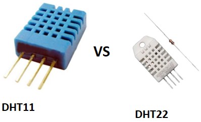 DHT11 vs DHT22: Datasheet, Pinout, and Features
12 January 20225427
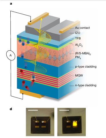 Enhancing the Efficiency of Semiconductors by Using the Spin of Electrons
11 February 20251491
 All About Video Connectors and Their Uses in Today’s Technology
02 July 20253021
 Unveiling the Magic Behind TWS Earbuds: An Analysis of Their Market, Working, and Core Components
24 July 20235795
 What is Keyboard and How to Choose It?
17 February 20226850
 Introduction to Sensors in the Internet of Things
24 September 20212387
 What is First In First Out (FIFO)?
30 November 20213393
 Introduction to Pi Filter
19 February 202115655
 Lattice FPGA: The Ultimate Guide to Low-Power, Small Form Factor Solutions
19 September 20255611
STMicroelectronics
In Stock: 2445
Minimum: 1 Multiples: 1
Qty
Unit Price
Ext Price
1
$0.242290
$0.24
10
$0.228575
$2.29
100
$0.215637
$21.56
500
$0.203431
$101.72
1000
$0.191916
$191.92
Not the price you want? Send RFQ Now and we'll contact you ASAP.
Inquire for More Quantity
![TS2431AILT]() TS2431AILT
TS2431AILTSTMicroelectronics
![TL431AIL3T]() TL431AIL3T
TL431AIL3TSTMicroelectronics
![TL431CDT]() TL431CDT
TL431CDTSTMicroelectronics
![TS3431BILT]() TS3431BILT
TS3431BILTSTMicroelectronics
![TL431ACDT]() TL431ACDT
TL431ACDTSTMicroelectronics
![TL431AIDT]() TL431AIDT
TL431AIDTSTMicroelectronics
![TS3431ILT]() TS3431ILT
TS3431ILTSTMicroelectronics
![TS4041DILT-1.2]() TS4041DILT-1.2
TS4041DILT-1.2STMicroelectronics
![TS2431BILT]() TS2431BILT
TS2431BILTSTMicroelectronics
![TS4061AILT-1.25]() TS4061AILT-1.25
TS4061AILT-1.25STMicroelectronics


