
 Product
 Brand
Brand Articles
 Tools
Tools
UC3843 PWM Controller: Pinout, Datasheet and Uses

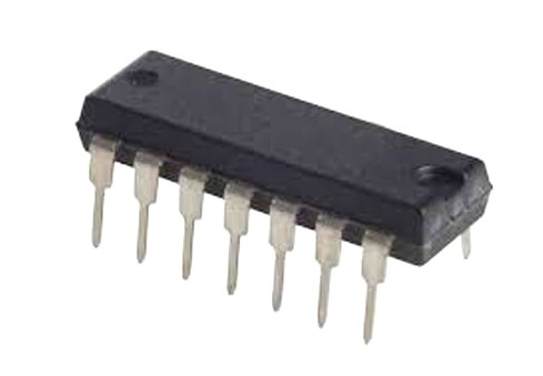
7.6V~30V 14-Pin UC3843 DC to DC converter IC 1 Outputs Up to 500kHz Transistor Driver


7.6V~30V 14-Pin UC3843 DC to DC converter IC 1 Outputs Up to 500kHz Transistor Driver
Hello everyone! I hope you all are fine today. Today, we will have a discussion about UC3843. UC3843 is a current mode PWM controller. This article mainly introduce pinout, datasheet, uses and other detailed information about On Semiconductor UC3843.

UC3843 Switching Power Supply 12V, 10A
UC3843 Description
UC3843 is basically a current mode Pulse Width Modulation (PWM) controller having fixed frequency. It is basically designed for DC to DC converter purposes as well as off line applications with minimum external components. UC3843 has three different packages.
UC3843 has several different features which make it ideal and useful for a lot of real life applications. These features may include trimmed oscillator for the control of accurate duty cycle, high gain amplifier, a temperature compensated reference, current sensing comparator and to control power MOSFET, there is a high current totem-pole output.
Moreover, some other features include temperature compensated reference and current sensing. UC 3843 can be used at several different places e.g.in switching regulators having any of the polarities as well as in transformer coupled DC to DC converters. The UC3843 have UVLO thresholds of 8.5V(on) The UC3843 can operate within 100% duty cycle.
UC3843 Pinout

UC3843 CAD Model
Symbol

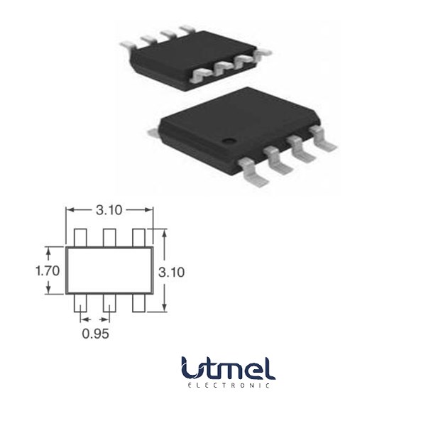
Footprint

3D Model

UC3843 Features
●Current-Mode PWM controller
●Operating Voltage: 7.0V to 8.2V
●Output pin current: 1A
●Analog input range: -0.3 to 6.3V
●Oscillation Frequency: 52 Typically Gain: 3V
●Maximum source current: 22mA
●Low Output Voltage: 0.08V
●High Output Voltage: 13.5V
●Low startup current(<1 mA)
●Pulse by pulse current limiting
●Low output resistance
●Double pulse surpression
●High current totem pole outputs
●Maximum Duty Clamp
●UVLO With Hysteresis
●Operating Frequency up to 500KHz
●Optimized For Off-line and DC-to-DC Converters
●Automatic Feed Forward Compensation Internally implemented circuits include under-voltage
●Internally Trimmed Bandgap Reference
●Low RO Error Amp
Specifications
- TypeParameter
- Mount
In electronic components, the term "Mount" typically refers to the method or process of physically attaching or fixing a component onto a circuit board or other electronic device. This can involve soldering, adhesive bonding, or other techniques to secure the component in place. The mounting process is crucial for ensuring proper electrical connections and mechanical stability within the electronic system. Different components may have specific mounting requirements based on their size, shape, and function, and manufacturers provide guidelines for proper mounting procedures to ensure optimal performance and reliability of the electronic device.
Surface Mount - Mounting Type
The "Mounting Type" in electronic components refers to the method used to attach or connect a component to a circuit board or other substrate, such as through-hole, surface-mount, or panel mount.
Surface Mount - Package / Case
refers to the protective housing that encases an electronic component, providing mechanical support, electrical connections, and thermal management.
14-SOIC (0.209, 5.30mm Width) - Number of Pins14
- Operating Temperature
The operating temperature is the range of ambient temperature within which a power supply, or any other electrical equipment, operate in. This ranges from a minimum operating temperature, to a peak or maximum operating temperature, outside which, the power supply may fail.
0°C~70°C TA - Packaging
Semiconductor package is a carrier / shell used to contain and cover one or more semiconductor components or integrated circuits. The material of the shell can be metal, plastic, glass or ceramic.
Tube - Published2002
- Part Status
Parts can have many statuses as they progress through the configuration, analysis, review, and approval stages.
Obsolete - Moisture Sensitivity Level (MSL)
Moisture Sensitivity Level (MSL) is a standardized rating that indicates the susceptibility of electronic components, particularly semiconductors, to moisture-induced damage during storage and the soldering process, defining the allowable exposure time to ambient conditions before they require special handling or baking to prevent failures
1 (Unlimited) - Frequency
In electronic components, the parameter "Frequency" refers to the rate at which a signal oscillates or cycles within a given period of time. It is typically measured in Hertz (Hz) and represents how many times a signal completes a full cycle in one second. Frequency is a crucial aspect in electronic components as it determines the behavior and performance of various devices such as oscillators, filters, and communication systems. Understanding the frequency characteristics of components is essential for designing and analyzing electronic circuits to ensure proper functionality and compatibility with other components in a system.
500kHz - Base Part Number
The "Base Part Number" (BPN) in electronic components serves a similar purpose to the "Base Product Number." It refers to the primary identifier for a component that captures the essential characteristics shared by a group of similar components. The BPN provides a fundamental way to reference a family or series of components without specifying all the variations and specific details.
UC3843 - Function
The parameter "Function" in electronic components refers to the specific role or purpose that the component serves within an electronic circuit. It defines how the component interacts with other elements, influences the flow of electrical signals, and contributes to the overall behavior of the system. Functions can include amplification, signal processing, switching, filtering, and energy storage, among others. Understanding the function of each component is essential for designing effective and efficient electronic systems.
Step-Up, Step-Up/Step-Down - Number of Outputs1
- Output Voltage
Output voltage is a crucial parameter in electronic components that refers to the voltage level produced by the component as a result of its operation. It represents the electrical potential difference between the output terminal of the component and a reference point, typically ground. The output voltage is a key factor in determining the performance and functionality of the component, as it dictates the level of voltage that will be delivered to the connected circuit or load. It is often specified in datasheets and technical specifications to ensure compatibility and proper functioning within a given system.
13.5V - Output Type
The "Output Type" parameter in electronic components refers to the type of signal or data that is produced by the component as an output. This parameter specifies the nature of the output signal, such as analog or digital, and can also include details about the voltage levels, current levels, frequency, and other characteristics of the output signal. Understanding the output type of a component is crucial for ensuring compatibility with other components in a circuit or system, as well as for determining how the output signal can be utilized or processed further. In summary, the output type parameter provides essential information about the nature of the signal that is generated by the electronic component as its output.
Transistor Driver - Voltage
Voltage is a measure of the electric potential difference between two points in an electrical circuit. It is typically represented by the symbol "V" and is measured in volts. Voltage is a crucial parameter in electronic components as it determines the flow of electric current through a circuit. It is responsible for driving the movement of electrons from one point to another, providing the energy needed for electronic devices to function properly. In summary, voltage is a fundamental concept in electronics that plays a key role in the operation and performance of electronic components.
30V - Operating Supply Current
Operating Supply Current, also known as supply current or quiescent current, is a crucial parameter in electronic components that indicates the amount of current required for the device to operate under normal conditions. It represents the current drawn by the component from the power supply while it is functioning. This parameter is important for determining the power consumption of the component and is typically specified in datasheets to help designers calculate the overall power requirements of their circuits. Understanding the operating supply current is essential for ensuring proper functionality and efficiency of electronic systems.
17mA - Nominal Supply Current
Nominal current is the same as the rated current. It is the current drawn by the motor while delivering rated mechanical output at its shaft.
17mA - Output Configuration
Output Configuration in electronic components refers to the arrangement or setup of the output pins or terminals of a device. It defines how the output signals are structured and how they interact with external circuits or devices. The output configuration can determine the functionality and compatibility of the component in a circuit design. Common types of output configurations include single-ended, differential, open-drain, and push-pull configurations, each serving different purposes and applications in electronic systems. Understanding the output configuration of a component is crucial for proper integration and operation within a circuit.
Positive - Output Current
The rated output current is the maximum load current that a power supply can provide at a specified ambient temperature. A power supply can never provide more current that it's rated output current unless there is a fault, such as short circuit at the load.
1A - Voltage - Supply (Vcc/Vdd)
Voltage - Supply (Vcc/Vdd) is a key parameter in electronic components that specifies the voltage level required for the proper operation of the device. It represents the power supply voltage that needs to be provided to the component for it to function correctly. This parameter is crucial as supplying the component with the correct voltage ensures that it operates within its specified limits and performance characteristics. It is typically expressed in volts (V) and is an essential consideration when designing and using electronic circuits to prevent damage and ensure reliable operation.
7.6V~30V - Control Features
Control features in electronic components refer to specific functionalities or characteristics that allow users to manage and regulate the operation of the component. These features are designed to provide users with control over various aspects of the component's performance, such as adjusting settings, monitoring parameters, or enabling specific modes of operation. Control features can include options for input/output configurations, power management, communication protocols, and other settings that help users customize and optimize the component's behavior according to their requirements. Overall, control features play a crucial role in enhancing the flexibility, usability, and performance of electronic components in various applications.
Frequency Control - Topology
In the context of electronic components, "topology" refers to the arrangement or configuration of the components within a circuit or system. It defines how the components are connected to each other and how signals flow between them. The choice of topology can significantly impact the performance, efficiency, and functionality of the electronic system. Common topologies include series, parallel, star, mesh, and hybrid configurations, each with its own advantages and limitations. Designers carefully select the appropriate topology based on the specific requirements of the circuit to achieve the desired performance and functionality.
Boost, Flyback - Frequency - Switching
"Frequency - Switching" in electronic components refers to the rate at which a device, such as a transistor or switching regulator, turns on and off during operation. This parameter is crucial in determining the efficiency and performance of power converters, oscillators, and other circuits that rely on rapid switching. Higher switching frequencies typically allow for smaller component sizes but may require more advanced design considerations to manage heat and electromagnetic interference.
Up to 500kHz - Rise Time
In electronics, when describing a voltage or current step function, rise time is the time taken by a signal to change from a specified low value to a specified high value.
45ns - Synchronous Rectifier
Synchronous rectification is a technique for improving the efficiency of rectification by replacing diodes with actively controlled switches, usually power MOSFETs or power bipolar junction transistors (BJT).
No - Fall Time (Typ)
Fall Time (Typ) is a parameter used to describe the time it takes for a signal to transition from a high level to a low level in an electronic component, such as a transistor or an integrated circuit. It is typically measured in nanoseconds or microseconds and is an important characteristic that affects the performance of the component in digital circuits. A shorter fall time indicates faster switching speeds and can result in improved overall circuit performance, such as reduced power consumption and increased data transmission rates. Designers often consider the fall time specification when selecting components for their circuits to ensure proper functionality and efficiency.
35 ns - Nominal Input Voltage
The actual voltage at which a circuit operates can vary from the nominal voltage within a range that permits satisfactory operation of equipment. The word “nominal” means “named”.
25V - Max Duty Cycle
Max Duty Cycle refers to the maximum percentage of time that an electronic component, such as a switch or a power supply, can be in an "on" state during a defined time period. It is an important parameter in pulse-width modulated (PWM) systems and helps determine how often a device can operate without overheating or sustaining damage. By specifying the maximum duty cycle, manufacturers provide guidance on the safe operational limits of the component, ensuring reliability and efficiency in various applications.
100 % - Duty Cycle (Max)
The "Duty Cycle (Max)" parameter in electronic components refers to the maximum percentage of time that a signal is active or on within a specific period. It is commonly used in components such as pulse-width modulation (PWM) controllers, oscillators, and timers. A duty cycle of 100% means the signal is always on, while a duty cycle of 0% means the signal is always off. Understanding the maximum duty cycle is important for ensuring proper operation and performance of the electronic component within its specified limits. It is typically expressed as a percentage and helps determine the amount of power or energy being delivered by the signal.
97% - REACH SVHC
The parameter "REACH SVHC" in electronic components refers to the compliance with the Registration, Evaluation, Authorization, and Restriction of Chemicals (REACH) regulation regarding Substances of Very High Concern (SVHC). SVHCs are substances that may have serious effects on human health or the environment, and their use is regulated under REACH to ensure their safe handling and minimize their impact.Manufacturers of electronic components need to declare if their products contain any SVHCs above a certain threshold concentration and provide information on the safe use of these substances. This information allows customers to make informed decisions about the potential risks associated with using the components and take appropriate measures to mitigate any hazards.Ensuring compliance with REACH SVHC requirements is essential for electronics manufacturers to meet regulatory standards, protect human health and the environment, and maintain transparency in their supply chain. It also demonstrates a commitment to sustainability and responsible manufacturing practices in the electronics industry.
No SVHC - RoHS Status
RoHS means “Restriction of Certain Hazardous Substances” in the “Hazardous Substances Directive” in electrical and electronic equipment.
RoHS Compliant - Lead Free
Lead Free is a term used to describe electronic components that do not contain lead as part of their composition. Lead is a toxic material that can have harmful effects on human health and the environment, so the electronics industry has been moving towards lead-free components to reduce these risks. Lead-free components are typically made using alternative materials such as silver, copper, and tin. Manufacturers must comply with regulations such as the Restriction of Hazardous Substances (RoHS) directive to ensure that their products are lead-free and environmentally friendly.
Lead Free
UC3843 Alternatives

UC3843 Internal Block Diagram

UC3843 Block Diagram

Where to use UC3843?
The UC3843 IC is a current Mode PWM Controller, meaning it can be used to provide a constant current by varying the output voltage to the load. While building Switch mode supplies with feedback there are two modes of control that is commonly used, one is voltage mode control where the output voltage will kept constant irrespective of the current (CV mode) and the other is current mode control where the output current will be constant (C mode) irrespective of the voltage.
The UC3843 can be used to regulate or limit current in application like SMPS, RPS, DC-DC Converters, Line voltage regulators etc.. So if you are looking for an IC to produce PWM signals for controlling a power switch based on the current flowing through the circuit then this IC might be the right choice for you.
How to use UC3843?
Although the IC performs a sophisticated job, using it in a circuit is fairly simple and can be done with minimum number if external components which make this IC to be a preferable choice among designers. A sample application circuit of this IC is shown below.

The IC has an under voltage protection, so care should be taken to make sure that it has an operating voltage between 7V to 8.2V. The output pin of the IC is connected to the gate driver circuit of the Power switch which is to be switched. The output pin can source upto 1A ad hence a current limiting resistor will be required. The VFB (Voltage feedback) pin acts as a feedback based on which the PWM signal is controlled. A shunt resistor is used to monitor the change in current in the circuit and then this difference voltage across the shunt is provided to the feedback pin.
The IC also has an internal oscillator which can be configured using by connecting the right value of capacitor and resistor to the pin Rt/Ct. The Datasheet recommends a value of between 470pf to 4.7nf and for the resistor a value between 5k to 100k. Refer the datasheet at the end of the page to know more about this IC. Also check out the Layout diagram at the bottom of the datasheet for a quick start. A more detailed application circuit is shown below.

Uc3843 Applications
■SMPS (Switch mode Power Supplies) circuits
■Transformers coupled DC-DC converter circuits
■Electronics power supply
■Battery drain circuit
■Load machines
■Switching regulators having any polarity
UC3843 Package

UC3843 Manufacturer
ON Semiconductor is a semiconductor supplier company, Products include power and signal management, logic, discrete, and custom devices for automotive, communications, computing, consumer, industrial, LED lighting, medical, military/aerospace and power applications. ON Semiconductor runs a network of manufacturing facilities, sales offices and design centers in North America, Europe, and the Asia Pacific regions. Its Headquarter is in Phoenix, Arizona.
Where to buy UC3843?
On the internet, you can purchase UC3843 from places like Amazon and eBay... Alternatively, you can purchase it on our website, where you will find a free datasheet to download as well as substitute parts to maintain regular manufacturing. The information is updated and supplemented on a regular basis.
Welcome to Utmel's RFQ page: https://www.utmel.com/rfq
Datasheet PDF
- Datasheets :
- ReachStatement :
1.What is the difference between TL2843B and UC3843?
The working temperature is different, the working temperature of TL2843 is 25-85℃, and the working temperature of UC3843 is 0-70℃. Can be interchanged.
2.What are the consequences of changing the reference voltage of UC3843?
The standard voltage is like a Zener diode in a voltage regulator circuit, the output voltage will rise.
3.How to repair the switching power supply of UC3843?
(1). When repairing the switching power supply, first use a multimeter to check whether the power components are broken down and short-circuited, such as the power rectifier bridge stack, switching tube, high-frequency high-power rectifier tube; whether the high-power resistor that suppresses the surge current is blown. Then check whether the resistance of each output voltage port is abnormal. If the above components are damaged, they need to be replaced.
(2). After the first step is completed, it can't work normally after turning on the power. Next, check the power factor module (PFC) and pulse width modulation module (PWM), check relevant information, and be familiar with the functions and functions of each pin of the PFC and PWM modules. A prerequisite for the normal operation of its modules.
4.How big is the sampling resistance of the switching power supply of UC3843?
The sampling resistance between the S pole of the field effect tube and the ground should be determined according to the maximum peak current of the primary side of the switching power supply, and the peak voltage of 1V cannot be exceeded at both ends of the resistance, or overcurrent protection will be used. The resistance in the electric car charger is 0.33 ohms.
5.How to use the pin 1 of UC3843?
It can be used for feedback and compensation. When used as feedback, connect pin 2 to ground and use it as negative feedback to receive the feedback voltage. When used for compensation, pin 2 is used as the feedback terminal, and a capacitor resistor is added between pin 1 and pin 2 to absorb the interference of the feedback terminal and ensure the purity of the signal.
 AS3935 Lightning Sensor: AS3935 Arduino, Pinout, Datasheet
07 July 20213529
 AO6800:30V Dual N-Channel MOSFET
08 March 2022601
 OP237EJ Operational Amplifier
06 March 2024498
 BAV99 Diodes : Datasheet, Pinout and Alternatives
06 August 20215600
 PIC12F629 Microcontroller: Features, Pinout, and Datasheet
07 December 20217492
 LMG5200 Half-Bridge Power Stage: Feature, Application, and Datasheet
16 June 20214598
 MPX2010DP Pressure Sensor: MPX2010DP Datasheet and Block Diagram
28 March 20224496
 CD4066B Bilateral Switch: Features, Speicifications and Applications
20 May 20211877
 A $39 Billion Investment Wave Expected to Boost AI and Semiconductor Stocks
26 September 20232651
 A Practical Methodology to Simulate 4H-SiC and GaN p-n Diodes with Model Parameter Adjustment in Medici
07 February 20234236
 Introduction to Potential Transformers
21 September 202011364
 The Development Trends in the Field of Electronic Component Applications
28 July 20235092
 Structure and Working Principle of Field Effect Transistors
07 April 202540504
 Opportunities and Challenges for 2D Materials
22 March 20225814
 Introduction to FinFET
18 March 202130457
 Introduction to TFT Displays
29 August 20209671
ON Semiconductor
In Stock
United States
China
Canada
Japan
Russia
Germany
United Kingdom
Singapore
Italy
Hong Kong(China)
Taiwan(China)
France
Korea
Mexico
Netherlands
Malaysia
Austria
Spain
Switzerland
Poland
Thailand
Vietnam
India
United Arab Emirates
Afghanistan
Åland Islands
Albania
Algeria
American Samoa
Andorra
Angola
Anguilla
Antigua & Barbuda
Argentina
Armenia
Aruba
Australia
Azerbaijan
Bahamas
Bahrain
Bangladesh
Barbados
Belarus
Belgium
Belize
Benin
Bermuda
Bhutan
Bolivia
Bonaire, Sint Eustatius and Saba
Bosnia & Herzegovina
Botswana
Brazil
British Indian Ocean Territory
British Virgin Islands
Brunei
Bulgaria
Burkina Faso
Burundi
Cabo Verde
Cambodia
Cameroon
Cayman Islands
Central African Republic
Chad
Chile
Christmas Island
Cocos (Keeling) Islands
Colombia
Comoros
Congo
Congo (DRC)
Cook Islands
Costa Rica
Côte d’Ivoire
Croatia
Cuba
Curaçao
Cyprus
Czechia
Denmark
Djibouti
Dominica
Dominican Republic
Ecuador
Egypt
El Salvador
Equatorial Guinea
Eritrea
Estonia
Eswatini
Ethiopia
Falkland Islands
Faroe Islands
Fiji
Finland
French Guiana
French Polynesia
Gabon
Gambia
Georgia
Ghana
Gibraltar
Greece
Greenland
Grenada
Guadeloupe
Guam
Guatemala
Guernsey
Guinea
Guinea-Bissau
Guyana
Haiti
Honduras
Hungary
Iceland
Indonesia
Iran
Iraq
Ireland
Isle of Man
Israel
Jamaica
Jersey
Jordan
Kazakhstan
Kenya
Kiribati
Kosovo
Kuwait
Kyrgyzstan
Laos
Latvia
Lebanon
Lesotho
Liberia
Libya
Liechtenstein
Lithuania
Luxembourg
Macao(China)
Madagascar
Malawi
Maldives
Mali
Malta
Marshall Islands
Martinique
Mauritania
Mauritius
Mayotte
Micronesia
Moldova
Monaco
Mongolia
Montenegro
Montserrat
Morocco
Mozambique
Myanmar
Namibia
Nauru
Nepal
New Caledonia
New Zealand
Nicaragua
Niger
Nigeria
Niue
Norfolk Island
North Korea
North Macedonia
Northern Mariana Islands
Norway
Oman
Pakistan
Palau
Palestinian Authority
Panama
Papua New Guinea
Paraguay
Peru
Philippines
Pitcairn Islands
Portugal
Puerto Rico
Qatar
Réunion
Romania
Rwanda
Samoa
San Marino
São Tomé & Príncipe
Saudi Arabia
Senegal
Serbia
Seychelles
Sierra Leone
Sint Maarten
Slovakia
Slovenia
Solomon Islands
Somalia
South Africa
South Sudan
Sri Lanka
St Helena, Ascension, Tristan da Cunha
St. Barthélemy
St. Kitts & Nevis
St. Lucia
St. Martin
St. Pierre & Miquelon
St. Vincent & Grenadines
Sudan
Suriname
Svalbard & Jan Mayen
Sweden
Syria
Tajikistan
Tanzania
Timor-Leste
Togo
Tokelau
Tonga
Trinidad & Tobago
Tunisia
Turkey
Turkmenistan
Turks & Caicos Islands
Tuvalu
U.S. Outlying Islands
U.S. Virgin Islands
Uganda
Ukraine
Uruguay
Uzbekistan
Vanuatu
Vatican City
Venezuela
Wallis & Futuna
Yemen
Zambia
Zimbabwe
![KA3525A]() KA3525A
KA3525AON Semiconductor
![UC2844BD1R2G]() UC2844BD1R2G
UC2844BD1R2GON Semiconductor
![UC3843BD1R2G]() UC3843BD1R2G
UC3843BD1R2GON Semiconductor
![UC2843BD1R2G]() UC2843BD1R2G
UC2843BD1R2GON Semiconductor
![UC3845BD1R2G]() UC3845BD1R2G
UC3845BD1R2GON Semiconductor
![UC3845BVD1R2G]() UC3845BVD1R2G
UC3845BVD1R2GON Semiconductor
![UC2845BD1R2G]() UC2845BD1R2G
UC2845BD1R2GON Semiconductor
![SG3525ADWR2G]() SG3525ADWR2G
SG3525ADWR2GON Semiconductor
![SG3525ANG]() SG3525ANG
SG3525ANGON Semiconductor
![UC3843BVD1R2G]() UC3843BVD1R2G
UC3843BVD1R2GON Semiconductor


