
 Product
 Brand
Brand Articles
 Tools
Tools
74HC75 Transparant Latch: Pinout, Equivalent and Datasheet

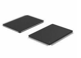
2V~6V 2 Bits Differential Latches 74HC Series 74HC75 16 Pins DUAL 16-SOIC (0.154, 3.90mm Width)
Unit Price: $0.677014
Ext Price: $0.68


2V~6V 2 Bits Differential Latches 74HC Series 74HC75 16 Pins DUAL 16-SOIC (0.154, 3.90mm Width)
The 74HC75 is a quad bistable transparent latch with complementary outputs. Two latches are simultaneously controlled by one of two active HIGH enable inputs (LE12 and LE34). Furthermore, Huge range of Semiconductors, Capacitors, Resistors and IcS in stock. Welcome RFQ.
74HC75 Pinout

Pinout
74HC75 CAD Model

PCB Symbol

PCB Footprint

3D Model
74HC75 Overview
The 74HC75 is a quad bistable transparent latch with complementary outputs. Two latches are simultaneously controlled by one of two active HIGH enable inputs (LE12 and LE34). When LEnn is HIGH, the data enters the latches and appears at the nQ outputs. The nQ outputs follow the data inputs (nD) as long as LEnn is HIGH (transparent). The data on the nD inputs one set-up time prior to the HIGH-to-LOW transition of the LEnn will be stored in the latches. The latched outputs remain stable as long as the LEnn is LOW. Inputs include clamp diodes. This enables the use of current limiting resistors to interface inputs to voltages in excess of VCC.
This article provides you with a basic overview of the 74HC75, including its pin descriptions, features and specifications, etc., to help you quickly understand what 74HC75 is.
74HC75 Features
● Complementary Q outputs
● VCC and GND on the center pins
● Low-power dissipation
● Complies with JEDEC standard no. 7A
● Input levels: CMOS level
● ESD protection:
◆ HBM EIA/JESD22-A114F exceeds 2000 V
◆ MM EIA/JESD22-A115-A exceeds 200 V
● Multiple package options
● Specified from﹣40 ℃ to ﹢80 ℃ and from﹣40 ℃ to ﹢125 ℃.
Specifications
- TypeParameter
- Factory Lead Time4 Weeks
- Mounting Type
The "Mounting Type" in electronic components refers to the method used to attach or connect a component to a circuit board or other substrate, such as through-hole, surface-mount, or panel mount.
Surface Mount - Package / Case
refers to the protective housing that encases an electronic component, providing mechanical support, electrical connections, and thermal management.
16-SOIC (0.154, 3.90mm Width) - Surface Mount
having leads that are designed to be soldered on the side of a circuit board that the body of the component is mounted on.
YES - Number of Pins16
- Operating Temperature
The operating temperature is the range of ambient temperature within which a power supply, or any other electrical equipment, operate in. This ranges from a minimum operating temperature, to a peak or maximum operating temperature, outside which, the power supply may fail.
-40°C~125°C - Packaging
Semiconductor package is a carrier / shell used to contain and cover one or more semiconductor components or integrated circuits. The material of the shell can be metal, plastic, glass or ceramic.
Tube - Series
In electronic components, the "Series" refers to a group of products that share similar characteristics, designs, or functionalities, often produced by the same manufacturer. These components within a series typically have common specifications but may vary in terms of voltage, power, or packaging to meet different application needs. The series name helps identify and differentiate between various product lines within a manufacturer's catalog.
74HC - JESD-609 Code
The "JESD-609 Code" in electronic components refers to a standardized marking code that indicates the lead-free solder composition and finish of electronic components for compliance with environmental regulations.
e4 - Part Status
Parts can have many statuses as they progress through the configuration, analysis, review, and approval stages.
Active - Moisture Sensitivity Level (MSL)
Moisture Sensitivity Level (MSL) is a standardized rating that indicates the susceptibility of electronic components, particularly semiconductors, to moisture-induced damage during storage and the soldering process, defining the allowable exposure time to ambient conditions before they require special handling or baking to prevent failures
1 (Unlimited) - Number of Terminations16
- Terminal Finish
Terminal Finish refers to the surface treatment applied to the terminals or leads of electronic components to enhance their performance and longevity. It can improve solderability, corrosion resistance, and overall reliability of the connection in electronic assemblies. Common finishes include nickel, gold, and tin, each possessing distinct properties suitable for various applications. The choice of terminal finish can significantly impact the durability and effectiveness of electronic devices.
Nickel/Palladium/Gold (Ni/Pd/Au) - Voltage - Supply
Voltage - Supply refers to the range of voltage levels that an electronic component or circuit is designed to operate with. It indicates the minimum and maximum supply voltage that can be applied for the device to function properly. Providing supply voltages outside this range can lead to malfunction, damage, or reduced performance. This parameter is critical for ensuring compatibility between different components in a circuit.
2V~6V - Terminal Position
In electronic components, the term "Terminal Position" refers to the physical location of the connection points on the component where external electrical connections can be made. These connection points, known as terminals, are typically used to attach wires, leads, or other components to the main body of the electronic component. The terminal position is important for ensuring proper connectivity and functionality of the component within a circuit. It is often specified in technical datasheets or component specifications to help designers and engineers understand how to properly integrate the component into their circuit designs.
DUAL - Terminal Form
Occurring at or forming the end of a series, succession, or the like; closing; concluding.
GULL WING - Peak Reflow Temperature (Cel)
Peak Reflow Temperature (Cel) is a parameter that specifies the maximum temperature at which an electronic component can be exposed during the reflow soldering process. Reflow soldering is a common method used to attach electronic components to a circuit board. The Peak Reflow Temperature is crucial because it ensures that the component is not damaged or degraded during the soldering process. Exceeding the specified Peak Reflow Temperature can lead to issues such as component failure, reduced performance, or even permanent damage to the component. It is important for manufacturers and assemblers to adhere to the recommended Peak Reflow Temperature to ensure the reliability and functionality of the electronic components.
NOT SPECIFIED - Number of Functions2
- Supply Voltage
Supply voltage refers to the electrical potential difference provided to an electronic component or circuit. It is crucial for the proper operation of devices, as it powers their functions and determines performance characteristics. The supply voltage must be within specified limits to ensure reliability and prevent damage to components. Different electronic devices have specific supply voltage requirements, which can vary widely depending on their design and intended application.
5V - Time@Peak Reflow Temperature-Max (s)
Time@Peak Reflow Temperature-Max (s) refers to the maximum duration that an electronic component can be exposed to the peak reflow temperature during the soldering process, which is crucial for ensuring reliable solder joint formation without damaging the component.
NOT SPECIFIED - Base Part Number
The "Base Part Number" (BPN) in electronic components serves a similar purpose to the "Base Product Number." It refers to the primary identifier for a component that captures the essential characteristics shared by a group of similar components. The BPN provides a fundamental way to reference a family or series of components without specifying all the variations and specific details.
74HC75 - Pin Count
a count of all of the component leads (or pins)
16 - Output Type
The "Output Type" parameter in electronic components refers to the type of signal or data that is produced by the component as an output. This parameter specifies the nature of the output signal, such as analog or digital, and can also include details about the voltage levels, current levels, frequency, and other characteristics of the output signal. Understanding the output type of a component is crucial for ensuring compatibility with other components in a circuit or system, as well as for determining how the output signal can be utilized or processed further. In summary, the output type parameter provides essential information about the nature of the signal that is generated by the electronic component as its output.
Differential - Circuit
The parameter "Circuit" in electronic components refers to the interconnected arrangement of various electronic elements such as resistors, capacitors, inductors, and active devices like transistors. It defines the path through which electric current flows and establishes the operational behavior of the components within that system. Circuits can be classified as analog or digital, depending on the type of signals they handle, and can vary in complexity from simple series or parallel configurations to intricate designs used in advanced applications.
2:2 - Supply Voltage-Max (Vsup)
The parameter "Supply Voltage-Max (Vsup)" in electronic components refers to the maximum voltage that can be safely applied to the component without causing damage. It is an important specification to consider when designing or using electronic circuits to ensure the component operates within its safe operating limits. Exceeding the maximum supply voltage can lead to overheating, component failure, or even permanent damage. It is crucial to adhere to the specified maximum supply voltage to ensure the reliable and safe operation of the electronic component.
6V - Supply Voltage-Min (Vsup)
The parameter "Supply Voltage-Min (Vsup)" in electronic components refers to the minimum voltage level required for the component to operate within its specified performance range. This parameter indicates the lowest voltage that can be safely applied to the component without risking damage or malfunction. It is crucial to ensure that the supply voltage provided to the component meets or exceeds this minimum value to ensure proper functionality and reliability. Failure to adhere to the specified minimum supply voltage may result in erratic behavior, reduced performance, or even permanent damage to the component.
2V - Output Current
The rated output current is the maximum load current that a power supply can provide at a specified ambient temperature. A power supply can never provide more current that it's rated output current unless there is a fault, such as short circuit at the load.
5.2mA - Number of Bits2
- Family
In electronic components, the parameter "Family" typically refers to a categorization or classification system used to group similar components together based on their characteristics, functions, or applications. This classification helps users easily identify and select components that meet their specific requirements. The "Family" parameter can include various subcategories such as resistors, capacitors, diodes, transistors, integrated circuits, and more. Understanding the "Family" of an electronic component can provide valuable information about its compatibility, performance specifications, and potential uses within a circuit or system. It is important to consider the "Family" parameter when designing or troubleshooting electronic circuits to ensure proper functionality and compatibility with other components.
HC/UH - Logic Type
Logic Type in electronic components refers to the classification of circuits based on the logical operations they perform. It includes types such as AND, OR, NOT, NAND, NOR, XOR, and XNOR, each defining the relationship between binary inputs and outputs. The logic type determines how the inputs affect the output state based on specific rules of Boolean algebra. This classification is crucial for designing digital circuits and systems, enabling engineers to select appropriate components for desired functionalities.
D-Type Transparent Latch - Output Polarity
Output polarity in electronic components refers to the orientation of the output signal in relation to the ground or reference voltage. It indicates whether the output voltage is positive or negative with respect to the ground. Positive output polarity means the signal is higher than the ground potential, while negative output polarity signifies that the signal is lower than the ground. This characteristic is crucial for determining compatibility with other components in a circuit and ensuring proper signal processing.
COMPLEMENTARY - Trigger Type
Trigger Type in electronic components refers to the mechanism or method by which a device, such as a flip-flop or timer, responds to an input signal. It defines how the device transitions between states based on specific conditions, such as rising or falling edges of a signal, levels, or pulses. Different trigger types such as edge-triggered, level-triggered, or pulse-triggered influence the timing and behavior of the circuit, thereby determining how input signals affect the output in various applications.
HIGH LEVEL - Independent Circuits
The term "Independent Circuits" in electronic components refers to the ability of a device to function as a separate and self-contained circuit within a larger system. In the context of electronic components, having independent circuits means that each circuit can operate autonomously without being directly affected by other circuits in the system. This feature allows for better isolation, control, and troubleshooting of individual circuits within a complex electronic system. Independent circuits are commonly found in devices such as integrated circuits, where multiple functional blocks are designed to operate independently to perform specific tasks efficiently. Overall, the presence of independent circuits in electronic components enhances the reliability, flexibility, and performance of the system as a whole.
2 - Delay Time - Propagation
Delay Time - Propagation is a parameter in electronic components that refers to the time it takes for a signal to travel from the input of a component to its output. It is a crucial characteristic in digital circuits as it determines the speed at which signals can propagate through the component. A shorter delay time means faster signal propagation, which is important for ensuring proper timing and performance in electronic systems. Engineers often analyze and optimize delay time propagation to improve the overall speed and efficiency of electronic devices.
11ns - Length9.9mm
- Height Seated (Max)
Height Seated (Max) is a parameter in electronic components that refers to the maximum allowable height of the component when it is properly seated or installed on a circuit board or within an enclosure. This specification is crucial for ensuring proper fit and alignment within the overall system design. Exceeding the maximum seated height can lead to mechanical interference, electrical shorts, or other issues that may impact the performance and reliability of the electronic device. Manufacturers provide this information to help designers and engineers select components that will fit within the designated space and function correctly in the intended application.
1.75mm - Width3.9mm
- RoHS Status
RoHS means “Restriction of Certain Hazardous Substances” in the “Hazardous Substances Directive” in electrical and electronic equipment.
ROHS3 Compliant
74HC75 Functional Block Diagram

Functional diagram

Logic diagram

Logic symbol

IEC logic symbol
74HC75 Equivalent
| Model number | Manufacturer | Description |
| HD74HC259RP | Renesas Electronics Corporation | D LATCH, PDSO16, FP-16DN |
| M38510/31604BXA | Defense Supply Center Columbus | IC LS SERIES, POSITIVE EDGE TRIGGERED D LATCH, COMPLEMENTARY OUTPUT, CQCC20, CERAMIC, LCC-20, FF/Latch |
| SN74ALS174DE4 | Texas Instruments | ALS SERIES, POSITIVE EDGE TRIGGERED D FLIP-FLOP, TRUE OUTPUT, PDSO16, GREEN, PLASTIC, MS-012AC, SOIC-16 |
| M38510/30106BEB | NXP Semiconductors | IC LS SERIES, HEX POSITIVE EDGE TRIGGERED D FLIP-FLOP, COMPLEMENTARY OUTPUT, CDIP16, CERAMIC, DIP-16, FF/Latch |
| HD74HC173RP | Renesas Electronics Corporation | HC/UH SERIES, POSITIVE EDGE TRIGGERED D FLIP-FLOP, TRUE OUTPUT, PDSO16, FP-16DN |
| HD74AC112P | Renesas Electronics Corporation | AC SERIES, DUAL NEGATIVE EDGE TRIGGERED J-K FLIP-FLOP, COMPLEMENTARY OUTPUT, PDIP16, DP-16 |
| MC74AC112DR2 | Motorola Mobility LLC | AC SERIES, DUAL NEGATIVE EDGE TRIGGERED J-K FLIP-FLOP, COMPLEMENTARY OUTPUT, PDSO16, PLASTIC, SOIC-16 |
| 74HC174D,652 | NXP Semiconductors | 74HC(T)174 - Hex D-type flip-flop with reset; positive-edge trigger SOP 16-Pin |
| 935174560118 | NXP Semiconductors | IC HC/UH SERIES, POSITIVE EDGE TRIGGERED D FLIP-FLOP, COMPLEMENTARY OUTPUT, PDSO16, 4.40 MM, PLASTIC, MO-153, SOT-403-1, TSSOP-16, FF/Latch |
| 74HC109DB | Nexperia | J-Kbar Flip-Flop |
Parts with Similar Specs
- ImagePart NumberManufacturerPackage / CaseNumber of PinsSupply VoltageRoHS StatusOutput TypeMoisture Sensitivity Level (MSL)Part StatusMounting TypeView Compare
![74HC75D,652]()
74HC75D,652
16-SOIC (0.154, 3.90mm Width)
16
5 V
ROHS3 Compliant
Differential
1 (Unlimited)
Active
Surface Mount
![74AHC74D,118]()
14-SOIC (0.154, 3.90mm Width)
14
5 V
ROHS3 Compliant
Differential
1 (Unlimited)
Active
Surface Mount
![74HC74D,653]()
14-SOIC (0.154, 3.90mm Width)
14
5 V
ROHS3 Compliant
Differential
1 (Unlimited)
Active
Surface Mount
![74HC74D,652]()
14-SOIC (0.154, 3.90mm Width)
14
-
ROHS3 Compliant
Differential
1 (Unlimited)
Active
Surface Mount


74HC75 Package

Package outline
74HC75 Manufacturer
Nexperia is dedicated to Discretes, Logic and MOSFETs devices. This new company became independent at the beginning of 2017. Nexperia is a leading expert in the high-volume production of essential semiconductors, components that are required by every electronic design in the world. The company’s extensive portfolio includes diodes, bipolar transistors, ESD protection devices, MOSFETs, GaN FETs and analog & logic ICs. With decades of experience in supplying to the world’s leading companies, Nexperia has over 12,000 employees across Asia, Europe and the US. Nexperia creates efficient devices with best-in-class Quality. It has an extensive portfolio, produced to meet the stringent standards set by the Automotive industry. Its belief that efficiency wins is backed by flawless execution that meets the stringent requirements of the market and customers. Every Nexperia employee is tasked with the responsibility of maintaining Quality. Nexperia is a worldwide network built on passion and commitment to our work, belief in our goals and a drive to succeed.
Datasheet PDF
- PCN Packaging :
- PCN Design/Specification :
- Datasheets :
- PCN Assembly/Origin :
- RohsStatement :
Trend Analysis
What is the essential property of the 74HC75?
The 74HC75 is a quad bistable transparent latch with complementary outputs. Two latches are simultaneously controlled by one of two active HIGH enable inputs (LE12 and LE34).
Which integrated blocks have similar functions to 74HC75 and can replace 74HC75?
7475, 74LS75.
 KSZ8895MQXI Ethernet Switch SPI Interface 128-PQFP: Datasheet, Pinout, and equivalent
11 February 20222147
 TPS1H200AQDGNRQ1 High-Side Switch: Diagram, Pinout, and Datasheet
30 March 20222770
 LM336 2.5V Regulator Diodes: Datasheet, Reference and Circuit
22 September 20217927
 LT1085 Low Dropout Positive Regulators: Datasheet, Circuit and Replacement
24 November 20214108
![How to Use AP7366-W5-7 Linear Regulator?[Datasheet&Pinout]](https://res.utmel.com/Images/Article/0d92e404-f6b3-4194-8608-519674dc1ace.png) How to Use AP7366-W5-7 Linear Regulator?[Datasheet&Pinout]
How to Use AP7366-W5-7 Linear Regulator?[Datasheet&Pinout]20 February 20231032
 TCRT5000 IR Sensor: Datasheet, Pinout and Circuit
19 October 202138743
 PCA9685 LED Controller: Datasheet, PCA9685 Arduino, Schematic
10 December 202115339
 ABLIC U.S.A. Inc. S-7760A4115-HCT1 I/O Expander: Product Overview and Applications
07 March 2024427
 Electronic Components in the Smart Home System
24 April 20252885
 An Overview of Fiber Optic Cable
10 August 20216914
 How to treat 5G?
23 October 20212383
 How much do you know about Button Battery?
15 March 20245235
 What is Safety Relay?
12 April 202525635
 Semiconductor Materials:Types, Properties and Production Process
21 October 202526301
 What is an ASIC Chip?
07 January 202615093
 7 Promising Semiconductor Stocks Amid U.S.-China Chip War
18 September 20234254
Nexperia USA Inc.
In Stock: 21
Minimum: 1 Multiples: 1
Qty
Unit Price
Ext Price
1
$0.677014
$0.68
10
$0.638692
$6.39
100
$0.602540
$60.25
500
$0.568434
$284.22
1000
$0.536258
$536.26
Not the price you want? Send RFQ Now and we'll contact you ASAP.
Inquire for More Quantity
![74HC573PW,118]() 74HC573PW,118
74HC573PW,118Nexperia USA Inc.
![74HC573D,653]() 74HC573D,653
74HC573D,653Nexperia USA Inc.
![74HC259D,653]() 74HC259D,653
74HC259D,653Nexperia USA Inc.
![74HC373PW,118]() 74HC373PW,118
74HC373PW,118Nexperia USA Inc.
![74HCT573DB,118]() 74HCT573DB,118
74HCT573DB,118Nexperia USA Inc.
![74HCT259D,653]() 74HCT259D,653
74HCT259D,653Nexperia USA Inc.
![74LVT573PW,118]() 74LVT573PW,118
74LVT573PW,118Nexperia USA Inc.
![HEF40373BT,653]() HEF40373BT,653
HEF40373BT,653Nexperia USA Inc.
![74HCT373D,653]() 74HCT373D,653
74HCT373D,653Nexperia USA Inc.
![74LVC573ABQ,115]() 74LVC573ABQ,115
74LVC573ABQ,115Nexperia USA Inc.


