DB107 Rectifiers: Features, Pinout, and Datasheet [Video&FAQ]
Single Phase Bridge Rectifier Through Hole -55°C~150°C TJ 10μA @ 1000V 1.1V @ 1A 4-Termination 1-Phase 4-EDIP (0.321, 8.15mm) Bulk
Unit Price: $0.756847
Ext Price: $0.76


Single Phase Bridge Rectifier Through Hole -55°C~150°C TJ 10μA @ 1000V 1.1V @ 1A 4-Termination 1-Phase 4-EDIP (0.321, 8.15mm) Bulk
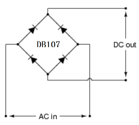
DB107 are 1.0A Single-Phase Glass Passivated Bridge Rectifiers. As a power component. This article mainly introduces features, pinout, datasheet and other detailed information about Comchip Technology DB107.

what is DB107 in tamil
DB107 Description
DB107 Pinout
DB107 CAD Model
The followings are the Symbol, Footprint, 3D Model of DB107.
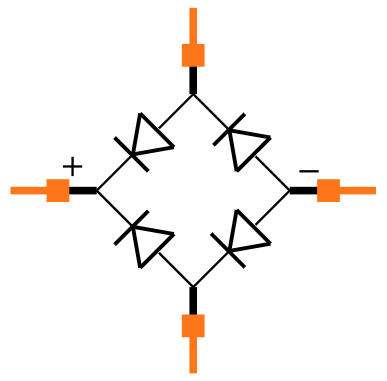
Symbol
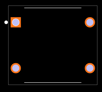
Footprint
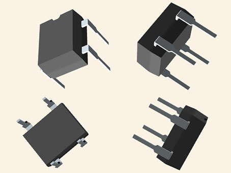
3D Model
DB107 Features
● Rating To 1000V PRV
● Ideal For Printed Circuit Board
● Low Forward Voltage Drop
● High Current Capability
● The Plastic Material Has UL Flammability Classification 94V-0
● Lead-Free Finish/Rohs Compliant
● 4-PIN DIP Package
● Glass Passivated Diode Construction
● UL Recognized File # E349301
● Moisture Sensitivity Level 1
● Halogen Free Available Upon Request By Adding Suffix "-HF"
Specifications
- TypeParameter
- Factory Lead Time10 Weeks
- Mount
In electronic components, the term "Mount" typically refers to the method or process of physically attaching or fixing a component onto a circuit board or other electronic device. This can involve soldering, adhesive bonding, or other techniques to secure the component in place. The mounting process is crucial for ensuring proper electrical connections and mechanical stability within the electronic system. Different components may have specific mounting requirements based on their size, shape, and function, and manufacturers provide guidelines for proper mounting procedures to ensure optimal performance and reliability of the electronic device.
Through Hole - Mounting Type
The "Mounting Type" in electronic components refers to the method used to attach or connect a component to a circuit board or other substrate, such as through-hole, surface-mount, or panel mount.
Through Hole - Package / Case
refers to the protective housing that encases an electronic component, providing mechanical support, electrical connections, and thermal management.
4-EDIP (0.321, 8.15mm) - Number of Pins4
- Diode Element Material
The parameter "Diode Element Material" refers to the specific semiconductor material used in the construction of a diode. This material determines the electrical characteristics and performance of the diode, including its forward voltage drop, reverse breakdown voltage, and switching speed. Common diode element materials include silicon, germanium, and gallium arsenide, each offering different advantages for various applications. The choice of material impacts the diode's efficiency, thermal stability, and overall suitability for specific electronic circuits.
SILICON - Number of Elements4
- Operating Temperature
The operating temperature is the range of ambient temperature within which a power supply, or any other electrical equipment, operate in. This ranges from a minimum operating temperature, to a peak or maximum operating temperature, outside which, the power supply may fail.
-55°C~150°C TJ - Packaging
Semiconductor package is a carrier / shell used to contain and cover one or more semiconductor components or integrated circuits. The material of the shell can be metal, plastic, glass or ceramic.
Bulk - Published2000
- Part Status
Parts can have many statuses as they progress through the configuration, analysis, review, and approval stages.
Active - Moisture Sensitivity Level (MSL)
Moisture Sensitivity Level (MSL) is a standardized rating that indicates the susceptibility of electronic components, particularly semiconductors, to moisture-induced damage during storage and the soldering process, defining the allowable exposure time to ambient conditions before they require special handling or baking to prevent failures
1 (Unlimited) - Number of Terminations4
- ECCN Code
An ECCN (Export Control Classification Number) is an alphanumeric code used by the U.S. Bureau of Industry and Security to identify and categorize electronic components and other dual-use items that may require an export license based on their technical characteristics and potential for military use.
EAR99 - Additional Feature
Any Feature, including a modified Existing Feature, that is not an Existing Feature.
UL RECOGNIZED - Terminal Position
In electronic components, the term "Terminal Position" refers to the physical location of the connection points on the component where external electrical connections can be made. These connection points, known as terminals, are typically used to attach wires, leads, or other components to the main body of the electronic component. The terminal position is important for ensuring proper connectivity and functionality of the component within a circuit. It is often specified in technical datasheets or component specifications to help designers and engineers understand how to properly integrate the component into their circuit designs.
DUAL - Peak Reflow Temperature (Cel)
Peak Reflow Temperature (Cel) is a parameter that specifies the maximum temperature at which an electronic component can be exposed during the reflow soldering process. Reflow soldering is a common method used to attach electronic components to a circuit board. The Peak Reflow Temperature is crucial because it ensures that the component is not damaged or degraded during the soldering process. Exceeding the specified Peak Reflow Temperature can lead to issues such as component failure, reduced performance, or even permanent damage to the component. It is important for manufacturers and assemblers to adhere to the recommended Peak Reflow Temperature to ensure the reliability and functionality of the electronic components.
NOT SPECIFIED - Time@Peak Reflow Temperature-Max (s)
Time@Peak Reflow Temperature-Max (s) refers to the maximum duration that an electronic component can be exposed to the peak reflow temperature during the soldering process, which is crucial for ensuring reliable solder joint formation without damaging the component.
NOT SPECIFIED - Base Part Number
The "Base Part Number" (BPN) in electronic components serves a similar purpose to the "Base Product Number." It refers to the primary identifier for a component that captures the essential characteristics shared by a group of similar components. The BPN provides a fundamental way to reference a family or series of components without specifying all the variations and specific details.
DB107 - Diode Type
In electronic components, the parameter "Diode Type" refers to the specific type or configuration of a diode, which is a semiconductor device that allows current to flow in one direction only. There are various types of diodes, each designed for specific applications and functions. Common diode types include rectifier diodes, zener diodes, light-emitting diodes (LEDs), and Schottky diodes, among others. The diode type determines the diode's characteristics, such as forward voltage drop, reverse breakdown voltage, and maximum current rating, making it crucial for selecting the right diode for a particular circuit or application. Understanding the diode type is essential for ensuring proper functionality and performance in electronic circuits.
Single Phase - Current - Reverse Leakage @ Vr
Current - Reverse Leakage @ Vr is a parameter that describes the amount of current that flows in the reverse direction through a diode or other semiconductor component when a reverse voltage (Vr) is applied across it. This leakage current is typically very small, but it is important to consider in electronic circuits as it can affect the overall performance and reliability of the component. The reverse leakage current is influenced by factors such as the material properties of the semiconductor, temperature, and the magnitude of the reverse voltage applied. Manufacturers provide this parameter in datasheets to help engineers and designers understand the behavior of the component in reverse bias conditions.
10μA @ 1000V - Voltage - Forward (Vf) (Max) @ If
The parameter "Voltage - Forward (Vf) (Max) @ If" refers to the maximum voltage drop across a diode when it is forward-biased and conducting a specified forward current (If). It indicates the maximum potential difference the diode can withstand while allowing current to flow in the forward direction without breaking down. This value is crucial for designing circuits as it helps determine how much voltage will be lost across the diode during operation. Higher Vf values can lead to reduced efficiency in power applications, making this parameter essential for optimizing circuit performance.
1.1V @ 1A - Output Current-Max
Output Current-Max is a parameter in electronic components that specifies the maximum amount of current that can be safely drawn from the output of the component without causing damage. It is an important specification to consider when designing circuits to ensure that the component can handle the required current without overheating or failing. Exceeding the maximum output current can lead to performance issues, component damage, or even complete failure of the circuit. It is crucial to adhere to the specified maximum output current to ensure the reliable operation of the electronic component and the overall circuit.
1A - Current - Average Rectified (Io)
The parameter "Current - Average Rectified (Io)" in electronic components refers to the average value of the rectified current flowing through the component. This parameter is important in determining the average power dissipation and thermal considerations of the component. It is typically specified in datasheets for diodes, rectifiers, and other components that handle alternating current (AC) and convert it to direct current (DC). Understanding the average rectified current helps in selecting the appropriate component for a given application to ensure reliable operation and prevent overheating.
1A - Number of Phases1
- Non-rep Pk Forward Current-Max
Non-rep Pk Forward Current-Max refers to the maximum forward current that a semiconductor device, such as a diode or LED, can handle in a pulsed or non-repetitive manner without being damaged. This parameter is essential for designers to ensure that the component operates reliably under specific conditions, particularly during transient events like switching or fault conditions. Exceeding this limit can lead to overheating or failure of the device.
30A - Voltage - Peak Reverse (Max)
Voltage - Peak Reverse (Max) refers to the maximum voltage that a semiconductor device, typically a diode, can withstand in the reverse-bias direction without undergoing breakdown. It is crucial for ensuring reliable operation in circuits where the direction of the voltage may change. Exceeding this parameter can result in permanent damage to the component, leading to failure in its intended function. This specification is particularly important in applications involving rectification or signal modulation.
1kV - Breakdown Voltage-Min
Breakdown Voltage-Min, also known as minimum breakdown voltage, is a crucial parameter in electronic components, especially in devices like diodes, transistors, and capacitors. It refers to the minimum voltage at which the component experiences a breakdown and allows a significant current to flow through it. This breakdown voltage is a critical threshold beyond which the component may get damaged or exhibit unexpected behavior. Manufacturers specify this parameter to ensure that the component operates within safe limits and to help designers select the appropriate components for their circuit requirements. It is essential to consider the Breakdown Voltage-Min when designing circuits to prevent overloading or damaging the components.
1000V - RoHS Status
RoHS means “Restriction of Certain Hazardous Substances” in the “Hazardous Substances Directive” in electrical and electronic equipment.
ROHS3 Compliant
DB107 Layout
DB107 Marking Code
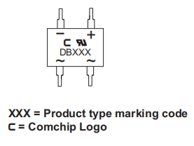
| Part Number | Marking code |
| DB101-G | DB101 |
| DB102-G | DB102 |
| DB103-G | DB103 |
| DB104-G | DB104 |
| DB105-G | DB105 |
| DB106-G | DB106 |
| DB107-G | DB107 |
Marking Code
DB107 Alternatives
| Part Number | Description | Manufacturer |
| DF10SDIODES | Bridge Rectifier Diode, 1A, 1000V V(RRM), | Shanghai Lunsure Electronic Technology Co Ltd |
| DF10MDIODES | Bridge Rectifier Diode, 1 Phase, 1A, 1000V V(RRM), Silicon, | General Instrument Corp |
DB107 Applications
● Ideal For Printed Circuit Board
● Chargers
● Power Supplies
● Lighting
● Small Household Appliances, Etc
DB107 Package
DB107 Manufacturer
Comchip Technology Corporation is in a leading position in the design and manufacture of discrete SMD semiconductor systems. Comchip provides bridge rectifiers, fast and efficient rectifiers, switching diodes, Zener diodes, Schottky diodes, TVS and ESD surge protectors with unique research and proprietary production skills. For your application, we provide the correct diode. Comchip Technology was the first company to establish a RoHS-compliant DFN/flat chip package, using gold terminations to eliminate the potential of tin whiskers. SOD-323F (1005), SOD-523F (0603), SOD-723F (0503), SOD-923F (0402) and 0201 packages can be used in DFN packages.
Comchip devices are suitable for many applications, including lighting, automotive, industrial, TFT-LCD, networking/telecommunications, mobile, consumer electronics, and high-reliability applications with zero tin whisker potential. The computer is equipped with a variety of computers. Comchip has passed TS16949, ISO9001 and ISO14001 certifications to provide better quality and reliability. Comchip bridge corrector and TVS passed the UL safety equipment application test as an additional safety layer. Many Comchip diodes meet the AEC-Q101 automotive stress-test standard and are suitable for automotive and high-reliability applications.
Trend Analysis
Datasheet PDF
- Datasheets :
- PCN Design/Specification :
- PCN Packaging :
- Environmental Information :
1.What is the difference between DB107 and DB107S?
They are all 100V/1A rectifier bridge stacks, the difference is that DB107 is a plug-in, and DB107S is a patch model.
2.What is the difference between DB207 and DB107 rectifier bridge?
The difference is that the rated operating current is different. DB107 is 1A, and DB207 is 2A. The withstand voltage is the same, both are 1000V.
3.Can DB107 and MB10F be used interchangeably?
All of them are 1A1000V, which can be a perfect substitute, but it is best to check whether the filter capacitor or other components are short-circuited, so as to avoid soldering and burning. At the same time, note that the pins should be soldered in the correct position.
4. What is DB107?
1.0A Single-Phase Glass Passivated Bridge Rectifier.
5. What is widely used in electronic equipment?
DB107 rectifier bridge.
6. How many diodes does DB107 have?
Four.
 HX711 Analog-to-Digital Converter: 24-Bit ADC, HX711 Datasheet, and Load Cell
26 January 202220265
 ULN2004A Darlington Array: Pinout, Equivalent and Datasheet
29 November 20216563
 TEA2025 Stereo Audio Amplifier: Circuit, Datasheet and Equivalent
20 October 202136263
 Technical Features and Specifications of STM32F030R8T6 Microcontroller
24 July 2025283
![UVG100 SENSOR PHOTODIODE 254NM 10MM[FAQ]: Datasheet, Features, and Parameters](https://res.utmel.com/Images/Article/e04f0428-0626-4324-9216-3255cbf8f98c.jpg) UVG100 SENSOR PHOTODIODE 254NM 10MM[FAQ]: Datasheet, Features, and Parameters
UVG100 SENSOR PHOTODIODE 254NM 10MM[FAQ]: Datasheet, Features, and Parameters29 March 2022532
 A4988 DMOS Microstepping Driver: Datasheet, Pinout, and DRV8825 vs. A4988
25 September 20217021
 ATMEGA328P Microcontroller: Pinout, Datasheet and Application
07 July 202110316
 RH850/F1L Microcontroller for Automotive Body Applications: Datasheet Overview
29 February 2024143
 How Can Memory Adapt and Influence the Smart Age of the Future?
11 October 20221163
 What is Network Topology?
23 December 20213651
 Low Temperature Drift Resistors Increase the Accuracy of Analog Circuits
11 February 20251024
 800G Optical Transceivers: The Guide for AI Data Centers
24 December 20251486
 Analysis of Magnetic and Thermal Semiconductor Power Modules
13 March 20241907
 Understanding Machine Vision and Visual Sensor
27 September 20211810
 Emerging Storage Technologies: MRAM, RRAM, and PCRAM
08 January 20269357
 What are Shunts?
07 December 20205718
Comchip Technology
In Stock: 86004
Minimum: 1 Multiples: 1
Qty
Unit Price
Ext Price
1
$0.756847
$0.76
10
$0.714007
$7.14
100
$0.673591
$67.36
500
$0.635463
$317.73
1000
$0.599494
$599.49
Not the price you want? Send RFQ Now and we'll contact you ASAP.
Inquire for More Quantity


