
L78L05ABUTR Regulator: Features, Applications and Datasheet


Fixed L78L05 PMIC 3 TO-243AA
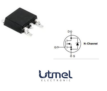
The L78L05ABUTR is a three-terminal positive voltage regulator that uses thermal shutdown and internal current limiting, which practically makes them unbreakable. This article will introduce its features, applications and datasheet.
L78L05ABUTR Description
The L78L05ABUTR is a three-terminal positive voltage regulator that uses thermal shutdown and internal current limiting, which practically makes them unbreakable. With a sufficient heat sink, they have the capacity to produce currents as high as 100mA. They are designed to be fixed voltage regulators for use in a variety of settings, such as local or on-card control to reduce noise and solve distribution issues related to single-point regulation. Additionally, they can be utilized to create high-current voltage regulators by combining with power pass components. It provides an improvement over Zener diode/resistor combinations, as well as a reduction in noise and quiescent current.
L78L05ABUTR Features
Protection Against Thermal Overload
Protection Against Short Circuits
No Need for External Components
Choose from ±4% (A) or ±8% (C) selection options.
Specifications
- TypeParameter
- Lifecycle Status
Lifecycle Status refers to the current stage of an electronic component in its product life cycle, indicating whether it is active, obsolete, or transitioning between these states. An active status means the component is in production and available for purchase. An obsolete status indicates that the component is no longer being manufactured or supported, and manufacturers typically provide a limited time frame for support. Understanding the lifecycle status is crucial for design engineers to ensure continuity and reliability in their projects.
ACTIVE (Last Updated: 7 months ago) - Factory Lead Time15 Weeks
- Mount
In electronic components, the term "Mount" typically refers to the method or process of physically attaching or fixing a component onto a circuit board or other electronic device. This can involve soldering, adhesive bonding, or other techniques to secure the component in place. The mounting process is crucial for ensuring proper electrical connections and mechanical stability within the electronic system. Different components may have specific mounting requirements based on their size, shape, and function, and manufacturers provide guidelines for proper mounting procedures to ensure optimal performance and reliability of the electronic device.
Surface Mount - Mounting Type
The "Mounting Type" in electronic components refers to the method used to attach or connect a component to a circuit board or other substrate, such as through-hole, surface-mount, or panel mount.
Surface Mount - Package / Case
refers to the protective housing that encases an electronic component, providing mechanical support, electrical connections, and thermal management.
TO-243AA - Number of Pins3
- Weight4.535924g
- Operating Temperature
The operating temperature is the range of ambient temperature within which a power supply, or any other electrical equipment, operate in. This ranges from a minimum operating temperature, to a peak or maximum operating temperature, outside which, the power supply may fail.
-40°C~125°C - Packaging
Semiconductor package is a carrier / shell used to contain and cover one or more semiconductor components or integrated circuits. The material of the shell can be metal, plastic, glass or ceramic.
Tape & Reel (TR) - JESD-609 Code
The "JESD-609 Code" in electronic components refers to a standardized marking code that indicates the lead-free solder composition and finish of electronic components for compliance with environmental regulations.
e3 - Part Status
Parts can have many statuses as they progress through the configuration, analysis, review, and approval stages.
Active - Moisture Sensitivity Level (MSL)
Moisture Sensitivity Level (MSL) is a standardized rating that indicates the susceptibility of electronic components, particularly semiconductors, to moisture-induced damage during storage and the soldering process, defining the allowable exposure time to ambient conditions before they require special handling or baking to prevent failures
1 (Unlimited) - Number of Terminations3
- ECCN Code
An ECCN (Export Control Classification Number) is an alphanumeric code used by the U.S. Bureau of Industry and Security to identify and categorize electronic components and other dual-use items that may require an export license based on their technical characteristics and potential for military use.
EAR99 - Terminal Finish
Terminal Finish refers to the surface treatment applied to the terminals or leads of electronic components to enhance their performance and longevity. It can improve solderability, corrosion resistance, and overall reliability of the connection in electronic assemblies. Common finishes include nickel, gold, and tin, each possessing distinct properties suitable for various applications. The choice of terminal finish can significantly impact the durability and effectiveness of electronic devices.
Matte Tin (Sn) - annealed - Packing Method
The packing method in electronic components refers to the technique used to package and protect the component during shipping and handling. It encompasses various forms including tape and reel, tray, tube, or bulk packaging, each suited for different types of components and manufacturing processes. The choice of packing method can affect the ease of handling, storage, and the efficiency of assembly in automated processes. Additionally, it plays a crucial role in ensuring the reliability and integrity of the components until they are used in electronic devices.
TAPE AND REEL - Terminal Position
In electronic components, the term "Terminal Position" refers to the physical location of the connection points on the component where external electrical connections can be made. These connection points, known as terminals, are typically used to attach wires, leads, or other components to the main body of the electronic component. The terminal position is important for ensuring proper connectivity and functionality of the component within a circuit. It is often specified in technical datasheets or component specifications to help designers and engineers understand how to properly integrate the component into their circuit designs.
SINGLE - Terminal Form
Occurring at or forming the end of a series, succession, or the like; closing; concluding.
FLAT - Peak Reflow Temperature (Cel)
Peak Reflow Temperature (Cel) is a parameter that specifies the maximum temperature at which an electronic component can be exposed during the reflow soldering process. Reflow soldering is a common method used to attach electronic components to a circuit board. The Peak Reflow Temperature is crucial because it ensures that the component is not damaged or degraded during the soldering process. Exceeding the specified Peak Reflow Temperature can lead to issues such as component failure, reduced performance, or even permanent damage to the component. It is important for manufacturers and assemblers to adhere to the recommended Peak Reflow Temperature to ensure the reliability and functionality of the electronic components.
260 - Number of Functions1
- Time@Peak Reflow Temperature-Max (s)
Time@Peak Reflow Temperature-Max (s) refers to the maximum duration that an electronic component can be exposed to the peak reflow temperature during the soldering process, which is crucial for ensuring reliable solder joint formation without damaging the component.
30 - Base Part Number
The "Base Part Number" (BPN) in electronic components serves a similar purpose to the "Base Product Number." It refers to the primary identifier for a component that captures the essential characteristics shared by a group of similar components. The BPN provides a fundamental way to reference a family or series of components without specifying all the variations and specific details.
L78L05 - Pin Count
a count of all of the component leads (or pins)
3 - Number of Outputs1
- Voltage - Input (Max)
Voltage - Input (Max) is a parameter in electronic components that specifies the maximum voltage that can be safely applied to the input of the component without causing damage. This parameter is crucial for ensuring the proper functioning and longevity of the component. Exceeding the maximum input voltage can lead to electrical overstress, which may result in permanent damage or failure of the component. It is important to carefully adhere to the specified maximum input voltage to prevent any potential issues and maintain the reliability of the electronic system.
30V - Output Voltage
Output voltage is a crucial parameter in electronic components that refers to the voltage level produced by the component as a result of its operation. It represents the electrical potential difference between the output terminal of the component and a reference point, typically ground. The output voltage is a key factor in determining the performance and functionality of the component, as it dictates the level of voltage that will be delivered to the connected circuit or load. It is often specified in datasheets and technical specifications to ensure compatibility and proper functioning within a given system.
5V - Output Type
The "Output Type" parameter in electronic components refers to the type of signal or data that is produced by the component as an output. This parameter specifies the nature of the output signal, such as analog or digital, and can also include details about the voltage levels, current levels, frequency, and other characteristics of the output signal. Understanding the output type of a component is crucial for ensuring compatibility with other components in a circuit or system, as well as for determining how the output signal can be utilized or processed further. In summary, the output type parameter provides essential information about the nature of the signal that is generated by the electronic component as its output.
Fixed - Max Output Current
The maximum current that can be supplied to the load.
100mA - Output Configuration
Output Configuration in electronic components refers to the arrangement or setup of the output pins or terminals of a device. It defines how the output signals are structured and how they interact with external circuits or devices. The output configuration can determine the functionality and compatibility of the component in a circuit design. Common types of output configurations include single-ended, differential, open-drain, and push-pull configurations, each serving different purposes and applications in electronic systems. Understanding the output configuration of a component is crucial for proper integration and operation within a circuit.
Positive - Quiescent Current
The quiescent current is defined as the current level in the amplifier when it is producing an output of zero.
6mA - Output Voltage 1
Output Voltage 1 is a parameter commonly found in electronic components such as voltage regulators, power supplies, and amplifiers. It refers to the voltage level that is produced or delivered by the component at a specific output terminal or pin. This parameter is crucial for determining the performance and functionality of the component in a circuit. The specified output voltage should meet the requirements of the connected devices or components to ensure proper operation and compatibility. It is important to carefully consider and verify the output voltage 1 specification when selecting and using electronic components in a design or application.
5V - Number of Regulators
A regulator is a mechanism or device that controls something such as pressure, temperature, or fluid flow. The voltage regulator keeps the power level stabilized. A regulator is a mechanism or device that controls something such as pressure, temperature, or fluid flow.
1 - Min Input Voltage
The parameter "Min Input Voltage" in electronic components refers to the minimum voltage level that must be applied to the component for it to operate within its specified parameters. This value is crucial as providing a voltage below this minimum threshold may result in the component malfunctioning or not functioning at all. It is important to adhere to the specified minimum input voltage to ensure the proper operation and longevity of the electronic component. Failure to meet this requirement may lead to potential damage to the component or the overall system in which it is used.
7V - Protection Features
Protection features in electronic components refer to the built-in mechanisms or functionalities designed to safeguard the component and the overall system from various external factors or internal faults. These features are crucial for ensuring the reliability, longevity, and safety of the electronic device. Common protection features include overvoltage protection, overcurrent protection, reverse polarity protection, thermal protection, and short-circuit protection. By activating these features when necessary, the electronic component can prevent damage, malfunctions, or hazards that may arise from abnormal operating conditions or unforeseen events. Overall, protection features play a vital role in enhancing the robustness and resilience of electronic components in diverse applications.
Over Current, Over Temperature, Short Circuit - Current - Quiescent (Iq)
The parameter "Current - Quiescent (Iq)" in electronic components refers to the amount of current consumed by a device when it is in a quiescent or idle state, meaning when it is not actively performing any tasks or operations. This parameter is important because it represents the baseline power consumption of the device even when it is not actively being used. A lower quiescent current (Iq) value is desirable as it indicates that the device is more energy-efficient and will consume less power when not in use, which can help extend battery life in portable devices and reduce overall power consumption in electronic systems. Designers often pay close attention to the quiescent current specification when selecting components for low-power applications or battery-operated devices.
5.5mA - PSRR
PSRR stands for Power Supply Rejection Ratio. It is a measure of how well a device, such as an amplifier or a voltage regulator, can reject variations in the power supply voltage. A high PSRR value indicates that the device is able to maintain its performance even when the power supply voltage fluctuates. This parameter is important in ensuring stable and reliable operation of electronic components, especially in applications where the power supply voltage may not be perfectly regulated. A good PSRR helps to minimize noise and interference in the output signal of the device.
49dB (120Hz) - Dropout Voltage
Dropout voltage is the input-to-output differential voltage at which the circuit ceases to regulate against further reductions in input voltage; this point occurs when the input voltage approaches the output voltage.
1.7V - Dropout Voltage1-Nom
Dropout Voltage1-Nom is a parameter commonly found in voltage regulators and power management ICs. It refers to the minimum voltage difference required between the input voltage and the output voltage for the regulator to maintain regulation. In other words, it is the minimum voltage drop that the regulator can handle while still providing a stable output voltage. This parameter is important to consider when designing power supply circuits to ensure that the regulator can operate within its specified voltage range and maintain proper regulation under varying load conditions.
1.7V - Min Output Voltage
Min Output Voltage refers to the lowest voltage level that an electronic component, such as a voltage regulator or power supply, can provide reliably under specified conditions. It indicates the minimum threshold required for proper operation of connected devices. Operating below this voltage may lead to device malfunction or failure to operate as intended.
5V - Power Supply Rejection Ratio (PSRR)
Power Supply Rejection Ratio (PSRR) is a measure of how well an electronic component, such as an operational amplifier or voltage regulator, can reject changes in its supply voltage. It indicates the ability of the component to maintain a stable output voltage despite fluctuations in the input supply voltage. A higher PSRR value signifies better performance in rejecting noise and variations from the power supply, leading to improved signal integrity and more reliable operation in electronic circuits. PSRR is typically expressed in decibels (dB).
49dB - Voltage Tolerance-Max
Voltage Tolerance-Max is a parameter in electronic components that specifies the maximum allowable deviation from the rated voltage without causing damage or malfunction. It indicates the range within which the component can safely operate without being affected by voltage fluctuations. This parameter is crucial for ensuring the reliability and longevity of the component in various electrical systems. Manufacturers provide this specification to help users understand the limits within which the component can function properly and to prevent potential failures due to overvoltage conditions.
5% - Nominal Output Voltage
Nominal Output Voltage refers to the specified or intended voltage level that an electronic component or device is designed to provide as output under normal operating conditions. It is a crucial parameter that indicates the expected voltage level that the component will deliver to the connected circuit or load. This value is typically specified by the manufacturer and is important for ensuring proper functionality and compatibility within a system. It is important to note that the actual output voltage may vary slightly due to factors such as load variations, temperature changes, and other environmental conditions.
5V - Height1.6mm
- Length4.6mm
- Width2.6mm
- REACH SVHC
The parameter "REACH SVHC" in electronic components refers to the compliance with the Registration, Evaluation, Authorization, and Restriction of Chemicals (REACH) regulation regarding Substances of Very High Concern (SVHC). SVHCs are substances that may have serious effects on human health or the environment, and their use is regulated under REACH to ensure their safe handling and minimize their impact.Manufacturers of electronic components need to declare if their products contain any SVHCs above a certain threshold concentration and provide information on the safe use of these substances. This information allows customers to make informed decisions about the potential risks associated with using the components and take appropriate measures to mitigate any hazards.Ensuring compliance with REACH SVHC requirements is essential for electronics manufacturers to meet regulatory standards, protect human health and the environment, and maintain transparency in their supply chain. It also demonstrates a commitment to sustainability and responsible manufacturing practices in the electronics industry.
No SVHC - Radiation Hardening
Radiation hardening is the process of making electronic components and circuits resistant to damage or malfunction caused by high levels of ionizing radiation, especially for environments in outer space (especially beyond the low Earth orbit), around nuclear reactors and particle accelerators, or during nuclear accidents or nuclear warfare.
No - RoHS Status
RoHS means “Restriction of Certain Hazardous Substances” in the “Hazardous Substances Directive” in electrical and electronic equipment.
ROHS3 Compliant - Lead Free
Lead Free is a term used to describe electronic components that do not contain lead as part of their composition. Lead is a toxic material that can have harmful effects on human health and the environment, so the electronics industry has been moving towards lead-free components to reduce these risks. Lead-free components are typically made using alternative materials such as silver, copper, and tin. Manufacturers must comply with regulations such as the Restriction of Hazardous Substances (RoHS) directive to ensure that their products are lead-free and environmentally friendly.
Lead Free
L78L05ABUTR Pinout

L78L05ABUTR CAD Model
Symbol

Footprint

3D Model

L78L05ABUTR Alternatives
Part Number | Description | Manufacturer |
NJM78L05UA-(TE2) | Fixed Positive Standard Regulator, 5VBIPolar, PSSO3, MINI, PLASTIC, SOT-89, 3 PIN | New Japan Radio Co Ltd |
KA78L05AIMTF | 3-Terminal 0.1A 5V Positive Voltage Regulator, 4000-REEL | onsemi |
NJM78L05UA-(TE1) | Fixed Positive Standard Regulator, 5VBIPolar, PSSO3, MINI, PLASTIC, SOT-89, 3 PIN | New Japan Radio Co Ltd |
MC78L05F-TP | Fixed Positive Standard Regulator, 5VBIPolar, PSSO3, PLASTIC, SOT-89, 3 PIN | Micro Commercial Components |
NJM78L05UA | Fixed Positive Standard Regulator, 5VBIPolar, PSSO3, SOT-89, 3 PIN | New Japan Radio Co Ltd |
L78L05ABU | 5V FIXED POSITIVE REGULATOR, PSSO3, SOT-89, 3 PIN | STMicroelectronics |
KA78L05AMTF | 3-Terminal 0.1A Positive Voltage Regulator, 4000-REEL | onsemi |
UA78L05ACPKR | 5V FIXED POSITIVE REGULATOR, PSSO3, GREEN, PLASTIC, SOT-89, 3 PIN | Texas Instruments |
KA78L05AMTM | Fixed Positive Standard Regulator, 5VBIPolar, PSSO3, SOT-89, 3 PIN | Fairchild Semiconductor Corporation |
L78L05ABUTR Applications
The L78L05ABUTR has an output current of up to 100 mA when a sufficient heat-sink is supplied. It is a tiny SOT-89 IC package that contains a 5V regulator.
To get rid of the noise and distribution issues that come with single-point regulation, the L78L05ABUTR is utilized for local or on-card regulation.
In order to adjust the generator's output voltage to the electrical load and the battery's charging needs, voltage regulators are frequently employed in automobiles. They are also utilized in electronic devices where large voltage swings could be harmful.
L78L05ABUTR Manufacturer
STMicroelectronics is a global leader in creating products and solutions for smart mobility, extreme versatility, power and energy, and IoT and connectivity. It is a Franco-Italian company with its operational and executive headquarters located in Plan-les-Ouates, near Geneva, Switzerland. It develops, manufactures and markets semiconductor integrated circuits (ICs) for various applications, such as industrial automation, motor control, security systems, automotive, consumer electronics, communication, computing, healthcare, and more. It has one of the industry’s broadest technology portfolios and its products are found in today’s most innovative electronics solutions. It has a network of manufacturing facilities that provides robust and flexible supply. It is also committed to protecting people and the planet and communicating to its stakeholders with transparency.
Parts with Similar Specs
- ImagePart NumberManufacturerPackage / CaseNumber of PinsNumber of OutputsMax Output CurrentMin Input VoltageVoltage - Input (Max)Min Output VoltageNominal Output VoltageOutput VoltageDropout VoltageView Compare
![L78L05ABUTR]()
L78L05ABUTR
TO-243AA
3
1
100 mA
7 V
30V
5 V
5 V
5 V
1.7 V
![L78L33ACUTR]()
TO-243AA
3
1
100 mA
5.3 V
30V
3.3 V
3.3 V
3.3 V
1.7 V
![MC78L05ACHX]()
TO-243AA
3
1
100 mA
5.3 V
30V
3.3 V
3.3 V
3.3 V
1.7 V
![L78L33ABUTR]()
TO-243AA
3
1
100 mA
7 V
30V
5 V
5 V
5 V
1.7 V
![L78L05ACUTR]()
TO-243AA
3
1
100 mA
5.7 V
-
5 V
5 V
5 V
1.7 V


Datasheet PDF
- Datasheets :
What is STMicroelectronics L78L05ABUTR?
STMicroelectronics L78L05ABUTR is a three-terminal positive voltage regulator that uses thermal shutdown and internal current limiting, which practically makes them unbreakable.
 Understanding the STM32L151CBT6A Microcontroller in Detail
07 June 2025205
 STMicroelectronics ST7 Family of Microcontrollers: Product Overview
29 February 2024461
 ntd24n06lt4g:an N-channel Power MOSFET
12 March 2022579
![An Overview of TPS43337QDAPRQ1[FAQ]](https://res.utmel.com/Images/Article/37398212-5ede-448a-811a-c207d6fc744e.jpg) An Overview of TPS43337QDAPRQ1[FAQ]
An Overview of TPS43337QDAPRQ1[FAQ]31 March 2022238
 LM5166DRCR: Datasheet, Pinout, 10-VFDFN, high efficiency
12 February 2022809
 IRFB7545PBF Power MOSFET: IRFB7545PBF MOSFET Equivalent, Datasheet, Pinout
14 January 202212486
 A Comprehensive Guide to LTC6906HS6#TRMPBF Programmable Timer and Oscillator
06 March 2024196
 IRF510 Power MOSFET: Circuit, Datasheet, and Pinout
03 August 202110767
 Google Acquires MicroLED Display Company Raxium, May Boost Its AR Headset
09 May 20221843
 Good news | Warm Congratulations to UTMEL Electronic for Obtaining the Letter of Authorization from XKB Connectivity
21 July 20253296
 Optimizing Energy Management with Non-Isolated DC-DC Converters
04 February 20242997
 Introduction to Voltage Stabilizer
03 September 202017763
 Understanding the Flight Sensing Modules of Drones
06 September 20211708
 BMW CEO: The Car Chip Problem Will Not Be Solved Until 2023
12 April 20225245
 When Designing a Power Supply, How to Consider the Selection of Topology?
07 March 20223867
 What is a PIN Diode?
04 February 20219245
STMicroelectronics
In Stock: 98950
Minimum: 1 Multiples: 1
Qty
Unit Price
Ext Price
1
$0.071713
$0.07
500
$0.052730
$26.36
1000
$0.043942
$43.94
2000
$0.040314
$80.63
5000
$0.037676
$188.38
10000
$0.035048
$350.48
15000
$0.033895
$508.42
50000
$0.033329
$1,666.45
Not the price you want? Send RFQ Now and we'll contact you ASAP.
Inquire for More Quantity
![LF90CDT-TR]() LF90CDT-TR
LF90CDT-TRSTMicroelectronics
![L7805CV]() L7805CV
L7805CVSTMicroelectronics
![L7809CV]() L7809CV
L7809CVSTMicroelectronics
![L7808CV]() L7808CV
L7808CVSTMicroelectronics
![L7805ABV]() L7805ABV
L7805ABVSTMicroelectronics
![L7812CV]() L7812CV
L7812CVSTMicroelectronics
![LD1117S33CTR]() LD1117S33CTR
LD1117S33CTRSTMicroelectronics
![L78M05CV]() L78M05CV
L78M05CVSTMicroelectronics
![LD1117DT33CTR]() LD1117DT33CTR
LD1117DT33CTRSTMicroelectronics
![LM317LD13TR]() LM317LD13TR
LM317LD13TRSTMicroelectronics


