
 Product
 Brand
Brand Articles
 Tools
Tools
LM1084 Positive Regulators : Price, Application and Circuit


Fixed 2.54mm PMIC 4 TO-263
LM1084 is a 5A low dropout positive regulators. This article mainly introduce its price, application, circuit and other detailed information about Texas Instruments LM1084.

LM317 Audio Amp Test: LM317 Vs. LM1084
- LM1084 Description
- LM1084 Pinout
- LM1084 CAD Model
- LM1084 Features
- LM1084 Simplified Schematic
- Specifications
- LM1084 Functional Diagram
- LM1084 Power Dissipation Diagram
- LM1084 Alternatives
- How to use LM1084?
- LM1084 Application Circuit
- LM1084 Applications
- LM1084 Typical Applications
- LM1084 Package
- LM1084 Manufacturer
- Datasheet PDF
LM1084 Description
The LM1084 is a low dropout voltage positive regulators. The maximum voltage drop by LM1084 regulator at 5A of load current is 1.5V. It has the same pin-out as National Semiconductor's industry standard LM317.
The LM1084 is available in an adjustable version, which can set the regulated output voltage just by using two external resistors It is also available in three fixed voltages: 3.3V, 5.0V and 12.0V. The fixed versions intergrate the adjust resistors.
The LM1084 circuit comes with a zener trimmed bandgap reference for current limiting and thermal shutdown purpose.
The LM1084 series is available in TO-220 and TO-263 packages. Refer to the LM1085 for the 3A version, and the LM1086 for the 1.5A version.
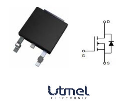
LM1084 Pinout

Figure 1. Pinout

Figure 2. Pin Descirption
LM1084 CAD Model

Figure 3. Symbol

Figure 4. Footprint

Figure 5. 3D Model
LM1084 Features
◆Three variants available: 3.3V, 5.0V and Adjustable Versions
◆Current Limiting and Thermal Protection
◆5A of Output Current
◆ Industrial Temperature Range −40˚C to 125˚C
◆Line Regulation 0.015% (typical)
◆ Load Regulation 0.1% (typical)
◆Available Package: TO-263 and TO-220
LM1084 Simplified Schematic

Figure 6. Simplified Schematic
Specifications
- TypeParameter
- Mount
In electronic components, the term "Mount" typically refers to the method or process of physically attaching or fixing a component onto a circuit board or other electronic device. This can involve soldering, adhesive bonding, or other techniques to secure the component in place. The mounting process is crucial for ensuring proper electrical connections and mechanical stability within the electronic system. Different components may have specific mounting requirements based on their size, shape, and function, and manufacturers provide guidelines for proper mounting procedures to ensure optimal performance and reliability of the electronic device.
Surface Mount - Package / Case
refers to the protective housing that encases an electronic component, providing mechanical support, electrical connections, and thermal management.
TO-263 - Number of Pins3
- Power Dissipation (Max)30W
- JESD-609 Code
The "JESD-609 Code" in electronic components refers to a standardized marking code that indicates the lead-free solder composition and finish of electronic components for compliance with environmental regulations.
e0 - Pbfree Code
The "Pbfree Code" parameter in electronic components refers to the code or marking used to indicate that the component is lead-free. Lead (Pb) is a toxic substance that has been widely used in electronic components for many years, but due to environmental concerns, there has been a shift towards lead-free alternatives. The Pbfree Code helps manufacturers and users easily identify components that do not contain lead, ensuring compliance with regulations and promoting environmentally friendly practices. It is important to pay attention to the Pbfree Code when selecting electronic components to ensure they meet the necessary requirements for lead-free applications.
no - Moisture Sensitivity Level (MSL)
Moisture Sensitivity Level (MSL) is a standardized rating that indicates the susceptibility of electronic components, particularly semiconductors, to moisture-induced damage during storage and the soldering process, defining the allowable exposure time to ambient conditions before they require special handling or baking to prevent failures
3 (168 Hours) - Number of Terminations3
- ECCN Code
An ECCN (Export Control Classification Number) is an alphanumeric code used by the U.S. Bureau of Industry and Security to identify and categorize electronic components and other dual-use items that may require an export license based on their technical characteristics and potential for military use.
EAR99 - Terminal Finish
Terminal Finish refers to the surface treatment applied to the terminals or leads of electronic components to enhance their performance and longevity. It can improve solderability, corrosion resistance, and overall reliability of the connection in electronic assemblies. Common finishes include nickel, gold, and tin, each possessing distinct properties suitable for various applications. The choice of terminal finish can significantly impact the durability and effectiveness of electronic devices.
Tin/Lead (Sn/Pb) - Max Operating Temperature
The Maximum Operating Temperature is the maximum body temperature at which the thermistor is designed to operate for extended periods of time with acceptable stability of its electrical characteristics.
125°C - Min Operating Temperature
The "Min Operating Temperature" parameter in electronic components refers to the lowest temperature at which the component is designed to operate effectively and reliably. This parameter is crucial for ensuring the proper functioning and longevity of the component, as operating below this temperature may lead to performance issues or even damage. Manufacturers specify the minimum operating temperature to provide guidance to users on the environmental conditions in which the component can safely operate. It is important to adhere to this parameter to prevent malfunctions and ensure the overall reliability of the electronic system.
-40°C - Terminal Position
In electronic components, the term "Terminal Position" refers to the physical location of the connection points on the component where external electrical connections can be made. These connection points, known as terminals, are typically used to attach wires, leads, or other components to the main body of the electronic component. The terminal position is important for ensuring proper connectivity and functionality of the component within a circuit. It is often specified in technical datasheets or component specifications to help designers and engineers understand how to properly integrate the component into their circuit designs.
SINGLE - Terminal Form
Occurring at or forming the end of a series, succession, or the like; closing; concluding.
GULL WING - Peak Reflow Temperature (Cel)
Peak Reflow Temperature (Cel) is a parameter that specifies the maximum temperature at which an electronic component can be exposed during the reflow soldering process. Reflow soldering is a common method used to attach electronic components to a circuit board. The Peak Reflow Temperature is crucial because it ensures that the component is not damaged or degraded during the soldering process. Exceeding the specified Peak Reflow Temperature can lead to issues such as component failure, reduced performance, or even permanent damage to the component. It is important for manufacturers and assemblers to adhere to the recommended Peak Reflow Temperature to ensure the reliability and functionality of the electronic components.
235 - Number of Functions1
- Terminal Pitch
The center distance from one pole to the next.
2.54mm - Current Rating
Current rating is the maximum current that a fuse will carry for an indefinite period without too much deterioration of the fuse element.
5A - Pin Count
a count of all of the component leads (or pins)
4 - Number of Outputs1
- Output Type
The "Output Type" parameter in electronic components refers to the type of signal or data that is produced by the component as an output. This parameter specifies the nature of the output signal, such as analog or digital, and can also include details about the voltage levels, current levels, frequency, and other characteristics of the output signal. Understanding the output type of a component is crucial for ensuring compatibility with other components in a circuit or system, as well as for determining how the output signal can be utilized or processed further. In summary, the output type parameter provides essential information about the nature of the signal that is generated by the electronic component as its output.
Fixed - Max Output Current
The maximum current that can be supplied to the load.
5A - Polarity
In electronic components, polarity refers to the orientation or direction in which the component must be connected in a circuit to function properly. Components such as diodes, capacitors, and LEDs have polarity markings to indicate which terminal should be connected to the positive or negative side of the circuit. Connecting a component with incorrect polarity can lead to malfunction or damage. It is important to pay attention to polarity markings and follow the manufacturer's instructions to ensure proper operation of electronic components.
Positive - Current - Output
Current - Output is a parameter in electronic components that refers to the maximum amount of current that can be delivered by the output of the component. It is a crucial specification as it determines the capability of the component to supply power to connected devices or circuits. The current output rating is typically specified in amperes (A) and is important for ensuring that the component can safely and effectively power the load it is connected to without overheating or failing. Designers and engineers must consider the current output rating when selecting components to ensure compatibility and reliable operation of the overall system.
1.5A - Quiescent Current
The quiescent current is defined as the current level in the amplifier when it is producing an output of zero.
5mA - Voltage - Output
Voltage - Output is a parameter that refers to the electrical potential difference between the output terminal or pin of an electronic component and a reference point, typically ground. It indicates the level of voltage that the component is capable of providing at its output under specified operating conditions. This parameter is crucial in determining the performance and functionality of the component in a circuit, as it directly affects the signal or power being delivered to other components or devices connected to the output. Engineers and designers use the voltage output specification to ensure compatibility and proper functioning of the component within the overall system.
3.3V - Output Voltage 1
Output Voltage 1 is a parameter commonly found in electronic components such as voltage regulators, power supplies, and amplifiers. It refers to the voltage level that is produced or delivered by the component at a specific output terminal or pin. This parameter is crucial for determining the performance and functionality of the component in a circuit. The specified output voltage should meet the requirements of the connected devices or components to ensure proper operation and compatibility. It is important to carefully consider and verify the output voltage 1 specification when selecting and using electronic components in a design or application.
3.3V - Min Input Voltage
The parameter "Min Input Voltage" in electronic components refers to the minimum voltage level that must be applied to the component for it to operate within its specified parameters. This value is crucial as providing a voltage below this minimum threshold may result in the component malfunctioning or not functioning at all. It is important to adhere to the specified minimum input voltage to ensure the proper operation and longevity of the electronic component. Failure to meet this requirement may lead to potential damage to the component or the overall system in which it is used.
2.6V - Max Input Voltage
Max Input Voltage refers to the maximum voltage level that an electronic component can safely handle without getting damaged. This parameter is crucial for ensuring the proper functioning and longevity of the component. Exceeding the specified maximum input voltage can lead to overheating, electrical breakdown, or permanent damage to the component. It is important to carefully adhere to the manufacturer's guidelines regarding the maximum input voltage to prevent any potential issues and maintain the reliability of the electronic device.
27V - Dropout Voltage
Dropout voltage is the input-to-output differential voltage at which the circuit ceases to regulate against further reductions in input voltage; this point occurs when the input voltage approaches the output voltage.
1.3V - Dropout Voltage1-Nom
Dropout Voltage1-Nom is a parameter commonly found in voltage regulators and power management ICs. It refers to the minimum voltage difference required between the input voltage and the output voltage for the regulator to maintain regulation. In other words, it is the minimum voltage drop that the regulator can handle while still providing a stable output voltage. This parameter is important to consider when designing power supply circuits to ensure that the regulator can operate within its specified voltage range and maintain proper regulation under varying load conditions.
1.3V - Voltage Tolerance-Max
Voltage Tolerance-Max is a parameter in electronic components that specifies the maximum allowable deviation from the rated voltage without causing damage or malfunction. It indicates the range within which the component can safely operate without being affected by voltage fluctuations. This parameter is crucial for ensuring the reliability and longevity of the component in various electrical systems. Manufacturers provide this specification to help users understand the limits within which the component can function properly and to prevent potential failures due to overvoltage conditions.
2% - Load Regulation-Max(%)
Load Regulation-Max(%) is a measure of how much the output voltage of a power supply or voltage regulator changes in response to variations in load current. It is expressed as a percentage of the nominal output voltage and indicates the maximum deviation from the set voltage when the load shifts from no load to full load. A lower value of load regulation signifies better performance, as it indicates that the output voltage remains stable under varying load conditions.
0.02% - Line Regulation-Max (%/V)
Line regulation refers to the ability of an electronic component, such as a voltage regulator, to maintain a stable output voltage despite variations in the input voltage. The parameter "Line Regulation-Max (%/V)" specifies the maximum percentage change in the output voltage for a given change in the input voltage. For example, if the Line Regulation-Max is 0.1%/V, it means that the output voltage will change by a maximum of 0.1% for every 1V change in the input voltage. A lower value for Line Regulation-Max indicates better performance and stability of the component in maintaining a consistent output voltage under varying input conditions. It is an important parameter to consider when designing or selecting electronic components for applications where voltage stability is critical.
0.006% - Height Seated (Max)
Height Seated (Max) is a parameter in electronic components that refers to the maximum allowable height of the component when it is properly seated or installed on a circuit board or within an enclosure. This specification is crucial for ensuring proper fit and alignment within the overall system design. Exceeding the maximum seated height can lead to mechanical interference, electrical shorts, or other issues that may impact the performance and reliability of the electronic device. Manufacturers provide this information to help designers and engineers select components that will fit within the designated space and function correctly in the intended application.
4.8mm - Radiation Hardening
Radiation hardening is the process of making electronic components and circuits resistant to damage or malfunction caused by high levels of ionizing radiation, especially for environments in outer space (especially beyond the low Earth orbit), around nuclear reactors and particle accelerators, or during nuclear accidents or nuclear warfare.
No - RoHS Status
RoHS means “Restriction of Certain Hazardous Substances” in the “Hazardous Substances Directive” in electrical and electronic equipment.
Non-RoHS Compliant
LM1084 Functional Diagram

Figure 7. Functional Diagram
LM1084 Power Dissipation Diagram

Figure 8. Power Dissipation Diagram
LM1084 Alternatives

Figure 9. Alternatives
How to use LM1084?
Using a LM1084 is as easy as using LM317 regulator because it have the same pin configuration. Also, LM1084 comes with three variants in which two types have fixed regulated output and one is adjustable regulator. As you can see in the below diagram, this LM1084 is in adjustable mode and you can vary the regulated output voltage by changing the value of resistor R1 and R2.

Figure 10.
In fixed type regulator of LM1084, the ADJ pin is replaced by GND (Ground) pin. Check the connections for fixed type regulator below:

Figure 11.
LM1084 Application Circuit

Figure 12. Application Circuit
LM1084 Applications
■Post Regulator for Switching DC/DC Conveter
■High Efficiency Linear Regulators
■Battery Charger
LM1084 Typical Applications
Figure 13. Battery Backup Regulated Supply

A regulated battery backup supply can be generated by using two fixed output voltage versions of the part. The top regulator supplies the Line voltage during normal operation, however when the input is not available, the second regulator derives power from the battery backup and regulates it to 5 V based on the LM1084-5.0. The diodes prevent the rails from back feeding into the supply and batteries.
Figure 14. Automatic Light control

A common street light control or automatic light control circuit is designed in Figure 25 based on the LM1084- ADJ. The photo transistor conducts in the presence of light and grounds the ADJ pin preventing the lamp from turning on. However, in the absence of light, the LM1084 regulates the voltage to 1.25V between OUT and ADJ, ensuring the lamp remains on.
Figure 15. Ripple Rejection Enhancement

A very simple ripple rejection circuit is shown in Figure 24 using the LM1084-ADJ. The capacitor C1 smooths out the ripple on the output by cleaning up the feedback path and preventing excess noise from feeding back into the regulator. Please remember XC1 should be approximately equal to R1 at the ripple frequency.
Figure 16. Generating Negative Supply voltage

A quick inverting output rail or negative output rail is shown in Figure using the LM1084 fixed output part. By tying the output to GND, the GND node is at a relatively more negative potential than the output. This is then interfaced to the negative application such as an operational amplifier or any other rail needing negative voltage.
Figure 17. Remote Sensing

Remote sensing is a method of compensating the output voltage to a very precise degree by sensing the output and feeding it back through the feedback. The circuit implementing this is shown in Figure 27 using the LM1084- ADJ. The output of the regulator is fed into a voltage follower to avoid any loading effects and the output of the op-amp is injected into the top of the feedback resistor network. This has the effect of modulating the voltage to a precise degree without additional loading on the output.
LM1084 Package

Figure 18. Package TO-263
LM1084 Manufacturer
Texas Instruments (TI) is an American technology company headquartered in Dallas, Texas, which designs and manufactures semiconductors and various integrated circuits, and sells them to electronic designers and manufacturers worldwide. It is one of the top 10 semiconductor companies in global sales. The company focuses on the development of analog chips and embedded processors, which account for more than 80% of its revenue. TI also produces TI digital light processing technology and educational technology products, including calculators, microcontrollers and multi-core processors. As of 2016, the company has 45,000 patents worldwide.
Datasheet PDF
- Datasheets :
1.How to search for LM1084 chip in Multisim?
There is no LM1084 in Multisim's component library. Most of the components in Multisim are universal or widely used (often by more manufacturers), and rarely include more special devices (because that will lead to a large increase in the development workload of the simulation component library, and the volume of the software will also be Very large)
2.The adjustable voltage regulator module needs 5A current, what chip can be used?
LM1084 is a low dropout output voltage adjustable voltage regulator chip, which can output 5A.
3,What is the minimum input voltage required for a 5V2A output with LM1084?
At 2A, generally between 0.8V and 1.2V.
 AOD482:circuit, pinout and specifications
11 March 2022339
 DS26LV32ATM:CMOS Receiver, Pinout, Datasheet
24 March 20221231
 A Comprehensive Guide to Fairchild 74ACTQ16245SSC Bus Transceiver
11 March 2024472
 LT3080 Low Dropout Regulator: Datasheet, Alternatives and Applications
25 October 20214961
 TPS54331DR Converter: Pinout, Alternatives, Datasheet
30 November 20235093
 Delving into the Technical Specifications of the Microchip PIC16C74B20PQ Microcontroller
29 February 2024137
 Advantech Corp 96MPXE-2.1-16M36: A Discontinued Skylake Microprocessor Module
11 March 20243627
![HT7333 How to use a HT7333 IC?[Video]](https://res.utmel.com/Images/Article/882d6c87-9c81-4515-b682-29cdfa70cf1a.png) HT7333 How to use a HT7333 IC?[Video]
HT7333 How to use a HT7333 IC?[Video]18 April 20226420
![A Guide to AVR Microcontroller [PDF]](https://res.utmel.com/Images/Article/0c3aa30d-e2d7-48f0-99c3-1b176aa33832.jpg) A Guide to AVR Microcontroller [PDF]
A Guide to AVR Microcontroller [PDF]15 October 20259722
 SiC Power Conversion Devices at High Ambient Temperatures
14 March 20232682
 What is Chiplet?
17 November 20214188
 Introduction to Temperature Sensors
24 October 20259955
 An Overview of Linear Integrated Circuits
23 October 202512367
 Foxconn Announces Investment of $9 Billion to Build a Chip Factory in Saudi Arabia
15 March 20227227
 General PCB Layout Design Guidelines for RF and Digital-to-Analog Circuits
20 January 202213970
 Buffer Amplifier | Operating Principle, Advantages, and Applications
21 July 202510262
Texas Instruments
In Stock
United States
China
Canada
Japan
Russia
Germany
United Kingdom
Singapore
Italy
Hong Kong(China)
Taiwan(China)
France
Korea
Mexico
Netherlands
Malaysia
Austria
Spain
Switzerland
Poland
Thailand
Vietnam
India
United Arab Emirates
Afghanistan
Åland Islands
Albania
Algeria
American Samoa
Andorra
Angola
Anguilla
Antigua & Barbuda
Argentina
Armenia
Aruba
Australia
Azerbaijan
Bahamas
Bahrain
Bangladesh
Barbados
Belarus
Belgium
Belize
Benin
Bermuda
Bhutan
Bolivia
Bonaire, Sint Eustatius and Saba
Bosnia & Herzegovina
Botswana
Brazil
British Indian Ocean Territory
British Virgin Islands
Brunei
Bulgaria
Burkina Faso
Burundi
Cabo Verde
Cambodia
Cameroon
Cayman Islands
Central African Republic
Chad
Chile
Christmas Island
Cocos (Keeling) Islands
Colombia
Comoros
Congo
Congo (DRC)
Cook Islands
Costa Rica
Côte d’Ivoire
Croatia
Cuba
Curaçao
Cyprus
Czechia
Denmark
Djibouti
Dominica
Dominican Republic
Ecuador
Egypt
El Salvador
Equatorial Guinea
Eritrea
Estonia
Eswatini
Ethiopia
Falkland Islands
Faroe Islands
Fiji
Finland
French Guiana
French Polynesia
Gabon
Gambia
Georgia
Ghana
Gibraltar
Greece
Greenland
Grenada
Guadeloupe
Guam
Guatemala
Guernsey
Guinea
Guinea-Bissau
Guyana
Haiti
Honduras
Hungary
Iceland
Indonesia
Iran
Iraq
Ireland
Isle of Man
Israel
Jamaica
Jersey
Jordan
Kazakhstan
Kenya
Kiribati
Kosovo
Kuwait
Kyrgyzstan
Laos
Latvia
Lebanon
Lesotho
Liberia
Libya
Liechtenstein
Lithuania
Luxembourg
Macao(China)
Madagascar
Malawi
Maldives
Mali
Malta
Marshall Islands
Martinique
Mauritania
Mauritius
Mayotte
Micronesia
Moldova
Monaco
Mongolia
Montenegro
Montserrat
Morocco
Mozambique
Myanmar
Namibia
Nauru
Nepal
New Caledonia
New Zealand
Nicaragua
Niger
Nigeria
Niue
Norfolk Island
North Korea
North Macedonia
Northern Mariana Islands
Norway
Oman
Pakistan
Palau
Palestinian Authority
Panama
Papua New Guinea
Paraguay
Peru
Philippines
Pitcairn Islands
Portugal
Puerto Rico
Qatar
Réunion
Romania
Rwanda
Samoa
San Marino
São Tomé & Príncipe
Saudi Arabia
Senegal
Serbia
Seychelles
Sierra Leone
Sint Maarten
Slovakia
Slovenia
Solomon Islands
Somalia
South Africa
South Sudan
Sri Lanka
St Helena, Ascension, Tristan da Cunha
St. Barthélemy
St. Kitts & Nevis
St. Lucia
St. Martin
St. Pierre & Miquelon
St. Vincent & Grenadines
Sudan
Suriname
Svalbard & Jan Mayen
Sweden
Syria
Tajikistan
Tanzania
Timor-Leste
Togo
Tokelau
Tonga
Trinidad & Tobago
Tunisia
Turkey
Turkmenistan
Turks & Caicos Islands
Tuvalu
U.S. Outlying Islands
U.S. Virgin Islands
Uganda
Ukraine
Uruguay
Uzbekistan
Vanuatu
Vatican City
Venezuela
Wallis & Futuna
Yemen
Zambia
Zimbabwe
![TPS767D301PWPR]() TPS767D301PWPR
TPS767D301PWPRTexas Instruments
![LP2988AIMM-3.3]() LP2988AIMM-3.3
LP2988AIMM-3.3Texas Instruments
![LMS1587CSX-ADJ]() LMS1587CSX-ADJ
LMS1587CSX-ADJTexas Instruments
![LP3962ESX-2.5]() LP3962ESX-2.5
LP3962ESX-2.5Texas Instruments
![LP2967ITPX-1833/NOPB]() LP2967ITPX-1833/NOPB
LP2967ITPX-1833/NOPBTexas Instruments
![LP2951CMX/NOPB]() LP2951CMX/NOPB
LP2951CMX/NOPBTexas Instruments
![LM1117MPX-3.3/NOPB]() LM1117MPX-3.3/NOPB
LM1117MPX-3.3/NOPBTexas Instruments
![LP2985IM5-3.3/NOPB]() LP2985IM5-3.3/NOPB
LP2985IM5-3.3/NOPBTexas Instruments
![LM2937IMP-5.0/NOPB]() LM2937IMP-5.0/NOPB
LM2937IMP-5.0/NOPBTexas Instruments
![LP2951ACMM/NOPB]() LP2951ACMM/NOPB
LP2951ACMM/NOPBTexas Instruments


