

 Product
 Brand
Brand Articles
 Tools
Tools
TPS5430DDAR Converter: Features, Applications and Datasheet

8 Terminals 8-Pin TPS5430 DC DC Voltage Regulator SWITCHING REGULATOR 1 Outputs 500kHz Tape & Reel (TR) 8-PowerSOIC (0.154, 3.90mm Width)
Unit Price: $0.791494
Ext Price: $0.79


8 Terminals 8-Pin TPS5430 DC DC Voltage Regulator SWITCHING REGULATOR 1 Outputs 500kHz Tape & Reel (TR) 8-PowerSOIC (0.154, 3.90mm Width)
With Texas Instruments' step-down TPS5430DDAR DC to DC converter, you can change the voltage on your devices. This article will introduce its features, applications and datasheet.
TPS5430DDAR Description
With Texas Instruments' step-down TPS5430DDAR DC to DC converter, you can change the voltage on your devices. The single output of this converter has a maximum current output of 3 A. Use voltages between 5.5 and 36 volts while using this item. This is the pinnacle of power control, with an output voltage adjustable from 1.22 to 31 V. The efficiency of this converter is 95%. The frequency of its switching regulator is 600 kHz. In order to facilitate efficient mounting and secure transportation, this component will be sent in tape and reel packaging. The operational temperature range for this converter is -40 °C to 125 °C.
TPS5430DDAR Features
High Efficiency to 95% Wide Input Voltage Range: to 3-A Continuous (4-A Peak) Output Current Made possible by 110-m
A MOSFET switch integrated into one
Large Adjustable Output Voltage Range: 1.22 V to 1.5% Initial Accuracy
Minimizes External Parts Count Through Internal Compensation
500 kHz fixed switching frequency
For Tiny Filter Dimensions Enhanced Line Regulation and Transient Reaction via Input Voltage Feed Forward Technology
Protected by Thermal Shutdown to 125°C Operating Junction Temperature Range and Over Current Limiting
A Small Thermally Enhanced 8-Pin SOIC PowerPADTM Package is available.
Specifications
- TypeParameter
- Factory Lead Time16 Weeks
- Mount
In electronic components, the term "Mount" typically refers to the method or process of physically attaching or fixing a component onto a circuit board or other electronic device. This can involve soldering, adhesive bonding, or other techniques to secure the component in place. The mounting process is crucial for ensuring proper electrical connections and mechanical stability within the electronic system. Different components may have specific mounting requirements based on their size, shape, and function, and manufacturers provide guidelines for proper mounting procedures to ensure optimal performance and reliability of the electronic device.
Surface Mount - Mounting Type
The "Mounting Type" in electronic components refers to the method used to attach or connect a component to a circuit board or other substrate, such as through-hole, surface-mount, or panel mount.
Surface Mount - Package / Case
refers to the protective housing that encases an electronic component, providing mechanical support, electrical connections, and thermal management.
8-PowerSOIC (0.154, 3.90mm Width) - Number of Pins8
- Weight70.590313mg
- Voltage - Input (Nom)12V
- Operating Temperature
The operating temperature is the range of ambient temperature within which a power supply, or any other electrical equipment, operate in. This ranges from a minimum operating temperature, to a peak or maximum operating temperature, outside which, the power supply may fail.
-40°C~125°C TJ - Packaging
Semiconductor package is a carrier / shell used to contain and cover one or more semiconductor components or integrated circuits. The material of the shell can be metal, plastic, glass or ceramic.
Tape & Reel (TR) - JESD-609 Code
The "JESD-609 Code" in electronic components refers to a standardized marking code that indicates the lead-free solder composition and finish of electronic components for compliance with environmental regulations.
e4 - Pbfree Code
The "Pbfree Code" parameter in electronic components refers to the code or marking used to indicate that the component is lead-free. Lead (Pb) is a toxic substance that has been widely used in electronic components for many years, but due to environmental concerns, there has been a shift towards lead-free alternatives. The Pbfree Code helps manufacturers and users easily identify components that do not contain lead, ensuring compliance with regulations and promoting environmentally friendly practices. It is important to pay attention to the Pbfree Code when selecting electronic components to ensure they meet the necessary requirements for lead-free applications.
yes - Part Status
Parts can have many statuses as they progress through the configuration, analysis, review, and approval stages.
ACTIVE (Last Updated: 3 days ago) - Moisture Sensitivity Level (MSL)
Moisture Sensitivity Level (MSL) is a standardized rating that indicates the susceptibility of electronic components, particularly semiconductors, to moisture-induced damage during storage and the soldering process, defining the allowable exposure time to ambient conditions before they require special handling or baking to prevent failures
1 (Unlimited) - Number of Terminations8
- ECCN Code
An ECCN (Export Control Classification Number) is an alphanumeric code used by the U.S. Bureau of Industry and Security to identify and categorize electronic components and other dual-use items that may require an export license based on their technical characteristics and potential for military use.
EAR99 - Terminal Finish
Terminal Finish refers to the surface treatment applied to the terminals or leads of electronic components to enhance their performance and longevity. It can improve solderability, corrosion resistance, and overall reliability of the connection in electronic assemblies. Common finishes include nickel, gold, and tin, each possessing distinct properties suitable for various applications. The choice of terminal finish can significantly impact the durability and effectiveness of electronic devices.
Nickel/Palladium/Gold (Ni/Pd/Au) - Voltage - Supply
Voltage - Supply refers to the range of voltage levels that an electronic component or circuit is designed to operate with. It indicates the minimum and maximum supply voltage that can be applied for the device to function properly. Providing supply voltages outside this range can lead to malfunction, damage, or reduced performance. This parameter is critical for ensuring compatibility between different components in a circuit.
36V - Terminal Position
In electronic components, the term "Terminal Position" refers to the physical location of the connection points on the component where external electrical connections can be made. These connection points, known as terminals, are typically used to attach wires, leads, or other components to the main body of the electronic component. The terminal position is important for ensuring proper connectivity and functionality of the component within a circuit. It is often specified in technical datasheets or component specifications to help designers and engineers understand how to properly integrate the component into their circuit designs.
DUAL - Terminal Form
Occurring at or forming the end of a series, succession, or the like; closing; concluding.
GULL WING - Peak Reflow Temperature (Cel)
Peak Reflow Temperature (Cel) is a parameter that specifies the maximum temperature at which an electronic component can be exposed during the reflow soldering process. Reflow soldering is a common method used to attach electronic components to a circuit board. The Peak Reflow Temperature is crucial because it ensures that the component is not damaged or degraded during the soldering process. Exceeding the specified Peak Reflow Temperature can lead to issues such as component failure, reduced performance, or even permanent damage to the component. It is important for manufacturers and assemblers to adhere to the recommended Peak Reflow Temperature to ensure the reliability and functionality of the electronic components.
260 - Base Part Number
The "Base Part Number" (BPN) in electronic components serves a similar purpose to the "Base Product Number." It refers to the primary identifier for a component that captures the essential characteristics shared by a group of similar components. The BPN provides a fundamental way to reference a family or series of components without specifying all the variations and specific details.
TPS5430 - Function
The parameter "Function" in electronic components refers to the specific role or purpose that the component serves within an electronic circuit. It defines how the component interacts with other elements, influences the flow of electrical signals, and contributes to the overall behavior of the system. Functions can include amplification, signal processing, switching, filtering, and energy storage, among others. Understanding the function of each component is essential for designing effective and efficient electronic systems.
Step-Down - Number of Outputs1
- Efficiency
Efficiency in electronic components refers to the ratio of useful output energy or power to the input energy or power. It is a measure of how effectively a component converts input energy into output energy without wasting any energy in the process. Higher efficiency indicates that the component is more effective in performing its intended function while minimizing energy losses. Efficiency is an important parameter in electronic components such as power supplies, amplifiers, and motors, as it directly impacts the overall performance and energy consumption of the system. Manufacturers often specify the efficiency rating of their components to help users understand how efficiently the component operates under different conditions.
95 % - Output Type
The "Output Type" parameter in electronic components refers to the type of signal or data that is produced by the component as an output. This parameter specifies the nature of the output signal, such as analog or digital, and can also include details about the voltage levels, current levels, frequency, and other characteristics of the output signal. Understanding the output type of a component is crucial for ensuring compatibility with other components in a circuit or system, as well as for determining how the output signal can be utilized or processed further. In summary, the output type parameter provides essential information about the nature of the signal that is generated by the electronic component as its output.
Adjustable - Max Supply Voltage
In general, the absolute maximum common-mode voltage is VEE-0.3V and VCC+0.3V, but for products without a protection element at the VCC side, voltages up to the absolute maximum rated supply voltage (i.e. VEE+36V) can be supplied, regardless of supply voltage.
36V - Analog IC - Other Type
Analog IC - Other Type is a parameter used to categorize electronic components that are integrated circuits (ICs) designed for analog signal processing but do not fall into more specific subcategories such as amplifiers, comparators, or voltage regulators. These ICs may include specialized analog functions such as analog-to-digital converters (ADCs), digital-to-analog converters (DACs), voltage references, or signal conditioning circuits. They are typically used in various applications where precise analog signal processing is required, such as in audio equipment, instrumentation, communication systems, and industrial control systems. Manufacturers provide detailed specifications for these components to help engineers select the most suitable IC for their specific design requirements.
SWITCHING REGULATOR - Current - Output (Max)
Current - Output (Max) is a parameter in electronic components that specifies the maximum amount of current that the component can deliver at its output. This parameter is crucial in determining the capability of the component to supply power to other parts of a circuit or system. It is typically measured in amperes (A) and helps in ensuring that the component can handle the required current without getting damaged or causing malfunctions. Designers and engineers use this specification to select components that can meet the current requirements of their circuits and prevent overloading or overheating issues.
3A - Output Configuration
Output Configuration in electronic components refers to the arrangement or setup of the output pins or terminals of a device. It defines how the output signals are structured and how they interact with external circuits or devices. The output configuration can determine the functionality and compatibility of the component in a circuit design. Common types of output configurations include single-ended, differential, open-drain, and push-pull configurations, each serving different purposes and applications in electronic systems. Understanding the output configuration of a component is crucial for proper integration and operation within a circuit.
Positive - Quiescent Current
The quiescent current is defined as the current level in the amplifier when it is producing an output of zero.
3mA - Max Output Voltage
The maximum output voltage refers to the dynamic area beyond which the output is saturated in the positive or negative direction, and is limited according to the load resistance value.
31V - Voltage - Output
Voltage - Output is a parameter that refers to the electrical potential difference between the output terminal or pin of an electronic component and a reference point, typically ground. It indicates the level of voltage that the component is capable of providing at its output under specified operating conditions. This parameter is crucial in determining the performance and functionality of the component in a circuit, as it directly affects the signal or power being delivered to other components or devices connected to the output. Engineers and designers use the voltage output specification to ensure compatibility and proper functioning of the component within the overall system.
31V - Voltage - Output (Min/Fixed)
Voltage - Output (Min/Fixed) refers to the minimum fixed output voltage level that an electronic component, such as a voltage regulator or power supply, is designed to provide under specified load conditions. This parameter ensures that the device consistently delivers a reliable voltage that meets the requirements of the connected circuits or components. It is critical for applications where stable and predictable voltage is necessary for proper operation.
1.221V - Topology
In the context of electronic components, "topology" refers to the arrangement or configuration of the components within a circuit or system. It defines how the components are connected to each other and how signals flow between them. The choice of topology can significantly impact the performance, efficiency, and functionality of the electronic system. Common topologies include series, parallel, star, mesh, and hybrid configurations, each with its own advantages and limitations. Designers carefully select the appropriate topology based on the specific requirements of the circuit to achieve the desired performance and functionality.
Buck - Control Mode
In electronic components, "Control Mode" refers to the method or mode of operation used to regulate or control the behavior of the component. This parameter determines how the component responds to input signals or commands to achieve the desired output. The control mode can vary depending on the specific component and its intended function, such as voltage regulation, current limiting, or frequency modulation. Understanding the control mode of an electronic component is crucial for proper integration and operation within a circuit or system.
VOLTAGE-MODE - Frequency - Switching
"Frequency - Switching" in electronic components refers to the rate at which a device, such as a transistor or switching regulator, turns on and off during operation. This parameter is crucial in determining the efficiency and performance of power converters, oscillators, and other circuits that rely on rapid switching. Higher switching frequencies typically allow for smaller component sizes but may require more advanced design considerations to manage heat and electromagnetic interference.
500kHz - Control Technique
In electronic components, "Control Technique" refers to the method or approach used to regulate and manage the operation of the component. This parameter is crucial in determining how the component functions within a circuit or system. Different control techniques can include analog control, digital control, pulse-width modulation (PWM), and various feedback mechanisms. The choice of control technique can impact the performance, efficiency, and overall functionality of the electronic component. It is important to select the appropriate control technique based on the specific requirements and characteristics of the application in which the component will be used.
PULSE WIDTH MODULATION - Synchronous Rectifier
Synchronous rectification is a technique for improving the efficiency of rectification by replacing diodes with actively controlled switches, usually power MOSFETs or power bipolar junction transistors (BJT).
No - Min Output Voltage
Min Output Voltage refers to the lowest voltage level that an electronic component, such as a voltage regulator or power supply, can provide reliably under specified conditions. It indicates the minimum threshold required for proper operation of connected devices. Operating below this voltage may lead to device malfunction or failure to operate as intended.
1.22V - Max Duty Cycle
Max Duty Cycle refers to the maximum percentage of time that an electronic component, such as a switch or a power supply, can be in an "on" state during a defined time period. It is an important parameter in pulse-width modulated (PWM) systems and helps determine how often a device can operate without overheating or sustaining damage. By specifying the maximum duty cycle, manufacturers provide guidance on the safe operational limits of the component, ensuring reliability and efficiency in various applications.
89 % - Max Junction Temperature (Tj)
Max Junction Temperature (Tj) refers to the maximum allowable temperature at the junction of a semiconductor device, such as a transistor or integrated circuit. It is a critical parameter that influences the performance, reliability, and lifespan of the component. Exceeding this temperature can lead to thermal runaway, breakdown, or permanent damage to the device. Proper thermal management is essential to ensure the junction temperature remains within safe operating limits during device operation.
125°C - Voltage - Supply (Min)
Voltage - Supply (Min) is a parameter in electronic components that specifies the minimum voltage required for the component to operate within its specified performance range. This parameter indicates the lowest voltage level that can be safely applied to the component without causing malfunctions or damage. It is crucial to ensure that the supply voltage provided to the component is equal to or higher than the specified minimum voltage to guarantee proper functionality and reliability. Failure to meet this requirement may result in erratic behavior, reduced performance, or even permanent damage to the component.
5.5V - Height1.7mm
- Length4.89mm
- Width3.9mm
- Thickness
Thickness in electronic components refers to the measurement of how thick a particular material or layer is within the component structure. It can pertain to various aspects, such as the thickness of a substrate, a dielectric layer, or conductive traces. This parameter is crucial as it impacts the electrical, mechanical, and thermal properties of the component, influencing its performance and reliability in electronic circuits.
1.48mm - RoHS Status
RoHS means “Restriction of Certain Hazardous Substances” in the “Hazardous Substances Directive” in electrical and electronic equipment.
ROHS3 Compliant - Lead Free
Lead Free is a term used to describe electronic components that do not contain lead as part of their composition. Lead is a toxic material that can have harmful effects on human health and the environment, so the electronics industry has been moving towards lead-free components to reduce these risks. Lead-free components are typically made using alternative materials such as silver, copper, and tin. Manufacturers must comply with regulations such as the Restriction of Hazardous Substances (RoHS) directive to ensure that their products are lead-free and environmentally friendly.
Lead Free
TPS5430DDAR CAD Model
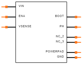
Symbol
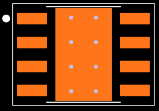
Footprint
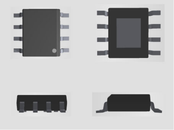
3D Model
TPS5430DDAR Alternatives
Part Number | Description | Manufacturer |
TPS5430QDDARQ1 | Automotive 5.5V to 36V, 500kHz Fixed Frequency 3A Buck Converter 8-SO PowerPAD -40 to 125 | Texas Instruments |
TPS5430DDA | 5.5V to 36V Input, 3A, 500kHz Step-Down Converter 8-SO PowerPAD -40 to 125 | Texas Instruments |
TPS5430DDAG4 | 5.5V to 36V Input, 3A, 500kHz Step-Down Converter 8-SO PowerPAD -40 to 125 | Texas Instruments |
TPS5430DDARG4 | 5.5V to 36V Input, 3A, 500kHz Step-Down Converter 8-SO PowerPAD -40 to 125 | Texas Instruments |
TPS5430DDAR Applications
Consumer: Set-top Box, DVD, LCD Displays Industrial and Car Audio Power Supplies Battery Chargers, High Power LED Supply 12V/24V Distributed Power Systems
TPS5430DDAR Manufacturer
Texas Instruments is a global semiconductor company that designs, manufactures, tests and sells analog and embedded processing chips for various markets. It was founded in 1930 as Geophysical Service Incorporated, a company that provided seismic exploration services for the oil industry. In 1951, it changed its name to Texas Instruments and entered the field of electronics, producing the first commercial silicon transistor in 1954. Since then, it has been a pioneer in many fields, such as integrated circuits, calculators, microprocessors, digital signal processors, and wireless communication. Today, it has more than 80,000 products that help its customers efficiently manage power, accurately sense and transmit data, and provide the core control or processing in their designs. Its products go into markets such as industrial, automotive, personal electronics, communications equipment and enterprise systems. It has a vision to create a better world by making electronics more affordable through semiconductors, and a mission to engineer progress by innovating and creating differentiated analog and embedded processing products.
Parts with Similar Specs
- ImagePart NumberManufacturerPackage / CaseNumber of PinsNumber of OutputsMax Output CurrentFrequency - SwitchingInput Voltage-NomMin Output VoltageOutput VoltageMax Output VoltageVoltage - Output (Max)EfficiencyView Compare
![TPS5430DDAR]()
TPS5430DDAR
8-PowerSOIC (0.154, 3.90mm Width)
8
1
3 A
500kHz
12 V
1.22 V
31 V
31 V
32.04V
95 %
![TPS5431DDA]()
8-PowerSOIC (0.154, 3.90mm Width)
8
1
3 A
-
12 V
1.285 V
1.285 V
37 V
37V
90 %
![LM22676MRE-ADJ/NOPB]()
8-PowerSOIC (0.154, 3.90mm Width)
8
1
3 A
500kHz
12 V
1.22 V
20 V
20 V
20.47V
95 %
![LM22676MR-ADJ/NOPB]()
8-SOIC (0.154, 3.90mm Width)
8
1
3 A
370kHz
-
1.235 V
-
21.62 V
-
-
![LV5980MC-AH]()
8-PowerSOIC (0.154, 3.90mm Width)
8
1
3 A
-
12 V
1.285 V
1.285 V
37 V
37V
90 %


Datasheet PDF
- PCN Design/Specification :
- PCN Assembly/Origin :
What is the negative voltage of TPS5430?
With a 15-V input voltage and a –5-V output voltage, the TPS5430 is conceived as an inverting buck-boost converter in this configuration. The semiconductors are idealized and other component losses are disregarded in the simplified presentation of the design equations.
 An In-depth Look at LTC7003IMSE#TRPBF Gate Driver: Features, Applications, and Reference Designs
06 March 2024401
 Unveiling the NXP LPC3141/3143 Microcontroller: A Detailed Overview
29 February 2024234
 RH850/F1L Microcontroller for Automotive Body Applications: Datasheet Overview
29 February 2024317
 Exploring the Cypress MB91520 Series: 32-bit FR81S Microcontroller for Automotive Devices
29 February 2024208
 P600A Diode: P600A Datasheet, Equivalent, Pinout
19 April 20223011
 TIP125 Darlington Transistor: Datasheet PDF, Pinout, Circuit
15 February 20226396
 SB230 Diode: Application, Pinout, Datasheet
30 July 20211060
 WS2812B Addressable RGB LED: Datasheet, Pinout and Applications
10 September 202133596
 An Analysis of Current-Source Inverters Using High-Frequency WBG Switches
09 May 20235022
 What is 4G Router?
27 September 20217648
 MLCC: Applications and Future Development
20 December 202110310
 What is an Accelerometer Sensor?
20 April 202112622
 HDMI RF Modulators: Architecture, Setup, Types, and Commercial Applications
18 May 2026576
 What is An Optoisolator?
09 January 20218574
 Introduction to Photonic Integrated Circuits and PIC Technology
22 October 202515376
 What is a USB Type-C Connector?
28 October 20256730
Texas Instruments
In Stock: 5530
Minimum: 1 Multiples: 1
Qty
Unit Price
Ext Price
1
$0.791494
$0.79
10
$0.746692
$7.47
100
$0.704427
$70.44
500
$0.664553
$332.28
1000
$0.626937
$626.94
Not the price you want? Send RFQ Now and we'll contact you ASAP.
Inquire for More Quantity
![LM2574HVMX-3.3]() LM2574HVMX-3.3
LM2574HVMX-3.3Texas Instruments
![LM25574MTX]() LM25574MTX
LM25574MTXTexas Instruments
![LM2577MX-ADJ]() LM2577MX-ADJ
LM2577MX-ADJTexas Instruments
![TLV62565DBVR]() TLV62565DBVR
TLV62565DBVRTexas Instruments
![LM25011MY/NOPB]() LM25011MY/NOPB
LM25011MY/NOPBTexas Instruments
![LM2575T-5.0/NOPB]() LM2575T-5.0/NOPB
LM2575T-5.0/NOPBTexas Instruments
![MC33063ADR]() MC33063ADR
MC33063ADRTexas Instruments
![LM2675MX-ADJ/NOPB]() LM2675MX-ADJ/NOPB
LM2675MX-ADJ/NOPBTexas Instruments
![LM2574N-5.0/NOPB]() LM2574N-5.0/NOPB
LM2574N-5.0/NOPBTexas Instruments
![LM2576SX-5.0/NOPB]() LM2576SX-5.0/NOPB
LM2576SX-5.0/NOPBTexas Instruments


