

 Product
 Brand
Brand Articles
 Tools
Tools
Humanoid Robot BOM Breakdown: Every Chip Inside a Physical AI Platform
If you are sourcing silicon for a full-size humanoid robot, the number that matters most is 40. A 40-joint reference platform — 28 body joints plus two 6-DoF hands — contains roughly 40 three-phase motor drive stages, 80 absolute magnetic encoders, and more than 50 microcontrollers just to handle motion. This article breaks down every IC category inside that machine, counts the parts, and names the representative part families you will encounter when building the bill of materials.
Before diving into the silicon, a brief cost context: actuators (motors, gears, and their drive electronics) account for 40–60% of the total BOM, sensing and perception systems 10–20%, compute and control 10–15%, with batteries and structure making up the remainder (McKinsey & Company, April 2026). A teardown of the Unitree G1 base model published by Zhongyou Securities (April 2026) placed the actuator share above 60% of a total BOM of approximately 41,600 RMB. These percentages are now widely cited. The gap this article fills is the part-level detail underneath them.
Reference platform definition
Throughout this article, the unit counts apply to a single composite reference humanoid: approximately 170 cm tall, 55–60 kg, 40 actuated joints (28 body joints plus two hands at 6 DoF each), a 48 V main bus, and 2–5 hours of battery runtime. This is a representative engineering construct, not a teardown of any single commercial product, inspired by accessible architectures like Berkeley Humanoid Lite[2].
How many motor control ICs sit inside one humanoid robot?
The drive electronics inside each joint form the highest silicon count in the machine. A single joint actuator requires a three-phase gate driver, a power stage (six switches configured as three half-bridges), two or three current-sense channels, and bulk and decoupling capacitance. Multiply that by 40, then add the two hands — each finger joint carrying its own miniature drive stage — and the total becomes clear.
Per-joint BOM (one actuator):
1 × three-phase gate driver or integrated smart gate driver
6 × power MOSFETs or 1 × integrated GaN power stage (3 half-bridges)
2–3 × current sense amplifiers or Hall-effect current sensors
1 × isolation component where the architecture requires it (digital isolator or isolated gate driver)
1 × bulk capacitor bank plus high-frequency decoupling capacitors
1 × local motion control MCU (shared or per-joint, counted here for completeness)
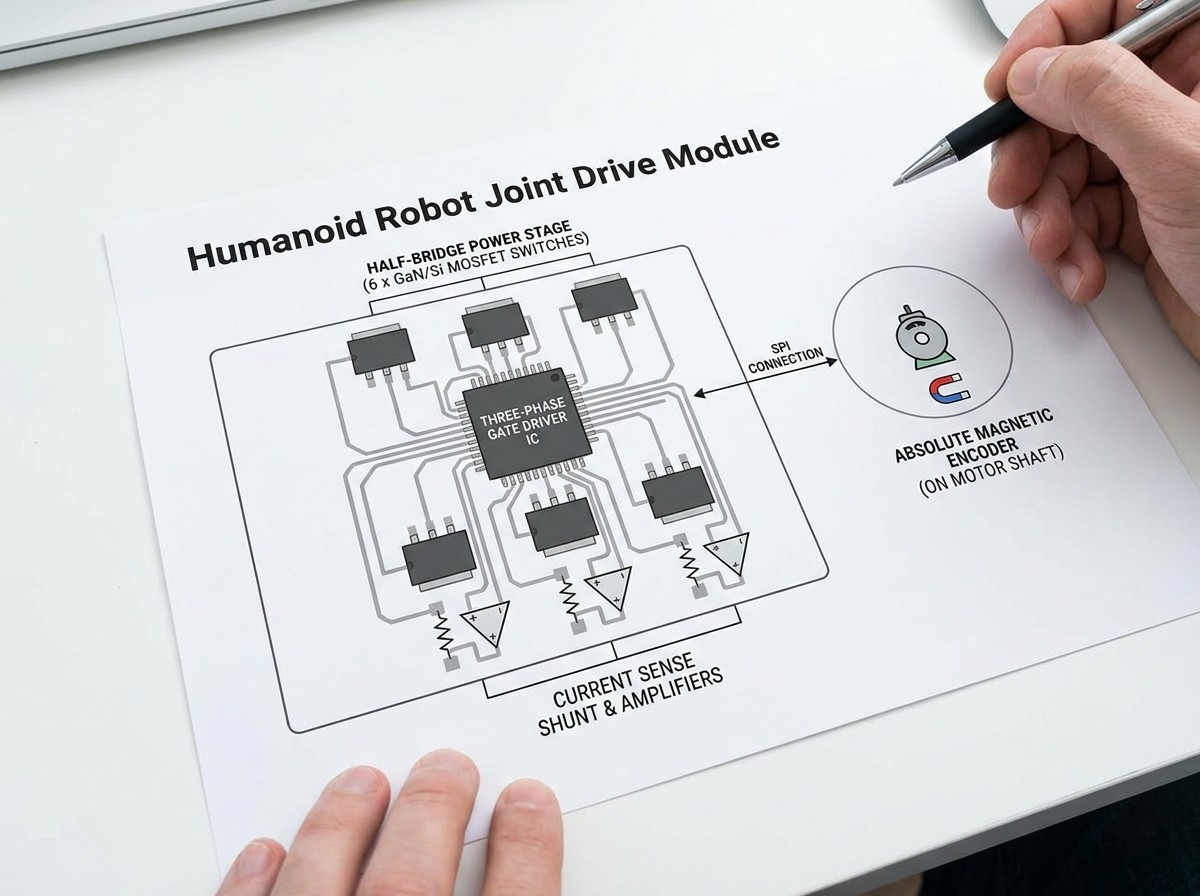
Representative part families:
Gate driver: DRV8323 (Texas Instruments), L9904 (STMicroelectronics), or integrated devices like TMC9660 (ADI/Trinamic), which embeds FOC control, gate drive, and a buck converter in a single IC.
Power stage: For Si MOSFET half-bridges, NTMFS5C604NL (onsemi) or similar 60–100 V N-channel MOSFETs in DFN5×6 packages. For designs migrating to GaN, EPC23104 (EPC) integrates gate driver, level shifter, and GaN FETs into a single chip rated at 100 V. High-frequency switching at 40–100 kHz, cited in EPC application documentation[3] (August 2025), allows electrolytic capacitors to be replaced by ceramic equivalents, shrinking the drive PCB to fit inside a 32 mm diameter joint housing.
Current sensing: INA240 (TI) for shunt-based measurement with high common-mode rejection; for contactless sensing, Hall-effect ICs such as TMCS1100 (TI) at sensitivities around 44 mV/A.
Isolation: ISO6721 (TI) digital isolator or ISO5852S for reinforced gate drive isolation where the architecture demands it.
Total quantity derivation: 40 joints × 6 power switches = 240 discrete MOSFETs (or 40 integrated GaN power stages) for body joints alone. Add two 6-DoF hands, each finger joint miniaturized but requiring its own half-bridge set, and the total rises to approximately 280–300 power-stage switch positions across the reference platform. This is the line item that dominates the power semiconductor BOM.
Sourcing difficulty: Watch. GaN power stages in small packages remain supply-constrained in 2026, and automotive-qualified gate drivers frequently carry minimum order quantities (MOQs) designed for Tier 1 production volumes. Distributors that support small-quantity purchases and offer cross-brand alternates become essential for prototype and pilot builds. For a deeper look at power semiconductor lead times, see Power Semiconductors Shortage Outlook 2026.
Why do serious designs run two encoders per joint?
Each joint in a high-performance humanoid carries two absolute position sensors: one on the motor shaft for electronic commutation and Field-Oriented Control (FOC), and a second on the output side after the reducer to compensate for backlash and gear compliance. The motor-side encoder runs a fast control loop; the output-side encoder provides the ground-truth joint angle.
Encoder type comparison:
| Technology | Resolution | Vibration Tolerance | Cost (Volume) | Typical Interface |
|---|---|---|---|---|
| Magnetic (Hall/AMR) | 12–17-bit | Excellent | Under $1–$3 | SPI, SSI, BiSS-C |
| Optical (reflective) | 18–21-bit | Moderate | Higher | BiSS-C, RS-485 |
| Capacitive | 12–16-bit | Good | Low | SPI, I²C |
Magnetic absolute encoders have become the default choice in humanoid joints. They withstand the shock and vibration of bipedal locomotion, cost under a dollar in volume, and fit into the tight axial space between motor and reducer. Representative parts include AS5047P (ams-OSRAM, 14-bit, SPI), MA702 (MPS, 12-bit, SPI), and the ADMT4000 from Analog Devices[4], a single-chip absolute magnetic encoder that retains position data through power cycles without requiring a re-zeroing routine — a critical feature when a robot powers down mid-operation and must recover its posture without calibration moves.
Count: 40 joints × 2 encoders per joint = 80 absolute magnetic encoders on the reference platform.
Sourcing difficulty: Watch. The AS5047 family has seen periodic allocation in 2025–2026. Robotics startups report 16–26 week lead times on some encoder part numbers, and substituting a different magnetic encoder often requires a PCB respin because of pinout and register-map differences.
What sits between the AI brain and the joint-level silicon?
The motion control architecture splits into three tiers, with real-time control processors distributed across the machine.
Tier 1 — Central motion controller (“cerebellum”): One or two high-performance MCUs or SoCs that run whole-body kinematics, trajectory planning, and balance control at loop rates typically in the 1–5 kHz range. Representative parts: STM32H743 (ST), AM64x Sitara (TI), or the HPM6E00 series (HPMicro), which integrates EtherCAT, CAN FD, Gigabit Ethernet, and TSN switching on one die.
Tier 2 — Joint-level or limb-level MCU: Each joint or limb group contains a microcontroller that closes the current loop and FOC algorithm. In distributed architectures, one MCU per joint is typical. The STM32G4 series (ST) — specifically the STM32G431 — is the most frequently cited representative in the STMicroelectronics Humanoid Robot Reference Guide[1], running FOC loops at 20–50 kHz on a Cortex-M4 core. Other viable families include TMS320F28004x (TI C2000), i.MX RT series (NXP), and the RISC‑V‑based HPM5xxx series.
Tier 3 — Integrated drive MCU: A growing number of designs embed the control core inside the gate driver IC itself, as in the TMC9660, which includes a dedicated FOC engine and runs 100 kHz control loops without requiring external MCU software. This reduces BOM count but sacrifices firmware flexibility.
Total MCU count: A full-size humanoid contains approximately 56 MCU chips dedicated to motor control alone (per EEWORLD, May 2026 analysis), a figure consistent with the reference platform: 40 joint-level MCUs, plus an additional ~16 distributed across dexterous hands, battery management, balance sensing, and communication gateways.
Sourcing difficulty: Watch to Constrained. STM32G4 and high-end C2000 parts remain in high demand across industrial and automotive markets. Lead times fluctuate between 8 and 26 weeks depending on the exact variant. For a current assessment of MCU lead-time risk and cross-brand alternatives, see MCU Power Management Availability Forecast 2026.
What silicon does the AI compute stack require?
The central compute module — the “brain” — runs vision-language-action models, sensor fusion, and high-level decision-making. In 2026, two representative SoC examples illustrate the range: the Rockchip RK3588 (an 8-core ARM SoC found in platforms like the Unitree G1) and the NVIDIA Jetson AGX Orin module, which delivers 200–275 TOPS for transformer-based policy models.

Supporting silicon around the SoC:
LPDDR memory: LPDDR4X or LPDDR5, typically 8–32 GB, in PoP (package-on-package) or discrete configuration. The DRAM price cycle compressed memory cost significantly through early 2025, but pricing has tightened since mid-2025 as suppliers shifted capacity to HBM for data center AI (see 2026 Memory Strategic Sourcing Tactics).
Storage: eMMC 5.1 (64–256 GB) or NVMe SSD for logging and model storage. Representative: Kingston EMMC or Samsung PM991 NVMe.
PMIC set: Multiple rails — core, I/O, memory, and analog — typically managed by a multi-channel PMIC such as the NXP PCA9450 (designed for i.MX/RK platforms) or a discrete set of LDOs and DC-DC converters.
Thermal management: Active cooling (fan + heatsink) for >15 W TDP modules, with thermal pads or heat pipes connecting the SoC to the chassis structure.
Sourcing difficulty: Watch. Jetson modules have been on extended lead time periodically since the 2023–2024 AI boom. The RK3588 is available through Chinese distributor channels with shorter lead times, but availability outside Asia can be inconsistent for small-volume buyers.
How does the robot feel balance, force, and touch?
Inertial sensing (balance):
Bipedal balance depends on the bias instability specification, not the noise density usually quoted in consumer datasheets. A typical humanoid uses one industrial-grade IMU in the torso or pelvis, plus consumer-grade 6-axis parts in each limb for local orientation feedback. Representative families: the BNO085 (CEVA/Hillcrest, 9-axis with on-chip sensor fusion) for mid-tier integration, and the ADIS16470 (Analog Devices, industrial-grade, 12°/hr bias instability) where precision matters.
Count: 1 torso IMU + 4 limb IMUs = 5 IMUs minimum.
Sourcing difficulty: Easy. Industrial IMUs carry higher unit prices but are generally available from distribution.
Force and torque sensing:
Six-axis force/torque sensors at the wrists and ankles require high-resolution delta-sigma ADCs to digitize strain-gauge bridges. The ADS122C04 (TI, 24-bit, I²C) is a representative front-end IC. A precision voltage reference — e.g., REF5025 (TI, 2.5 V, 3 ppm/°C drift) — stabilizes the bridge excitation voltage. In 2026, six-axis sensor costs have fallen approximately 60% year-over-year, from 20,000–30,000 RMB to 5,000–8,000 RMB, driven by manufacturing scale (TMTPost, June 2026).
Count: 4 six-axis sensors (two wrists, two ankles), each with its own ADC and reference.
Sourcing difficulty: Constrained. The sensor bodies themselves — especially ATI or Sunrise Instruments models — carry 12–20 week lead times. The ADC and reference ICs are standard catalog parts and less constrained, but the mechanical sensor assembly remains the bottleneck.
Tactile sensing:
Dexterous hands now ship palm-mounted and fingertip tactile arrays capable of resolving forces in the single-gram range. The sensing modality varies — piezoelectric films, capacitive arrays, and MEMS-based pressure sensors all appear in current platforms. Piezoelectric sensors generate a voltage proportional to applied force, making them effective for detecting contact transients and slip, though they measure dynamic change rather than static load. The interface IC is typically a multi-channel analog front-end or a dedicated capacitive-to-digital converter like the FDC2214 (TI, 28-bit resolution for capacitive sensing arrays).
Humanoid Robot Body Parts Explained From Head To Toe! | Anatomy Of A Robot
Sourcing difficulty: Watch. Commercial tactile arrays remain a development item; many robotics teams fabricate their own sensor skins while sourcing the interface ICs as standard catalog parts.
What is inside the battery and power path?
A 48 V main bus, typically derived from a 13S or 14S lithium-ion pack, requires a full battery management and power conversion chain.
Battery management ICs:
Battery monitor / AFE: BQ76952 (TI, 3–16S stackable) for pack voltage and cell monitoring, with integrated coulomb counting.
Fuel gauge: BQ34Z100-G1 (TI) or equivalent for state-of-charge tracking.
Protection: Discrete back-to-back MOSFETs controlled by the AFE's protection logic, or a dedicated protector IC.
Precharge circuit: A relay or MOSFET to limit inrush current when connecting the pack to the 48 V bus.
Power conversion chain:
48 V to intermediate rails: High-power DC-DC converters step the 48 V bus down to 12 V and 5 V intermediate rails. Representative converter families: LTC3895 (Analog Devices, high-voltage buck controller) or LM5116 (TI).
Point-of-load regulation: Post-switching, a chain of LDOs and small buck converters generates the 3.3 V, 1.8 V, 1.2 V, and core voltage rails required by the compute module, MCUs, and sensors. Rail count: typically 8–12 distinct voltage levels across the robot.
eFuses: Hot-swap controllers and eFuses (e.g., TPS25947, TI) protect each downstream rail from overcurrent.
Sourcing difficulty: Easy for catalog parts; Watch for automotive-grade AFEs. Standard BMS ICs are widely available through distribution. However, functional-safety-qualified (ASIL-D) battery monitors from NXP or Infineon carry the same small-quantity constraints as other automotive parts.
What connects the nerves of the machine?
The in-robot network is hierarchical:
Joint bus: EtherCAT or TSN (Time-Sensitive Networking) Ethernet runs between the central motion controller and distributed joint nodes. EtherCAT slave controllers like the ET1100 (Beckhoff) or integrated EtherCAT MCUs handle the real-time data frames. CAN FD serves as a lower-cost alternative or legacy fallback on less critical limbs.
Physical layer ICs: Each EtherCAT or Ethernet node requires a PHY — representative examples include the DP83867 (TI, Gigabit) or LAN8742 (Microchip, 10/100).
Vision data bus: High-resolution camera data from the head unit travels to the central compute via a high-speed serial interface — GMSL (Maxim/Analog Devices) or FPD-Link (TI) serializer/deserializer pairs, with the DS90UB954-Q1 (TI) deserializer hub cited in ADI's application documentation.
Wireless: Wi-Fi 6/6E (e.g., CYW5557x, Infineon) for OTA updates and telemetry, plus BLE 5.3 for low-power connectivity.
Count: 1 PHY per joint node, plus 2–4 serializers for camera links, one wireless module.
Sourcing difficulty: Watch. EtherCAT slave controller ICs are primarily sourced from Beckhoff and a small number of licensees; alternatives exist but require re-certification of the EtherCAT stack.
What safety silicon do most prototype builds forget?
Functional safety architecture is the subsystem most frequently under-scoped in first prototype builds. A production humanoid requires:
Safety MCU or supervisor: A dedicated MCU (e.g., TMS570, TI Hercules safety series, or an ASIL-B-rated MCU) that monitors joint states, motor currents, and communications integrity, independent of the main motion controller.
Safe Torque Off (STO): Hardware circuitry that physically disconnects gate drive signals from the power stage when a safety event is detected — not a software-controlled disable.
Watchdog: External watchdog timer IC that resets the safety MCU if its firmware hangs.
Isolation: Reinforced digital isolators between the safety domain and the high-voltage power domain.
Limit switches: Physical switches at the edges of each joint's mechanical workspace. As demonstrated in robotics actuator system testing, limit switches cut power when the robot exceeds its range of motion, preventing self-destruction if the software motion planner fails.
Sourcing difficulty: Easy for standard safety MCUs; Constrained for automotive-certified parts at small volumes.
Consolidated BOM Summary Table
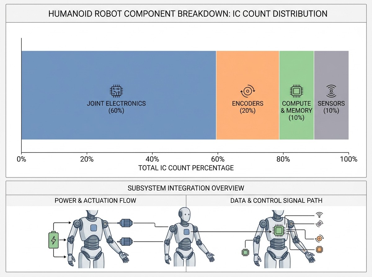
| Subsystem | IC Category | Qty per Robot | Sourcing Difficulty |
|---|---|---|---|
| Joint Actuator Drive | Three-phase gate driver | 40 | Watch |
| Joint Actuator Drive | GaN integrated power stage (or 6× discrete MOSFETs) | 40 (or 240 discrete) | Watch |
| Joint Actuator Drive | Current sense amplifier | 80–120 | Easy |
| Joint Actuator Drive | Digital isolator | 40 (where required) | Easy |
| Joint Position Feedback | Absolute magnetic encoder | 80 | Watch |
| Motion Control | Joint-level MCU (FOC) | 40 | Watch to Constrained |
| Motion Control | Central motion controller MCU | 1–2 | Watch |
| Central Compute | AI SoC/module | 1 | Watch |
| Central Compute | LPDDR (configured with SoC) | 1–2 packages | Constrained |
| Central Compute | eMMC / NVMe storage | 1–2 | Easy |
| Central Compute | PMIC | 1–2 | Easy |
| Inertial Sensing | Industrial-grade IMU | 1 | Easy |
| Inertial Sensing | Consumer 6-axis IMU | 4 | Easy |
| Force/Torque Sensing | 6-axis F/T sensor assembly | 4 | Constrained |
| Force/Torque Sensing | Delta-sigma ADC + precision reference | 4 sets | Easy |
| Tactile Sensing | Capacitive/resistive AFE | 2–4 | Watch |
| Battery Management | Battery monitor AFE | 1 | Easy (standard); Constrained (ASIL-D) |
| Battery Management | Fuel gauge | 1 | Easy |
| Power Conversion | DC-DC converters and LDOs | 8–12 rails | Easy |
| Power Conversion | eFuse / hot-swap controller | 4–8 | Easy |
| Communication | EtherCAT slave controller / PHY | 40+ | Watch |
| Communication | Wi-Fi 6 / BLE module | 1 | Easy |
| Functional Safety | Safety MCU + watchdog | 1–2 | Constrained |
What actually blocks small-batch builds?
Three constraints separate a five-unit prototype run from a 500-unit pilot production build:
1. Automotive-grade part MOQs. Many gate drivers, safety MCUs, and position sensors are qualified to AEC-Q100 and sold primarily to Tier 1 automotive suppliers. A robotics startup requesting 50 units of an automotive gate driver IC often faces a 2,000-unit minimum order line — or an outright refusal to quote. Distributors that aggregate demand and hold buffer stock across multiple customers, with parametric search tools to find pin-compatible alternates across integrated circuits ICs, bridge this gap. The ability to source one reel of STM32G4 MCUs, 50 pieces of an AS5047 encoder, and a handful of TMC9660 smart gate drivers from a single supplier — without negotiating separate MOQ waivers with each manufacturer — is what enables prototype velocity.
2. Encoder and force-sensor lead times. Magnetic encoder lead times of 16–26 weeks are frequently cited in 2025–2026 robotics sourcing discussions. Six-axis force/torque sensors carry similar lead times due to the manual calibration step. The procurement strategy that works is: order sensors at the same time as the first PCB spin, not after. If the encoder you designed in goes on allocation, having cross-reference data for the MPS MA702, AMS AS5047, and ADI ADMT4000 on hand prevents a three-month stall while a layout engineer re-spins the joint-drive board.
3. The inventory gap. Large franchised distributors optimize their inventory for high-volume, repetitive orders — the 100,000-unit annual blanket purchase orders from automotive and industrial. A robotics startup ordering 50 to 500 pieces of an IC hits a gap: too large for prototyping distributors, too small for volume allocation. Platforms that maintain catalog stock of robotics-relevant ICs — gate drivers, magnetic encoders, current-sense amplifiers, BMS AFEs — with no minimum order quantity per line, and that display real-time stock visibility and datasheets on every part page, let a team order exactly what the BOM demands without building inventory they cannot afford to carry.
What to ignore in the current narrative
Three patterns in the 2025–2026 humanoid coverage are worth filtering out when making IC-level sourcing decisions:
“The BOM will drop 90% by 2028.” The documented cost compression in sensors and actuators is real (6-axis sensors dropped 60% in one year), but semiconductor cost curves follow a different physics than machined mechanical parts. ICs that are already cost-optimized for automotive scale — gate drivers, automotive MCUs — will not see another order-of-magnitude reduction.
“One SoC runs everything.” The distributed-architecture consensus (40+ local MCUs plus a central AI compute module) reflects real-time control physics, not a temporary engineering inefficiency. FOC loop closure at 20–50 kHz cannot be centralized across a 170 cm robot body without unacceptable latency.
“All parts are commodity; just spec generics.” Encoder ICs, safety MCUs, and EtherCAT slave controllers are source-constrained markets with limited second-source options. Designing a generic footprint that accepts multiple manufacturers’ pinouts remains the single most effective hardware decision for supply chain resilience.
Frequently Asked Questions
How many ICs are inside a typical humanoid robot?
Counting only the semiconductor-level components (MCUs, gate drivers, encoders, power switches, sensing ICs, communication ICs, and power management), a 40-joint reference humanoid contains approximately 400–500 discrete ICs, not including the SoC's internal transistor count.
What is the highest-volume IC category?
Power-stage switches: 240–300 discrete MOSFETs or 40 integrated GaN power stages for body joints and hands. Magnetic encoders are second at roughly 80 units (two per joint).
Why not use one central drive amplifier for all joints?
Running 40 high-current, three-phase motor cables from a central drive rack to distributed joints adds kilograms of copper, generates EMI that couples into sensor cables, and introduces latency that degrades FOC loop bandwidth. Distributed drive electronics inside each joint housing is the industry-standard architecture.
Is GaN replacing silicon MOSFETs in all humanoid joints?
GaN is the design direction for compact joints where PCB area is the primary constraint, but silicon MOSFETs remain widely used in larger shoulder and hip joints where thermal mass and board space are less restricted. The selection is per-joint, not per-robot.
What is the single most constrained part type for small-batch builds?
Automotive-qualified MCUs (e.g., TMS570 safety series, ST SPC58) and six-axis force/torque sensor assemblies. Both categories combine long lead times with MOQs that are misaligned with the unit volumes of prototype and pilot robotics builds.
Does the BOM count include redundancy?
The counts in this article are for a single-string functional architecture. Production humanoids designed for environments with functional safety requirements (ISO 13849 or ISO 10218) may include dual-channel safety MCUs, redundant encoder paths, and additional isolation — adding 20–40 ICs to the total.
References
Humanoid Robot Reference Guide — STMicroelectronics
Demonstrating Berkeley Humanoid Lite: An Open-source, Accessible, and Customizable 3D-printed Humanoid Robot — University of California, Berkeley
深入关节内部:GaN 集成电路如何实现超紧凑的人形机器人电机驱动器 — EPC Co
ADI人形机器人解决方案 — Analog Devices
 UTMEL
UTMEL
We are the professional distributor of electronic components, providing a large variety of products to save you a lot of time, effort, and cost with our efficient self-customized service. careful order preparation fast delivery service
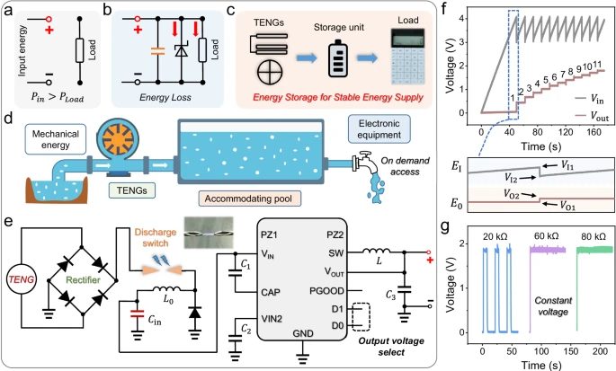 Improving the Energy Conversion Efficiency of Triboelectric NanogeneratorsSaumitra Jagdale19 November 20243212
There is a huge growth in demand for self-sustaining electronic devices, as the traditional power-generating devices fail in remote and harsh environments due to the periodic requirement of battery changes. Also, these devices are frequency specific; some work only in high frequency and some in low frequency. Triboelectric nanogenerators (TENGs) provide a promising solution by efficiently converting mechanical energy into electricity as they are versatile, compact, and cheap, making them a popular choice.
Read More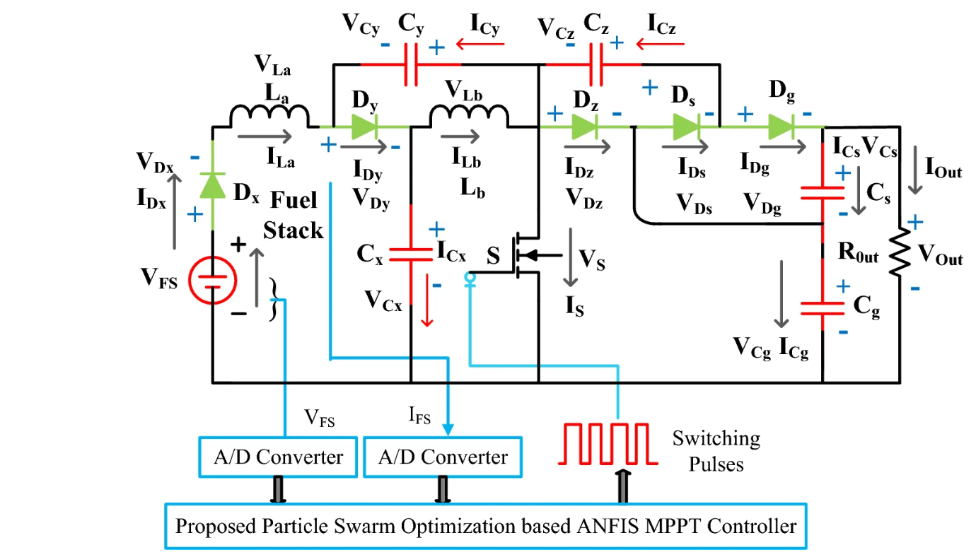 Methodologies for Increasing Efficiency of Fuel Stack Technology for Energy GenerationSaumitra Jagdale19 November 20243066
Presently, power companies are moving towards renewable energy systems. Conventional energy sources are more expensive because they require a vast network to be maintained and huge human resources. Also, they harm the environment by releasing several harmful gases. As the industry’s focus shifts toward renewable energy sources, energy systems powered by Proton Exchange Membrane Fuel Stacks (PEMFS) are gaining traction.
Read More VSC Light Meaning, Causes, and Step-by-Step DiagnosticsUTMEL19 May 20262634
A VSC (Vehicle Stability Control) light indicates the system is disabled, often as a fail-safe triggered by unrelated engine faults like a loose gas cap. While the stability system prevents lateral skidding, it shuts down when sensor data is unreliable. Proper diagnosis requires an ABS-capable OBD2 scanner. Resolving the root engine code, checking wheel speed sensors, or performing a zero-point calibration usually restores system function.
Read More What JEDEC JEP203 and JEP204 Actually Change for SiC Qualification Engineers and Component BuyersUTMEL29 July 2026388
Summary: When JEDEC published JEP203 and JEP204 on June 3, 2026[1], most coverage treated them as an announcement. They are better understood as the first shared language the silicon carbide industry has had for two problems that have quietly consumed engineering hours since the first commercial SiC MOSFETs shipped: short-circuit evaluation that produces numbers you can compare across suppliers, and a consolidated reference of stress procedures so qualification engineers stop reinventing test plans from scratch. This article explains what changes on Monday morning and what to ask suppliers for now.
Read More 2nm vs 3nm Chips: What the Latest Process Nodes Mean for PerformanceUTMEL19 August 2026990
The shift from 3nm to 2nm process nodes marks a fundamental change in transistor architecture, moving from FinFET to Gate-All-Around (GAA) nanosheets. This transition delivers meaningful improvements in performance, power, and density, but also introduces new challenges like SRAM scaling limits, thermal density, and backside power delivery. The article compares TSMC, Samsung, and Intel approaches, offering a practical decision framework for engineering teams.
Read More
Subscribe to Utmel !
![Z50-020]() Z50-020
Z50-020Harwin Inc.
![AD-1522-1-CRIMPING-TOOL]() AD-1522-1-CRIMPING-TOOL
AD-1522-1-CRIMPING-TOOLTE Connectivity Raychem Cable Protection
![0639000400]() 0639000400
0639000400Molex
![2266188-1]() 2266188-1
2266188-1TE Application Tooling
![6061]() 6061
6061Keystone Electronics
![47-10290]() 47-10290
47-10290Amphenol RF
![P25-1223]() P25-1223
P25-1223Harwin Inc.
![09990000852]() 09990000852
09990000852HARTING
![1212734]() 1212734
1212734Phoenix Contact
![09990000501]() 09990000501
09990000501HARTING


