

 Product
 Brand
Brand Articles
 Tools
Tools
AD8066ARZ-R7 Precision Amplifier: Technical Specifications and Applications

2 Channels 30mA per Channel 3pA 100 dB Instrumentational OP Amps 0.000006μA 5V~24V ±2.5V~12V AD8066 8 Pins 8-SOIC (0.154, 3.90mm Width)


2 Channels 30mA per Channel 3pA 100 dB Instrumentational OP Amps 0.000006μA 5V~24V ±2.5V~12V AD8066 8 Pins 8-SOIC (0.154, 3.90mm Width)
The AD8066ARZ-R7 precision amplifier offers 145 MHz bandwidth, low noise, and rail-to-rail output, ideal for industrial, medical, and communication applications.
Product Introduction
The AD8066ARZ-R7 stands out as a high-performance precision amplifier tailored for demanding applications. Its wide supply voltage range, spanning from 5 V to 24 V, ensures compatibility with various systems. You will appreciate its remarkable speed, featuring a 145 MHz bandwidth and a 180 V/µs slew rate, which makes it ideal for fast signal processing. Designed to operate reliably across temperatures from -40°C to +85°C, it delivers consistent performance in challenging environments. Its dual voltage feedback design further enhances versatility, making it a preferred choice for industries requiring low noise and precision.
Performance Overview of the AD8066ARZ-R7
Key Technical Specifications of the AD8066ARZ
The AD8066ARZ-R7 delivers exceptional precision and performance, making it a standout choice among operational amplifiers. Its technical specifications highlight its capabilities in demanding applications. Below is a summary of its key parameters:
| Specification | Value |
|---|---|
| Input Offset Voltage (Vos) | 400 µV |
| Slew Rate (SR) | 160 V/µs |
| Gain Bandwidth Product (GBP) | 145 MHz |
| Common Mode Rejection Ratio (CMRR) | 100 dB |
| Power Supply Rejection Ratio (PSRR) | 100 dB |
| Input Voltage Noise Density (en) | 7 nV/√Hz |
| Input Bias Current (Ib) | 6 pA |
These specifications demonstrate the amplifier's ability to handle high-speed and low-noise operations. The 145 MHz gain bandwidth product ensures excellent signal fidelity, while the 160 V/µs slew rate supports rapid signal transitions. The low input voltage noise density of 7 nV/√Hz makes it ideal for applications requiring high precision.
Unique Features and Innovations in the AD8066ARZ-R7
The AD8066ARZ-R7 incorporates several innovative features that set it apart from other operational amplifiers. One of its standout characteristics is its rail-to-rail output, which maximizes the dynamic range and ensures optimal performance in low-voltage systems. Its dual voltage feedback design enhances stability and accuracy, making it a reliable choice for precision applications.
Another key innovation is its low input bias current of just 6 pA. This feature minimizes errors in high-impedance circuits, ensuring accurate signal processing. The amplifier also boasts a high common mode rejection ratio (CMRR) and power supply rejection ratio (PSRR), both rated at 100 dB. These attributes make it highly resistant to noise and fluctuations in power supply, ensuring consistent performance.
The AD8066ARZ-R7's ability to operate across a wide temperature range (-40°C to +85°C) further enhances its versatility. Whether you're working in industrial automation, medical devices, or communication systems, this high-performance dual op amp adapts to your needs.
Benefits of Low Noise and High-Speed Operation
Low noise and high-speed operation are critical for many applications, and the AD8066ARZ-R7 excels in both areas. Its low input voltage noise density of 7 nV/√Hz ensures that even the smallest signals are amplified without distortion. This makes it an excellent choice for sensitive applications like medical imaging and test equipment.
The amplifier's high slew rate of 160 V/µs and 145 MHz gain bandwidth product enable it to handle rapid signal changes with ease. This ensures accurate signal reproduction in high-frequency applications, such as communication systems and networking. The rail-to-rail output further enhances its performance by providing a full dynamic range, even in low-voltage environments.
By combining low noise, high speed, and rail-to-rail capabilities, the AD8066ARZ-R7 delivers unmatched precision and reliability. Whether you're designing a voltage feedback amplifier for industrial control systems or a portable docking station, this operational amplifier meets your requirements.
Applications of the AD8066ARZ-R7
Use in Industrial Automation and Control Systems
The AD8066ARZ-R7 plays a vital role in industrial automation and control systems. You can rely on its high-speed operation and low noise performance to ensure precise signal processing in demanding environments. Its wide supply voltage range allows it to integrate seamlessly into various industrial setups, from factory automation to robotics.
In control systems, the amplifier's precision application ensures accurate feedback and error correction. For example, in motor control systems, it processes signals from sensors to maintain optimal performance. Its ability to operate reliably across a wide temperature range makes it suitable for harsh industrial conditions. By using the AD8066ARZ-R7, you can achieve greater efficiency and reliability in your automation projects.
Role in Medical Devices and Ultrasound Transducers
Medical devices demand high precision and reliability, and the AD8066ARZ-R7 delivers on both fronts. Its low input voltage noise density ensures that even the smallest signals are amplified accurately. This feature is particularly important in devices like ultrasound transducers, where clear and precise signal processing is critical.
You can also use the AD8066ARZ in other medical applications, such as patient monitoring systems and imaging equipment. Its high slew rate and gain bandwidth product enable it to handle rapid signal changes, ensuring accurate data capture and processing. Additionally, its low input bias current minimizes errors in high-impedance circuits, making it ideal for sensitive medical instruments. With the AD8066ARZ-R7, you can design medical devices that meet the highest standards of performance and reliability.
Applications in Communication Systems and Networking
In communication systems and networking, speed and accuracy are paramount. The AD8066ARZ-R7 excels in these areas, making it a valuable component in high-frequency applications. Its 145 MHz gain bandwidth product and 160 V/µs slew rate allow it to process signals quickly and accurately, ensuring seamless data transmission.
You can use the AD8066ARZ in various networking devices, such as routers, switches, and signal repeaters. Its rail-to-rail output maximizes the dynamic range, even in low-voltage systems, enhancing overall performance. The amplifier's high common mode rejection ratio and power supply rejection ratio ensure consistent operation, even in noisy environments. By incorporating the AD8066ARZ-R7 into your communication systems, you can achieve faster and more reliable data processing.
Relevance in Test and Measurement Equipment
Test and measurement equipment demands precision and reliability. The AD8066ARZ-R7 meets these requirements with its low noise and high-speed performance. You can use it to amplify weak signals without distortion, ensuring accurate readings in sensitive instruments. Its low input voltage noise density of 7 nV/√Hz makes it ideal for applications where signal clarity is critical.
This amplifier's high slew rate of 160 V/µs allows it to handle rapid signal changes effectively. For example, in oscilloscopes or spectrum analyzers, it ensures that fast-moving signals are captured with precision. Its rail-to-rail output further enhances its performance by providing a full dynamic range, even in low-voltage systems.
The AD8066ARZ-R7 also excels in environments with fluctuating power supplies. Its high power supply rejection ratio (PSRR) of 100 dB ensures consistent performance, even in noisy conditions. This makes it a reliable choice for test and measurement equipment used in industrial and laboratory settings. By integrating this amplifier into your designs, you can achieve greater accuracy and dependability in your instruments.
Automotive and Portable Docking Station Applications
In automotive systems, the AD8066ARZ-R7 plays a crucial role in ensuring precise signal processing. Its ability to operate across a wide temperature range (-40°C to +85°C) makes it suitable for harsh automotive environments. You can use it in applications like engine control units, where accurate signal amplification is essential for optimal performance.
The amplifier's low input bias current of 6 pA minimizes errors in high-impedance circuits. This feature is particularly useful in automotive sensors, where precision is critical. Its high common mode rejection ratio (CMRR) of 100 dB ensures that noise from the vehicle's electrical system does not interfere with signal processing.
For portable docking stations, the AD8066ARZ-R7 offers high-speed operation and low power consumption. Its 145 MHz gain bandwidth product ensures seamless data transmission, while its rail-to-rail output maximizes the dynamic range. Whether you're designing a docking station for smartphones or laptops, this amplifier provides the performance and reliability you need.
Comparison with Alternatives
Advantages Over Competing Precision Amplifiers
When comparing the AD8066ARZ-R7 to other precision amplifiers, its unique features give it a distinct edge. Its rail-to-rail output ensures maximum dynamic range, making it ideal for applications requiring high signal fidelity. The low input offset voltage minimizes errors, ensuring accurate amplification even in sensitive tasks. With a high slew rate, the AD8066ARZ-R7 processes dynamic signals quickly, making it suitable for fast-changing environments. Its wide supply voltage range, operating from a single supply up to ±15V, enhances versatility across various systems. Additionally, its low noise design makes it perfect for applications where signal clarity is critical.
| Feature | Advantage Description |
|---|---|
| Rail-to-Rail Output | Provides maximum output range for improved performance. |
| Low Input Offset Voltage | Minimizes errors and ensures accuracy in amplification tasks. |
| High Slew Rate | Achieves fast response times for dynamic signal processing. |
| Wide Supply Voltage Range | Operates from a single supply up to ±15V, enhancing versatility. |
| Low Noise | Designed to minimize noise, making it suitable for sensitive applications. |
Cost-Effectiveness and Value Proposition of the AD8066ARZ
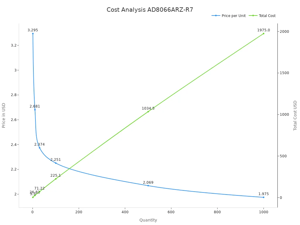
The AD8066ARZ-R7 offers exceptional value for its price. Whether you need a single unit or bulk quantities, its cost-effectiveness stands out. For instance, purchasing 10 units reduces the price per unit significantly compared to buying just one. Larger quantities, such as 500 or 1000 units, further lower the cost per unit, making it an economical choice for large-scale projects. This pricing structure ensures you get high performance without exceeding your budget.
| Quantity | Price (USD) | Total (USD) |
|---|---|---|
| 1 | $3.295 | $3.30 |
| 10 | $2.681 | $26.81 |
| 30 | $2.374 | $71.22 |
| 100 | $2.251 | $225.10 |
| 500 | $2.069 | $1,034.50 |
| 1000 | $1.975 | $1,975.00 |
Scenarios Where the AD8066ARZ-R7 Excels
The AD8066ARZ-R7 shines in scenarios requiring precision and reliability. Its rail-to-rail output maximizes performance in applications like signal conditioning and data acquisition systems. The low input offset voltage ensures accuracy in instrumentation amplifiers, where precision is crucial. Its high slew rate supports fast signal processing, making it ideal for dynamic environments. The wide supply voltage range enhances compatibility across diverse systems, while its low noise design makes it perfect for sensitive applications.
| Feature | Description |
|---|---|
| Rail-to-Rail Output | Maximizes output range for improved performance in various applications. |
| Low Input Offset Voltage | Minimizes errors and ensures accuracy in amplification tasks. |
| High Slew Rate | Achieves fast response times for dynamic signal processing. |
| Wide Supply Voltage Range | Operates from a single supply up to ±15V, enhancing versatility. |
| Low Noise | Designed to minimize noise, making it suitable for sensitive applications. |
| Application | Description |
|---|---|
| Signal Conditioning | Ideal for conditioning signals in measurement applications. |
| Data Acquisition Systems | Utilized in systems requiring accurate and precise signal acquisition. |
| Instrumentation | Suitable for use in instrumentation amplifiers where low noise and accuracy are crucial. |
Practical Considerations for Using the AD8066ARZ-R7
Tips for Implementation and Integration
When integrating the AD8066ARZ-R7 into your design, following proper implementation strategies ensures optimal performance. Here are some key tips to guide you:
Connect the IN- and IN+ pins to the input signals you want to amplify.
Attach the V- and V+ pins to the correct power supplies based on your system's voltage requirements.
Use the OFFSET pin for offset nulling if your application demands precise signal adjustments.
The OUT pin delivers the amplified output voltage, which you can route to the next stage of your circuit.
Refer to the datasheet for detailed instructions and recommended configurations.
For enhanced performance, consider pairing the AD8066ARZ-R7 with complementary amplifiers like the AD8500.
By following these steps, you can ensure smooth integration and reliable operation in your project.
Design Considerations for Optimal Performance
To achieve the best results with the AD8066ARZ-R7, you need to focus on key design aspects. Start by selecting the appropriate power supply voltage within the amplifier's range of 5 V to 24 V. This ensures compatibility with your system. Place decoupling capacitors near the power pins to reduce noise and stabilize the supply voltage.
Minimize the length of signal paths to avoid unwanted interference. Use high-quality resistors and capacitors to maintain signal integrity. If your application involves high-frequency signals, consider shielding sensitive components to prevent electromagnetic interference. For applications requiring high precision, offset nulling can help eliminate small errors in the output signal.
Common Challenges and How to Address Them
You may encounter challenges when using the AD8066ARZ-R7, but understanding them helps you find solutions. Noise interference is a common issue, especially in high-frequency applications. To address this, use proper grounding techniques and shield your circuit from external noise sources.
Another challenge involves offset errors in high-precision tasks. You can resolve this by utilizing the OFFSET pin for nulling adjustments. If your design experiences instability, check the placement of decoupling capacitors and ensure the power supply voltage remains within the recommended range.
By anticipating these challenges and applying the right solutions, you can maximize the performance and reliability of the AD8066ARZ-R7 in your designs.
The AD8066ARZ-R7 offers unmatched precision, making it a reliable choice for your projects. Its high-speed performance and low noise design ensure accurate signal processing across diverse applications. Whether you work in industrial automation, medical devices, or automotive systems, this amplifier adapts to your needs. Its wide supply voltage range and robust temperature tolerance make it versatile and dependable. Explore the AD8066ARZ-R7 to elevate your designs with a solution that combines performance and reliability.
FAQ
What makes the AD8066ARZ-R7 suitable for high-speed applications?
The AD8066ARZ-R7 features a 145 MHz gain bandwidth product and a 160 V/µs slew rate. These specifications allow it to handle rapid signal transitions with precision. You can rely on it for applications requiring fast and accurate signal processing.
Can the AD8066ARZ-R7 operate in extreme temperatures?
Yes, it operates reliably between -40°C and +85°C. This wide temperature range ensures consistent performance in harsh environments. Whether you use it in industrial or automotive systems, it adapts to varying conditions without compromising accuracy.
How does the rail-to-rail output benefit my design?
The rail-to-rail output maximizes the dynamic range of your circuit. It ensures optimal performance even in low-voltage systems. This feature is especially useful in applications like portable devices and communication systems where power efficiency is critical.
Is the AD8066ARZ-R7 cost-effective for large-scale projects?
Yes, it offers excellent value for bulk purchases. For example, buying 1000 units reduces the cost per unit to $1.975. This pricing structure makes it an economical choice for large-scale designs without sacrificing performance.
What should I consider when integrating the AD8066ARZ-R7?
Use decoupling capacitors near the power pins to reduce noise. Minimize signal path lengths to avoid interference. For high-precision tasks, utilize the OFFSET pin for adjustments. Following these steps ensures optimal performance in your design.
💡 Tip: Always refer to the datasheet for detailed integration guidelines and recommended configurations.
Specifications
- TypeParameter
- Lifecycle Status
Lifecycle Status refers to the current stage of an electronic component in its product life cycle, indicating whether it is active, obsolete, or transitioning between these states. An active status means the component is in production and available for purchase. An obsolete status indicates that the component is no longer being manufactured or supported, and manufacturers typically provide a limited time frame for support. Understanding the lifecycle status is crucial for design engineers to ensure continuity and reliability in their projects.
PRODUCTION (Last Updated: 3 weeks ago) - Factory Lead Time8 Weeks
- Contact Plating
Contact plating (finish) provides corrosion protection for base metals and optimizes the mechanical and electrical properties of the contact interfaces.
Tin - Mounting Type
The "Mounting Type" in electronic components refers to the method used to attach or connect a component to a circuit board or other substrate, such as through-hole, surface-mount, or panel mount.
Surface Mount - Package / Case
refers to the protective housing that encases an electronic component, providing mechanical support, electrical connections, and thermal management.
8-SOIC (0.154, 3.90mm Width) - Surface Mount
having leads that are designed to be soldered on the side of a circuit board that the body of the component is mounted on.
YES - Number of Pins8
- Operating Temperature
The operating temperature is the range of ambient temperature within which a power supply, or any other electrical equipment, operate in. This ranges from a minimum operating temperature, to a peak or maximum operating temperature, outside which, the power supply may fail.
-40°C~85°C - Packaging
Semiconductor package is a carrier / shell used to contain and cover one or more semiconductor components or integrated circuits. The material of the shell can be metal, plastic, glass or ceramic.
Tape & Reel (TR) - Series
In electronic components, the "Series" refers to a group of products that share similar characteristics, designs, or functionalities, often produced by the same manufacturer. These components within a series typically have common specifications but may vary in terms of voltage, power, or packaging to meet different application needs. The series name helps identify and differentiate between various product lines within a manufacturer's catalog.
FastFET™ - JESD-609 Code
The "JESD-609 Code" in electronic components refers to a standardized marking code that indicates the lead-free solder composition and finish of electronic components for compliance with environmental regulations.
e3 - Pbfree Code
The "Pbfree Code" parameter in electronic components refers to the code or marking used to indicate that the component is lead-free. Lead (Pb) is a toxic substance that has been widely used in electronic components for many years, but due to environmental concerns, there has been a shift towards lead-free alternatives. The Pbfree Code helps manufacturers and users easily identify components that do not contain lead, ensuring compliance with regulations and promoting environmentally friendly practices. It is important to pay attention to the Pbfree Code when selecting electronic components to ensure they meet the necessary requirements for lead-free applications.
no - Part Status
Parts can have many statuses as they progress through the configuration, analysis, review, and approval stages.
Active - Moisture Sensitivity Level (MSL)
Moisture Sensitivity Level (MSL) is a standardized rating that indicates the susceptibility of electronic components, particularly semiconductors, to moisture-induced damage during storage and the soldering process, defining the allowable exposure time to ambient conditions before they require special handling or baking to prevent failures
1 (Unlimited) - Number of Terminations8
- ECCN Code
An ECCN (Export Control Classification Number) is an alphanumeric code used by the U.S. Bureau of Industry and Security to identify and categorize electronic components and other dual-use items that may require an export license based on their technical characteristics and potential for military use.
EAR99 - Terminal Position
In electronic components, the term "Terminal Position" refers to the physical location of the connection points on the component where external electrical connections can be made. These connection points, known as terminals, are typically used to attach wires, leads, or other components to the main body of the electronic component. The terminal position is important for ensuring proper connectivity and functionality of the component within a circuit. It is often specified in technical datasheets or component specifications to help designers and engineers understand how to properly integrate the component into their circuit designs.
DUAL - Terminal Form
Occurring at or forming the end of a series, succession, or the like; closing; concluding.
GULL WING - Peak Reflow Temperature (Cel)
Peak Reflow Temperature (Cel) is a parameter that specifies the maximum temperature at which an electronic component can be exposed during the reflow soldering process. Reflow soldering is a common method used to attach electronic components to a circuit board. The Peak Reflow Temperature is crucial because it ensures that the component is not damaged or degraded during the soldering process. Exceeding the specified Peak Reflow Temperature can lead to issues such as component failure, reduced performance, or even permanent damage to the component. It is important for manufacturers and assemblers to adhere to the recommended Peak Reflow Temperature to ensure the reliability and functionality of the electronic components.
260 - Number of Functions2
- Supply Voltage
Supply voltage refers to the electrical potential difference provided to an electronic component or circuit. It is crucial for the proper operation of devices, as it powers their functions and determines performance characteristics. The supply voltage must be within specified limits to ensure reliability and prevent damage to components. Different electronic devices have specific supply voltage requirements, which can vary widely depending on their design and intended application.
5V - Time@Peak Reflow Temperature-Max (s)
Time@Peak Reflow Temperature-Max (s) refers to the maximum duration that an electronic component can be exposed to the peak reflow temperature during the soldering process, which is crucial for ensuring reliable solder joint formation without damaging the component.
30 - Base Part Number
The "Base Part Number" (BPN) in electronic components serves a similar purpose to the "Base Product Number." It refers to the primary identifier for a component that captures the essential characteristics shared by a group of similar components. The BPN provides a fundamental way to reference a family or series of components without specifying all the variations and specific details.
AD8066 - Pin Count
a count of all of the component leads (or pins)
8 - Output Type
The "Output Type" parameter in electronic components refers to the type of signal or data that is produced by the component as an output. This parameter specifies the nature of the output signal, such as analog or digital, and can also include details about the voltage levels, current levels, frequency, and other characteristics of the output signal. Understanding the output type of a component is crucial for ensuring compatibility with other components in a circuit or system, as well as for determining how the output signal can be utilized or processed further. In summary, the output type parameter provides essential information about the nature of the signal that is generated by the electronic component as its output.
Rail-to-Rail - Number of Channels2
- Operating Supply Current
Operating Supply Current, also known as supply current or quiescent current, is a crucial parameter in electronic components that indicates the amount of current required for the device to operate under normal conditions. It represents the current drawn by the component from the power supply while it is functioning. This parameter is important for determining the power consumption of the component and is typically specified in datasheets to help designers calculate the overall power requirements of their circuits. Understanding the operating supply current is essential for ensuring proper functionality and efficiency of electronic systems.
14.8mA - Nominal Supply Current
Nominal current is the same as the rated current. It is the current drawn by the motor while delivering rated mechanical output at its shaft.
14.8mA - Output Current
The rated output current is the maximum load current that a power supply can provide at a specified ambient temperature. A power supply can never provide more current that it's rated output current unless there is a fault, such as short circuit at the load.
35mA - Quiescent Current
The quiescent current is defined as the current level in the amplifier when it is producing an output of zero.
7.4mA - Slew Rate
the maximum rate of output voltage change per unit time.
180V/μs - Amplifier Type
Amplifier Type refers to the classification or categorization of amplifiers based on their design, functionality, and characteristics. Amplifiers are electronic devices that increase the amplitude of a signal, such as voltage or current. The type of amplifier determines its specific application, performance capabilities, and operating characteristics. Common types of amplifiers include operational amplifiers (op-amps), power amplifiers, audio amplifiers, and radio frequency (RF) amplifiers. Understanding the amplifier type is crucial for selecting the right component for a particular circuit or system design.
Voltage Feedback - Common Mode Rejection Ratio
Common Mode Rejection Ratio (CMRR) is a measure of the ability of a differential amplifier to reject input signals that are common to both input terminals. It is defined as the ratio of the differential gain to the common mode gain. A high CMRR indicates that the amplifier can effectively eliminate noise and interference that affects both inputs simultaneously, enhancing the fidelity of the amplified signal. CMRR is typically expressed in decibels (dB), with higher values representing better performance in rejecting common mode signals.
100 dB - Current - Input Bias
The parameter "Current - Input Bias" in electronic components refers to the amount of current required at the input terminal of a device to maintain proper operation. It is a crucial specification as it determines the minimum input current needed for the component to function correctly. Input bias current can affect the performance and accuracy of the device, especially in precision applications where small signal levels are involved. It is typically specified in datasheets for operational amplifiers, transistors, and other semiconductor devices to provide users with important information for circuit design and analysis.
3pA - Voltage - Supply, Single/Dual (±)
The parameter "Voltage - Supply, Single/Dual (±)" in electronic components refers to the power supply voltage required for the proper operation of the component. This parameter indicates whether the component requires a single power supply voltage (e.g., 5V) or a dual power supply voltage (e.g., ±15V). For components that require a single power supply voltage, only one voltage level is needed for operation. On the other hand, components that require a dual power supply voltage need both positive and negative voltage levels to function correctly.Understanding the voltage supply requirements of electronic components is crucial for designing and integrating them into circuits to ensure proper functionality and prevent damage due to incorrect voltage levels.
5V~24V ±2.5V~12V - Output Current per Channel
Output Current per Channel is a specification commonly found in electronic components such as amplifiers, audio interfaces, and power supplies. It refers to the maximum amount of electrical current that can be delivered by each individual output channel of the component. This parameter is important because it determines the capacity of the component to drive connected devices or loads. A higher output current per channel means the component can deliver more power to connected devices, while a lower output current may limit the performance or functionality of the component in certain applications. It is crucial to consider the output current per channel when selecting electronic components to ensure they can meet the power requirements of the intended system or setup.
30mA - Input Offset Voltage (Vos)
Input Offset Voltage (Vos) is a key parameter in electronic components, particularly in operational amplifiers. It refers to the voltage difference that must be applied between the two input terminals of the amplifier to nullify the output voltage when the input terminals are shorted together. In simpler terms, it represents the voltage required to bring the output of the amplifier to zero when there is no input signal present. Vos is an important parameter as it can introduce errors in the output signal of the amplifier, especially in precision applications where accuracy is crucial. Minimizing Vos is essential to ensure the amplifier operates with high precision and accuracy.
1.5mV - Gain Bandwidth Product
The gain–bandwidth product (designated as GBWP, GBW, GBP, or GB) for an amplifier is the product of the amplifier's bandwidth and the gain at which the bandwidth is measured.
60MHz - Neg Supply Voltage-Nom (Vsup)
The parameter "Neg Supply Voltage-Nom (Vsup)" in electronic components refers to the nominal negative supply voltage that the component requires to operate within its specified performance characteristics. This parameter indicates the minimum voltage level that must be provided to the component's negative supply pin for proper functionality. It is important to ensure that the negative supply voltage provided to the component does not exceed the maximum specified value to prevent damage or malfunction. Understanding and adhering to the specified negative supply voltage requirements is crucial for the reliable operation of the electronic component in a circuit.
-5V - Voltage Gain
Voltage gain is a measure of how much an electronic component or circuit amplifies an input voltage signal to produce an output voltage signal. It is typically expressed as a ratio or in decibels (dB). A higher voltage gain indicates a greater amplification of the input signal. Voltage gain is an important parameter in amplifiers, where it determines the level of amplification provided by the circuit. It is calculated by dividing the output voltage by the input voltage and is a key factor in determining the overall performance and functionality of electronic devices.
103dB - Average Bias Current-Max (IIB)
The parameter "Average Bias Current-Max (IIB)" in electronic components refers to the maximum average bias current that the component can handle without exceeding its specified operating limits. Bias current is the current that flows through a component when it is in its quiescent state or when it is not actively processing a signal. Exceeding the maximum average bias current can lead to overheating, reduced performance, or even damage to the component. Therefore, it is important to ensure that the bias current does not exceed the specified maximum value to maintain the reliability and longevity of the electronic component.
0.000006μA - Power Supply Rejection Ratio (PSRR)
Power Supply Rejection Ratio (PSRR) is a measure of how well an electronic component, such as an operational amplifier or voltage regulator, can reject changes in its supply voltage. It indicates the ability of the component to maintain a stable output voltage despite fluctuations in the input supply voltage. A higher PSRR value signifies better performance in rejecting noise and variations from the power supply, leading to improved signal integrity and more reliable operation in electronic circuits. PSRR is typically expressed in decibels (dB).
100dB - Low-Offset
Low-offset is a parameter used to describe the level of offset voltage in electronic components, particularly in operational amplifiers. Offset voltage refers to the small voltage difference that exists between the input terminals of the amplifier when the input voltage is zero. A low-offset value indicates that this voltage difference is minimal, which is desirable for accurate signal processing and amplification. Components with low-offset specifications are preferred in applications where precision and accuracy are critical, such as in instrumentation and measurement systems. Minimizing offset voltage helps reduce errors and ensures the faithful reproduction of input signals by the amplifier.
NO - Frequency Compensation
Frequency compensation is implemented by modifying the gain and phase characteristics of the amplifier's open loop output or of its feedback network, or both, in such a way as to avoid the conditions leading to oscillation. This is usually done by the internal or external use of resistance-capacitance networks.
NO - Voltage - Input Offset
Voltage - Input Offset is a parameter that refers to the difference in voltage between the input terminals of an electronic component, such as an operational amplifier, when the input voltage is zero. It is an important characteristic that can affect the accuracy and performance of the component in various applications. A low input offset voltage is desirable as it indicates that the component will have minimal error in its output when the input signal is near zero. Manufacturers typically provide this specification in the component's datasheet to help users understand the component's behavior and make informed decisions when designing circuits.
400μV - Settling Time
In control theory the settling time of a dynamical system such as an amplifier or other output device is the time elapsed from the application of an ideal instantaneous step input to the time at which the amplifier output has entered and remained within a specified error band.
55 ns - Low-Bias
Low-bias in electronic components refers to a design or configuration that minimizes the amount of bias current flowing through the component. Bias current is a small, steady current that is used to establish the operating point of a component, such as a transistor or amplifier. By reducing the bias current to a low level, the component can operate with lower power consumption and potentially lower distortion. Low-bias components are often used in applications where power efficiency and signal fidelity are important, such as in audio amplifiers or battery-powered devices. Overall, the low-bias parameter indicates the ability of the component to operate efficiently and accurately with minimal bias current.
YES - -3db Bandwidth
The "-3dB bandwidth" of an electronic component refers to the frequency range over which the component's output signal power is reduced by 3 decibels (dB) compared to its maximum output power. This parameter is commonly used to describe the frequency response of components such as amplifiers, filters, and other signal processing devices. The -3dB point is significant because it represents the half-power point, where the output signal power is reduced to half of its maximum value. Understanding the -3dB bandwidth is important for designing and analyzing electronic circuits to ensure that signals are accurately processed within the desired frequency range.
145MHz - Bias Current-Max (IIB) @25C
The parameter "Bias Current-Max (IIB) @25C" in electronic components refers to the maximum input bias current that the component can handle at a specified temperature of 25 degrees Celsius. Bias current is the current flowing into the input terminal of a device when no signal is applied. This parameter is important because excessive bias current can affect the performance and stability of the component, leading to potential issues such as distortion or offset errors in the output signal. By specifying the maximum bias current allowed at a certain temperature, manufacturers provide users with important information to ensure proper operation and reliability of the component in their circuit designs.
0.000006μA - Dual Supply Voltage
Dual Supply Voltage refers to an electronic component's requirement for two separate power supply voltages, typically one positive and one negative. This configuration is commonly used in operational amplifiers, analog circuits, and certain digital devices to allow for greater signal handling capabilities and improved performance. The use of dual supply voltages enables the device to process bipolar signals, thereby enhancing its functionality in various applications.
9V - Input Capacitance
The capacitance between the input terminals of an op amp with either input grounded. It is expressed in units of farads.
2.1pF - Length4.9mm
- Height Seated (Max)
Height Seated (Max) is a parameter in electronic components that refers to the maximum allowable height of the component when it is properly seated or installed on a circuit board or within an enclosure. This specification is crucial for ensuring proper fit and alignment within the overall system design. Exceeding the maximum seated height can lead to mechanical interference, electrical shorts, or other issues that may impact the performance and reliability of the electronic device. Manufacturers provide this information to help designers and engineers select components that will fit within the designated space and function correctly in the intended application.
1.75mm - Radiation Hardening
Radiation hardening is the process of making electronic components and circuits resistant to damage or malfunction caused by high levels of ionizing radiation, especially for environments in outer space (especially beyond the low Earth orbit), around nuclear reactors and particle accelerators, or during nuclear accidents or nuclear warfare.
No - RoHS Status
RoHS means “Restriction of Certain Hazardous Substances” in the “Hazardous Substances Directive” in electrical and electronic equipment.
ROHS3 Compliant - Lead Free
Lead Free is a term used to describe electronic components that do not contain lead as part of their composition. Lead is a toxic material that can have harmful effects on human health and the environment, so the electronics industry has been moving towards lead-free components to reduce these risks. Lead-free components are typically made using alternative materials such as silver, copper, and tin. Manufacturers must comply with regulations such as the Restriction of Hazardous Substances (RoHS) directive to ensure that their products are lead-free and environmentally friendly.
Contains Lead
Parts with Similar Specs
- ImagePart NumberManufacturerPackage / CaseNumber of PinsSlew RateGain Bandwidth ProductInput Offset Voltage (Vos)Power Supply Rejection Ratio (PSRR)Common Mode Rejection RatioSupply VoltageView Compare
![AD8066ARZ-R7]()
AD8066ARZ-R7
8-SOIC (0.154, 3.90mm Width)
8
180V/μs
60 MHz
1.5 mV
100 dB
100 dB
5 V
![AD8092ARZ]()
8-SOIC (0.154, 3.90mm Width)
8
170V/μs
50 MHz
11 mV
80 dB
88 dB
5 V
![AD8066AR]()
8-SOIC (0.154, 3.90mm Width)
8
180V/μs
60 MHz
400 μV
78 dB
100 dB
-
![AD8066AR-REEL7]()
8-SOIC (0.154, 3.90mm Width)
8
180V/μs
60 MHz
400 μV
78 dB
100 dB
-

Datasheet PDF
- Datasheets :
- Design Resources :
- ConflictMineralStatement :
 ACS711 Current Sensor: Datasheet, Pinout and Applications
25 August 20212940
 BCM857BS Transistor: SOT363 Package, BCM857BS Datasheet, Pinout
21 February 20223788
 LM833N Operational Amplifier: Audio Amplifier, Datasheet, Pinout
30 December 20215304
 tsop38238 IR Receiver Sensor
26 March 20228335
 Top 5 Digital-to-Analog Converters for Industrial Applications
07 June 20251202
 PAM8610 Audio Power Amplifier: Schematic, Specification and Datasheet
21 July 202121698
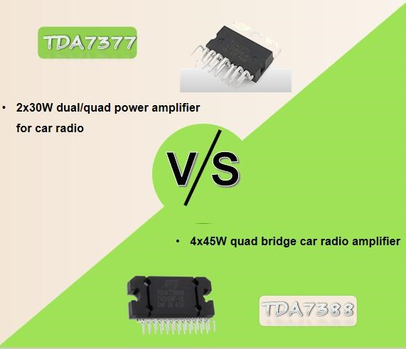 TDA7377 Amplifier vs TDA7388 Amplifier
05 November 202418771
 SHT31 Humidity Sensor: Pinout, Datasheet and Advantages
01 September 202113976
 What is an Encoder?
20 October 20207564
 SAW Filter: Introduction, Features and Applications
30 December 202010761
 What is a Great Choice for Digital Isolators to Build Isolation Barriers?
31 March 20225426
 ChatGPT Will Drive Strong Long-term Growth in the Chip Market in the Future
22 February 20233773
 What is a Resistor Used For?
01 August 20252660
 Vietnam's Semiconductors Market to Grow Rapidly due to Smartphone Adoption
21 September 20232990
 Reed Relays: 10 Key Applications in Modern Electronics
04 July 20253171
 Working Principle and Application of Infrared Sensors
27 October 202517519
Analog Devices Inc.
In Stock: 21
United States
China
Canada
Japan
Russia
Germany
United Kingdom
Singapore
Italy
Hong Kong(China)
Taiwan(China)
France
Korea
Mexico
Netherlands
Malaysia
Austria
Spain
Switzerland
Poland
Thailand
Vietnam
India
United Arab Emirates
Afghanistan
Åland Islands
Albania
Algeria
American Samoa
Andorra
Angola
Anguilla
Antigua & Barbuda
Argentina
Armenia
Aruba
Australia
Azerbaijan
Bahamas
Bahrain
Bangladesh
Barbados
Belarus
Belgium
Belize
Benin
Bermuda
Bhutan
Bolivia
Bonaire, Sint Eustatius and Saba
Bosnia & Herzegovina
Botswana
Brazil
British Indian Ocean Territory
British Virgin Islands
Brunei
Bulgaria
Burkina Faso
Burundi
Cabo Verde
Cambodia
Cameroon
Cayman Islands
Central African Republic
Chad
Chile
Christmas Island
Cocos (Keeling) Islands
Colombia
Comoros
Congo
Congo (DRC)
Cook Islands
Costa Rica
Côte d’Ivoire
Croatia
Cuba
Curaçao
Cyprus
Czechia
Denmark
Djibouti
Dominica
Dominican Republic
Ecuador
Egypt
El Salvador
Equatorial Guinea
Eritrea
Estonia
Eswatini
Ethiopia
Falkland Islands
Faroe Islands
Fiji
Finland
French Guiana
French Polynesia
Gabon
Gambia
Georgia
Ghana
Gibraltar
Greece
Greenland
Grenada
Guadeloupe
Guam
Guatemala
Guernsey
Guinea
Guinea-Bissau
Guyana
Haiti
Honduras
Hungary
Iceland
Indonesia
Iran
Iraq
Ireland
Isle of Man
Israel
Jamaica
Jersey
Jordan
Kazakhstan
Kenya
Kiribati
Kosovo
Kuwait
Kyrgyzstan
Laos
Latvia
Lebanon
Lesotho
Liberia
Libya
Liechtenstein
Lithuania
Luxembourg
Macao(China)
Madagascar
Malawi
Maldives
Mali
Malta
Marshall Islands
Martinique
Mauritania
Mauritius
Mayotte
Micronesia
Moldova
Monaco
Mongolia
Montenegro
Montserrat
Morocco
Mozambique
Myanmar
Namibia
Nauru
Nepal
New Caledonia
New Zealand
Nicaragua
Niger
Nigeria
Niue
Norfolk Island
North Korea
North Macedonia
Northern Mariana Islands
Norway
Oman
Pakistan
Palau
Palestinian Authority
Panama
Papua New Guinea
Paraguay
Peru
Philippines
Pitcairn Islands
Portugal
Puerto Rico
Qatar
Réunion
Romania
Rwanda
Samoa
San Marino
São Tomé & Príncipe
Saudi Arabia
Senegal
Serbia
Seychelles
Sierra Leone
Sint Maarten
Slovakia
Slovenia
Solomon Islands
Somalia
South Africa
South Sudan
Sri Lanka
St Helena, Ascension, Tristan da Cunha
St. Barthélemy
St. Kitts & Nevis
St. Lucia
St. Martin
St. Pierre & Miquelon
St. Vincent & Grenadines
Sudan
Suriname
Svalbard & Jan Mayen
Sweden
Syria
Tajikistan
Tanzania
Timor-Leste
Togo
Tokelau
Tonga
Trinidad & Tobago
Tunisia
Turkey
Turkmenistan
Turks & Caicos Islands
Tuvalu
U.S. Outlying Islands
U.S. Virgin Islands
Uganda
Ukraine
Uruguay
Uzbekistan
Vanuatu
Vatican City
Venezuela
Wallis & Futuna
Yemen
Zambia
Zimbabwe
![AD826AR-REEL7]() AD826AR-REEL7
AD826AR-REEL7Analog Devices Inc.
![AD8062ARM]() AD8062ARM
AD8062ARMAnalog Devices Inc.
![AD8532ARU-REEL]() AD8532ARU-REEL
AD8532ARU-REELAnalog Devices Inc.
![OP113ES]() OP113ES
OP113ESAnalog Devices Inc.
![SSM2142P]() SSM2142P
SSM2142PAnalog Devices, Inc.
![LTC1050CS8]() LTC1050CS8
LTC1050CS8Linear Technology/Analog Devices
![AMP02EPZ]() AMP02EPZ
AMP02EPZAnalog Devices Inc.
![AD822ARZ-REEL7]() AD822ARZ-REEL7
AD822ARZ-REEL7Analog Devices Inc.
![OP2177ARZ-REEL7]() OP2177ARZ-REEL7
OP2177ARZ-REEL7Analog Devices Inc.


