
 Product
 Brand
Brand Articles
 Tools
Tools
AT89C2051-24PU 8-bit Microcontroller: Circuit Diagram, Pinout, and Datasheet [Video&FAQ]

2KB 2K x 8 FLASH 8051 8-Bit Microcontroller 89C Series AT89C2051 20 Pin 24MHz 5V 20-DIP (0.300, 7.62mm)


2KB 2K x 8 FLASH 8051 8-Bit Microcontroller 89C Series AT89C2051 20 Pin 24MHz 5V 20-DIP (0.300, 7.62mm)
The AT89C2051-24PU is a CMOS 8-bit microcontroller in a 20 pin DIP package with low voltage and great performance. This article mainly introduces Circuit Diagram, Pinout, Datasheet and other detailed information about Microchip Technology AT89C2051-24PU.

DIY Electronics Digital Clock AT89C2051 | Construction and Explanation
- AT89C2051-24PU Description
- AT89C2051-24PU Pinout
- AT89C2051-24PU CAD Model
- AT89C2051-24PU Features
- Specifications
- Parts with Similar Specs
- AT89C2051-24PU Functional Block Diagram
- Electronic Digital Clock Using AT89C2051
- AT89C2051-24PU Flash Memory
- AT89C2051-24PU Flash Programming and Verification Waveforms
- AT89C2051-24PU Alternatives
- AT89C2051-24PU Application
- AT89C2051-24PU Package
- AT89C2051-24PU Manufacturer
- Trend Analysis
- Datasheet PDF
AT89C2051-24PU Description
The AT89C2051-24PU is a CMOS 8-bit microcontroller in a 20 pin DIP package with low voltage and great performance. The device is made with high-density nonvolatile memory technology and is compatible with the MCS-51 instruction set, which is widely used in the industry. It combines a versatile 8bit CPU with flash on a monolithic device to deliver a highly adaptable and cost-effective solution for a wide range of applications. On-chip analog comparator, on-chip oscillator, clock circuits, low power idle, and power-down modes are all included in the AT89C2051-24PU. This microcontroller features static logic for operating at low frequencies and two software-selectable power-saving modes. The power-down option saves RAM data but freezes the oscillator, effectively shutting off all chip functions until the next hardware reset.
The following are the standard characteristics of the AT89C2051-24PU: 2K bytes of Flash, 128 bytes of RAM , 15 I/O lines, two 16-bit timer/counters, a five vector two-level interrupt architecture, a full-duplex serial connection, a precision analog comparator, on-chip oscillator, and clock circuits are among the features. The AT89C2051 also features static logic for operation at low frequencies and two software-selectable power-saving modes. The CPU is turned off in Idle Mode, although RAM, timers/counters, serial port, and interrupt system remains operational. The RAM contents are saved in power-down mode, but the oscillator is frozen, rendering all other chip functions useless until the next hardware reset.
AT89C2051-24PU Pinout
The following figure is AT89C2051-24PU Pinout.

Pinout
| Pin Number | Pin Name | Description | |
| 20 | VCC | Supply voltage. | |
| 10 | GND | Ground. | |
| 12-19 | Port 1 | The Port 1 is an 8-bit bi-directional I/O port. Port pins P1.2 to P1.7 provide internal pull-ups. P1.0 and P1.1 requires external pull-ups. P1.0 and P1.1 also serve as the positive input (AIN0) and the negative input (AIN1), respectively, of the on-chip precision analog comparator. The Port 1 out-put buffers can sink 20 mA and can drive LED displays directly. When 1s are written to Port 1 pins, they can be used as inputs. When pins P1.2 to P1.7 are used as inputs and are externally pulled low, they will source current (IIL) because of the internal pull-ups. Port 1 also receives code data during Flash programming and verification. | |
| 2,3,6-9,11 | Port 3 | Port 3 pins P3.0 to P3.5, P3.7 are seven bi-directional I/O pins with internal pull-ups. P3.6 is hard-wired as an input to the output of the on-chip comparator and is not accessible as a general-purpose I/O pin. The Port 3 output buffers can sink 20 mA. When 1s are written to Port 3 pins are pulled high by the internal pull-ups and can be used as inputs. As inputs, Port 3 pins that are externally being pulled low will source current (IIL) because of the pull-ups. Port 3 also serves the functions of various special features of the AT89C2051 as listed below: | |
| Port Pin | Alternate Functions | ||
| P3.0 | RXD (serial input port) | ||
| P3.1 | TXD (serial output port) | ||
| P3.2 | INT0 (external interrupt 0) | ||
| P3.3 | INT1 (external interrupt 1) | ||
| P3.4 | T0 (timer 0 external input) | ||
| P3.5 | T1 (timer 1 external input) | ||
| Port 3 also receives some control signals for Flash programming and verification. | |||
| 1 | RST | Reset input. All I/O pins are reset to 1s as soon as RST goes high. Holding the RST pin high for two machine cycles, while the oscillator is running, reset the device. Each machine cycle takes 12 oscillator or clock cycles. | |
| 5 | XTAL1 | Input to the inverting oscillator amplifier and input to the internal clock operating circuit. | |
| 4 | XTAL2 | Output from the inverting oscillator amplifier. | |
AT89C2051-24PU CAD Model
The followings are AT89C2051-24PU Symbol, Footprint and 3D Model.

Symbol

Footprint

3D Model
AT89C2051-24PU Features
• Compatible with MCS®-51Products
• 2K Bytes of Reprogrammable Flash Memory
– Endurance: 10,000 Write/Erase Cycles
• 2.7V to 6V Operating Range
• Fully Static Operation: 0 Hz to 24 MHz
• Two-level Program Memory Lock
• 128 x 8-bit Internal RAM
• 15 Programmable I/O Lines
• Two 16-bit Timer/Counters
• Six Interrupt Sources
• Programmable Serial UART Channel
• Direct LED Drive Outputs
• On-chip Analog Comparator
• Low-power Idle and Power-down Modes
• Green (Pb/Halide-free) Packaging Option
Specifications
- TypeParameter
- Factory Lead Time10 Weeks
- Mount
In electronic components, the term "Mount" typically refers to the method or process of physically attaching or fixing a component onto a circuit board or other electronic device. This can involve soldering, adhesive bonding, or other techniques to secure the component in place. The mounting process is crucial for ensuring proper electrical connections and mechanical stability within the electronic system. Different components may have specific mounting requirements based on their size, shape, and function, and manufacturers provide guidelines for proper mounting procedures to ensure optimal performance and reliability of the electronic device.
Through Hole - Mounting Type
The "Mounting Type" in electronic components refers to the method used to attach or connect a component to a circuit board or other substrate, such as through-hole, surface-mount, or panel mount.
Through Hole - Package / Case
refers to the protective housing that encases an electronic component, providing mechanical support, electrical connections, and thermal management.
20-DIP (0.300, 7.62mm) - Number of Pins20
- Number of I/Os15
- Operating Temperature
The operating temperature is the range of ambient temperature within which a power supply, or any other electrical equipment, operate in. This ranges from a minimum operating temperature, to a peak or maximum operating temperature, outside which, the power supply may fail.
-40°C~85°C TA - Packaging
Semiconductor package is a carrier / shell used to contain and cover one or more semiconductor components or integrated circuits. The material of the shell can be metal, plastic, glass or ceramic.
Tube - Series
In electronic components, the "Series" refers to a group of products that share similar characteristics, designs, or functionalities, often produced by the same manufacturer. These components within a series typically have common specifications but may vary in terms of voltage, power, or packaging to meet different application needs. The series name helps identify and differentiate between various product lines within a manufacturer's catalog.
89C - Published1995
- JESD-609 Code
The "JESD-609 Code" in electronic components refers to a standardized marking code that indicates the lead-free solder composition and finish of electronic components for compliance with environmental regulations.
e3 - Pbfree Code
The "Pbfree Code" parameter in electronic components refers to the code or marking used to indicate that the component is lead-free. Lead (Pb) is a toxic substance that has been widely used in electronic components for many years, but due to environmental concerns, there has been a shift towards lead-free alternatives. The Pbfree Code helps manufacturers and users easily identify components that do not contain lead, ensuring compliance with regulations and promoting environmentally friendly practices. It is important to pay attention to the Pbfree Code when selecting electronic components to ensure they meet the necessary requirements for lead-free applications.
yes - Part Status
Parts can have many statuses as they progress through the configuration, analysis, review, and approval stages.
Active - Moisture Sensitivity Level (MSL)
Moisture Sensitivity Level (MSL) is a standardized rating that indicates the susceptibility of electronic components, particularly semiconductors, to moisture-induced damage during storage and the soldering process, defining the allowable exposure time to ambient conditions before they require special handling or baking to prevent failures
1 (Unlimited) - Number of Terminations20
- Terminal Position
In electronic components, the term "Terminal Position" refers to the physical location of the connection points on the component where external electrical connections can be made. These connection points, known as terminals, are typically used to attach wires, leads, or other components to the main body of the electronic component. The terminal position is important for ensuring proper connectivity and functionality of the component within a circuit. It is often specified in technical datasheets or component specifications to help designers and engineers understand how to properly integrate the component into their circuit designs.
DUAL - Supply Voltage
Supply voltage refers to the electrical potential difference provided to an electronic component or circuit. It is crucial for the proper operation of devices, as it powers their functions and determines performance characteristics. The supply voltage must be within specified limits to ensure reliability and prevent damage to components. Different electronic devices have specific supply voltage requirements, which can vary widely depending on their design and intended application.
5V - Frequency
In electronic components, the parameter "Frequency" refers to the rate at which a signal oscillates or cycles within a given period of time. It is typically measured in Hertz (Hz) and represents how many times a signal completes a full cycle in one second. Frequency is a crucial aspect in electronic components as it determines the behavior and performance of various devices such as oscillators, filters, and communication systems. Understanding the frequency characteristics of components is essential for designing and analyzing electronic circuits to ensure proper functionality and compatibility with other components in a system.
24MHz - Base Part Number
The "Base Part Number" (BPN) in electronic components serves a similar purpose to the "Base Product Number." It refers to the primary identifier for a component that captures the essential characteristics shared by a group of similar components. The BPN provides a fundamental way to reference a family or series of components without specifying all the variations and specific details.
AT89C2051 - Operating Supply Voltage
The voltage level by which an electrical system is designated and to which certain operating characteristics of the system are related.
5V - Supply Voltage-Max (Vsup)
The parameter "Supply Voltage-Max (Vsup)" in electronic components refers to the maximum voltage that can be safely applied to the component without causing damage. It is an important specification to consider when designing or using electronic circuits to ensure the component operates within its safe operating limits. Exceeding the maximum supply voltage can lead to overheating, component failure, or even permanent damage. It is crucial to adhere to the specified maximum supply voltage to ensure the reliable and safe operation of the electronic component.
6V - Power Supplies
an electronic circuit that converts the voltage of an alternating current (AC) into a direct current (DC) voltage.?
5V - Interface
In electronic components, the term "Interface" refers to the point at which two different systems, devices, or components connect and interact with each other. It can involve physical connections such as ports, connectors, or cables, as well as communication protocols and standards that facilitate the exchange of data or signals between the connected entities. The interface serves as a bridge that enables seamless communication and interoperability between different parts of a system or between different systems altogether. Designing a reliable and efficient interface is crucial in ensuring proper functionality and performance of electronic components and systems.
UART, USART - Memory Size
The memory capacity is the amount of data a device can store at any given time in its memory.
2kB - Oscillator Type
Wien Bridge Oscillator; RC Phase Shift Oscillator; Hartley Oscillator; Voltage Controlled Oscillator; Colpitts Oscillator; Clapp Oscillators; Crystal Oscillators; Armstrong Oscillator.
Internal - RAM Size
RAM size refers to the amount of random access memory (RAM) available in an electronic component, such as a computer or smartphone. RAM is a type of volatile memory that stores data and instructions that are actively being used by the device's processor. The RAM size is typically measured in gigabytes (GB) and determines how much data the device can store and access quickly for processing. A larger RAM size allows for smoother multitasking, faster loading times, and better overall performance of the electronic component. It is an important factor to consider when choosing a device, especially for tasks that require a lot of memory, such as gaming, video editing, or running multiple applications simultaneously.
128 x 8 - Voltage - Supply (Vcc/Vdd)
Voltage - Supply (Vcc/Vdd) is a key parameter in electronic components that specifies the voltage level required for the proper operation of the device. It represents the power supply voltage that needs to be provided to the component for it to function correctly. This parameter is crucial as supplying the component with the correct voltage ensures that it operates within its specified limits and performance characteristics. It is typically expressed in volts (V) and is an essential consideration when designing and using electronic circuits to prevent damage and ensure reliable operation.
4V~6V - uPs/uCs/Peripheral ICs Type
The parameter "uPs/uCs/Peripheral ICs Type" refers to the classification of various integrated circuits used in electronic devices. It encompasses microprocessors (uPs), microcontrollers (uCs), and peripheral integrated circuits that provide additional functionalities. This classification helps in identifying the specific type of chip used for processing tasks, controlling hardware, or interfacing with other components in a system. Understanding this parameter is essential for selecting the appropriate electronic components for a given application.
MICROCONTROLLER - Core Processor
The term "Core Processor" typically refers to the central processing unit (CPU) of a computer or electronic device. It is the primary component responsible for executing instructions, performing calculations, and managing data within the system. The core processor is often considered the brain of the device, as it controls the overall operation and functionality. It is crucial for determining the speed and performance capabilities of the device, as well as its ability to handle various tasks and applications efficiently. In modern devices, core processors can have multiple cores, allowing for parallel processing and improved multitasking capabilities.
8051 - Peripherals
In the context of electronic components, "Peripherals" refer to devices or components that are connected to a main system or device to enhance its functionality or provide additional features. These peripherals can include input devices such as keyboards, mice, and touchscreens, as well as output devices like monitors, printers, and speakers. Other examples of peripherals include external storage devices, network adapters, and cameras. Essentially, peripherals are external devices that expand the capabilities of a main electronic system or device.
LED - Program Memory Type
Program memory typically refers to flash memory when it is used to hold the program (instructions). Program memory may also refer to a hard drive or solid state drive (SSD). Contrast with data memory.
FLASH - Core Size
Core size in electronic components refers to the physical dimensions of the core material used in devices such as inductors and transformers. The core size directly impacts the performance characteristics of the component, including its inductance, saturation current, and frequency response. A larger core size typically allows for higher power handling capabilities and lower core losses, while a smaller core size may result in a more compact design but with limitations on power handling and efficiency. Designers must carefully select the core size based on the specific requirements of the application to achieve optimal performance and efficiency.
8-Bit - Program Memory Size
Program Memory Size refers to the amount of memory available in an electronic component, such as a microcontroller or microprocessor, that is used to store program instructions. This memory is non-volatile, meaning that the data stored in it is retained even when the power is turned off. The program memory size determines the maximum amount of code that can be stored and executed by the electronic component. It is an important parameter to consider when selecting a component for a specific application, as insufficient program memory size may limit the functionality or performance of the device.
2KB 2K x 8 - Connectivity
In electronic components, "Connectivity" refers to the ability of a component to establish and maintain connections with other components or devices within a circuit. It is a crucial parameter that determines how easily signals can be transmitted between different parts of a circuit. Connectivity can be influenced by factors such as the number of input and output ports, the type of connectors used, and the overall design of the component. Components with good connectivity are essential for ensuring reliable and efficient operation of electronic systems.
UART/USART - Bit Size
In electronic components, "Bit Size" refers to the number of bits that can be processed or stored by a particular component. A bit is the smallest unit of data in computing and can have a value of either 0 or 1. The Bit Size parameter is commonly used to describe the capacity or performance of components such as microprocessors, memory modules, and data buses. A larger Bit Size generally indicates a higher processing capability or storage capacity, allowing for more complex operations and larger amounts of data to be handled efficiently. It is an important specification to consider when selecting electronic components for specific applications that require certain levels of performance and data processing capabilities.
8 - Access Time
Access time in electronic components refers to the amount of time it takes for a system to retrieve data from memory or storage once a request has been made. It is typically measured in nanoseconds or microseconds and indicates the speed at which data can be accessed. Lower access time values signify faster performance, allowing for more efficient processing in computing systems. Access time is a critical parameter in determining the overall responsiveness of electronic devices, particularly in applications requiring quick data retrieval.
24 μs - Has ADC
Has ADC refers to the presence of an Analog-to-Digital Converter (ADC) in an electronic component. An ADC is a crucial component in many electronic devices as it converts analog signals, such as voltage or current, into digital data that can be processed by a digital system. Having an ADC allows the electronic component to interface with analog signals and convert them into a format that can be manipulated and analyzed digitally. This parameter is important for applications where analog signals need to be converted into digital form for further processing or control.
NO - DMA Channels
DMA (Direct Memory Access) Channels are a feature found in electronic components such as microcontrollers, microprocessors, and peripheral devices. DMA Channels allow data to be transferred directly between peripherals and memory without involving the CPU, thereby reducing the burden on the CPU and improving overall system performance. Each DMA Channel is typically assigned to a specific peripheral device or memory region, enabling efficient data transfer operations. The number of DMA Channels available in a system determines the concurrent data transfer capabilities and can vary depending on the specific hardware design. Overall, DMA Channels play a crucial role in optimizing data transfer efficiency and system performance in electronic devices.
NO - Data Bus Width
The data bus width in electronic components refers to the number of bits that can be transferred simultaneously between the processor and memory. It determines the amount of data that can be processed and transferred in a single operation. A wider data bus allows for faster data transfer speeds and improved overall performance of the electronic device. Common data bus widths include 8-bit, 16-bit, 32-bit, and 64-bit, with higher numbers indicating a larger capacity for data transfer. The data bus width is an important specification to consider when evaluating the speed and efficiency of a computer system or other electronic device.
8b - PWM Channels
PWM Channels, or Pulse Width Modulation Channels, refer to the number of independent PWM outputs available in an electronic component, such as a microcontroller or a motor driver. PWM is a technique used to generate analog-like signals by varying the duty cycle of a square wave signal. Each PWM channel can control the output of a specific device or component by adjusting the pulse width of the signal. Having multiple PWM channels allows for precise control of multiple devices simultaneously, making it a valuable feature in applications such as motor control, LED dimming, and audio signal generation. The number of PWM channels available in a component determines the flexibility and complexity of the system it can control.
NO - DAC Channels
DAC Channels refer to the number of independent analog output channels available in a digital-to-analog converter (DAC) electronic component. Each channel can convert a digital input signal into an analog output voltage or current. The number of DAC channels determines how many separate analog signals can be generated simultaneously by the DAC. For example, a DAC with two channels can output two different analog signals at the same time, while a DAC with only one channel can only output a single analog signal. The number of DAC channels is an important specification to consider when selecting a DAC for applications requiring multiple analog outputs.
NO - Number of Timers/Counters2
- Address Bus Width
A computer system has an address bus with 8 parallel lines. This means that the address bus width is 8 bits.
8b - Number of UART Channels1
- Height4.963mm
- Length26.92mm
- Width7.112mm
- REACH SVHC
The parameter "REACH SVHC" in electronic components refers to the compliance with the Registration, Evaluation, Authorization, and Restriction of Chemicals (REACH) regulation regarding Substances of Very High Concern (SVHC). SVHCs are substances that may have serious effects on human health or the environment, and their use is regulated under REACH to ensure their safe handling and minimize their impact.Manufacturers of electronic components need to declare if their products contain any SVHCs above a certain threshold concentration and provide information on the safe use of these substances. This information allows customers to make informed decisions about the potential risks associated with using the components and take appropriate measures to mitigate any hazards.Ensuring compliance with REACH SVHC requirements is essential for electronics manufacturers to meet regulatory standards, protect human health and the environment, and maintain transparency in their supply chain. It also demonstrates a commitment to sustainability and responsible manufacturing practices in the electronics industry.
No SVHC - Radiation Hardening
Radiation hardening is the process of making electronic components and circuits resistant to damage or malfunction caused by high levels of ionizing radiation, especially for environments in outer space (especially beyond the low Earth orbit), around nuclear reactors and particle accelerators, or during nuclear accidents or nuclear warfare.
No - RoHS Status
RoHS means “Restriction of Certain Hazardous Substances” in the “Hazardous Substances Directive” in electrical and electronic equipment.
ROHS3 Compliant - Lead Free
Lead Free is a term used to describe electronic components that do not contain lead as part of their composition. Lead is a toxic material that can have harmful effects on human health and the environment, so the electronics industry has been moving towards lead-free components to reduce these risks. Lead-free components are typically made using alternative materials such as silver, copper, and tin. Manufacturers must comply with regulations such as the Restriction of Hazardous Substances (RoHS) directive to ensure that their products are lead-free and environmentally friendly.
Lead Free
Parts with Similar Specs
- ImagePart NumberManufacturerPackage / CaseNumber of PinsData Bus WidthNumber of I/OInterfaceMemory SizeSupply VoltagePeripheralsView Compare
![AT89C2051-24PU]()
AT89C2051-24PU
20-DIP (0.300, 7.62mm)
20
8 b
15
UART, USART
2 kB
5 V
LED
![AT89LP2052-20PU]()
20-DIP (0.300, 7.62mm)
-
-
18
-
-
3 V
LVD, POR, PWM, WDT
![AT89LP214-20PU]()
14-DIP (0.300, 7.62mm)
14
8 b
12
SPI, UART
2 kB
-
Brown-out Detect/Reset, POR, PWM, WDT
![AT89LP213-20PU]()
20-DIP (0.300, 7.62mm)
20
8 b
15
SPI, UART, USART
2 kB
3 V
Brown-out Detect/Reset, POR, PWM, WDT
![MC9RS08KA8CPJ]()
14-DIP (0.300, 7.62mm)
14
8 b
12
SPI, UART, USART
2 kB
2.7 V
Brown-out Detect/Reset, POR, PWM, WDT


AT89C2051-24PU Functional Block Diagram
AT89C2051-24PU Functional Block Diagram is shown as follows.

Functional Block Diagram
Electronic Digital Clock Using AT89C2051
An electronic digital clock, as opposed to an analog clock using a mechanical fitting to indicate time occurrences, is a timepiece that displays the time digitally. Digital clocks are used in practically every aspect of our life and may be found in a variety of locations such as homes, hospitals, schools, and companies. So, in this article, we'll use the Atmel AT89C2051 controller to create a 4-bit Electronic Digital Clock .
The Atmel AT89C2051 is an 8051-based Fully Static 24MHz CMOS controller with 15 I/O Lines, 2 Timers/Counters, 6 Interrupts/2 Priority Levels, Analog Comparator, LED Drive Outputs, UART , Two-level Program Memory Lock, 2K Bytes Flash Memory , 128 Bytes On-chip RAM.

Electronic Digital Clock using AT89C2051
AT89C2051-24PU Flash Memory
The following is AT89C2051-24PU Flash Memory.

Programming the Flash Memory

Verifying the Flash Memory
AT89C2051-24PU Flash Programming and Verification Waveforms
The following figure is AT89C2051-24PU Flash Programming and Verification Waveforms.

Flash Programming and Verification Waveforms
AT89C2051-24PU Alternatives
| Part Number | Description | Manufacturer |
| AT89C2051-24PCMICROCONTROLLERS AND PROCESSORS | Microcontroller, 8-Bit, FLASH, 8051 CPU, 24MHz, CMOS, PDIP20, 0.300 INCH, PLASTIC, MS-001AD, DIP-20 | Atmel Corporation |
| AT89C2051-24PIMICROCONTROLLERS AND PROCESSORS | Microcontroller, 8-Bit, FLASH, 8051 CPU, 24MHz, CMOS, PDIP20, 0.300 INCH, PLASTIC, MS-001AD, DIP-20 | Atmel Corporation |
| AT89C2051-24PUMICROCONTROLLERS AND PROCESSORS | Microcontroller, 8-Bit, FLASH, 8051 CPU, 24MHz, CMOS, PDIP20, 0.300 INCH, GREEN, PLASTIC, MS-001AD, DIP-20 | Atmel Corporation |
AT89C2051-24PU Application
• The Idle Mode stops the CPU while allowing the RAM, timer/counters, serial port and interrupt system to continue functioning.
AT89C2051-24PU Package
The following figure is AT89C2051-24PU Package.

Package
AT89C2051-24PU Manufacturer
Microchip Technology Inc. is a leading provider of microcontroller and analog semiconductors, delivering low-risk product development, reduced overall system cost, and faster time to market to thousands of customers across the world. Microchip, based in Chandler, Arizona, provides excellent technical support as well as consistent delivery and quality.
Trend Analysis
Datasheet PDF
- Datasheets :
- PCN Packaging :
- PCN Assembly/Origin :
- PCN Design/Specification :
- ConflictMineralStatement :
What is the difference between the programming of the microcontroller AT89C51 and AT89C2051?
AT89C2051 can be regarded as a simplified version of AT89C51. If you do not need to expand off-chip RAM, the main differences in ROM are:
1. AT89C51 has 4KB ROM, while AT89C2051 only has 2KB ROM.
2. AT89C51 has 4 8-bit I/O ports, while AT89C2051 has only 2 8-bit I/O ports (P3.6 has no pins).
The internal structure of AT89C2051?
The AT89C2051 is a low voltage, high-performance 8-bit CMOS microprocessor with 2K bytes of Flash Programmable Erasable Read-Only Memory (EEPROM). It is manufactured using ATMEL's high-density non-volatile memory technology and is compatible with the industry-standard MCS-51 instruction set and pin structure. By combining general-purpose CPLI and flash memory on a single chip, ATMEL's AT89C2051 is a powerful microprocessor that provides a highly flexible and low-cost solution for many embedded control applications.
What is the difference between AT89C2051 and AT89S2051?
The way of downloading the program of AT series MCU is different from that of STC.
AT to use parallel port programming
STC can be downloaded directly with MAX232 and a serial port.
AT89S2051 should be used to receive the program of the PC, and then burn into the microcontroller to be programmed, which has been burned into the corresponding program before use.
What is the difference between AT89C2051 and 89C51 MCU?
1. The storage space is half less than 89C51, only 2k.
2. 2051 only retains the p1 and p3 ports, and the p3.7 of 2051 is not on the pins of the chip. It is only used internally. There is no internal pull-up for p1.0 and p1.1. pull.
3. It is not possible to use the c language, because the first instruction of c is a jump, which will waste a lot of space, so the space is not enough, so you can only use assembly.
4. Cannot expand ROM.
What type of package is the AT89C2051-24PU?
20 pin DIP.
What instruction set is the AT89C2051-24PU compatible with?
MCS-51.
What type of CPU does the AT89C2051-24PU combine with flash on a monolithic device?
8bit.
What does the AT89C2051-24PU feature for operating at low frequencies?
Static logic.
What saves RAM data but freezes the oscillator?
The power-down option.
What does the AT89C2051 feature for operation at low frequencies?
Static logic.
When is the CPU turned off?
Idle Mode.
What happens to the RAM contents of the AT89C2051-24PU?
The oscillator is frozen.
 STM32C031C6T6 Datasheet Guide: Complete Beginner's Tutoria
03 July 2025469
 LM124 OP-AMP:Datasheet, Pinout, Advantage
23 September 20212938
 bs250p MOSFET: Datasheet, Equivalent, Pinout, and Specifications
31 March 20225209
 IRF830 Power MOSFET: Pinout, Datasheet, and Test Circuit
14 July 20215534
 RX5500 433.92 MHz Hybrid Receiver:Pinout, Datasheet, and Applications
16 September 20211571
 LM358D Operational Amplifier: Datasheet, Circuits and Pinout
23 July 20218888
 A Comprehensive Guide to LTC6946IUFD-1 Clock/Frequency Synthesizer
06 March 2024276
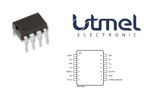 TL3845P Current-Mode PWM Controller:Description;Features and Pinout
25 February 202210633
 What is a Printed Circuit Board?
22 April 20217599
 Methods for measuring the temperature of semiconductor devices
14 November 20222341
 Introduction to Distribution Transformer
24 February 20219263
 The Introduction to PCB Inspection Knowledge and Methods
22 December 20214602
 What Is An Intrinsic Semiconductor?
03 November 202011517
 PMIC - Gate Drivers: A Purpose-Built Integrated Circuit
22 February 20234026
 Introduction to Temperature Sensors
24 October 20259991
 What is Chiplet?
17 November 20214193
Microchip Technology
In Stock: 100
United States
China
Canada
Japan
Russia
Germany
United Kingdom
Singapore
Italy
Hong Kong(China)
Taiwan(China)
France
Korea
Mexico
Netherlands
Malaysia
Austria
Spain
Switzerland
Poland
Thailand
Vietnam
India
United Arab Emirates
Afghanistan
Åland Islands
Albania
Algeria
American Samoa
Andorra
Angola
Anguilla
Antigua & Barbuda
Argentina
Armenia
Aruba
Australia
Azerbaijan
Bahamas
Bahrain
Bangladesh
Barbados
Belarus
Belgium
Belize
Benin
Bermuda
Bhutan
Bolivia
Bonaire, Sint Eustatius and Saba
Bosnia & Herzegovina
Botswana
Brazil
British Indian Ocean Territory
British Virgin Islands
Brunei
Bulgaria
Burkina Faso
Burundi
Cabo Verde
Cambodia
Cameroon
Cayman Islands
Central African Republic
Chad
Chile
Christmas Island
Cocos (Keeling) Islands
Colombia
Comoros
Congo
Congo (DRC)
Cook Islands
Costa Rica
Côte d’Ivoire
Croatia
Cuba
Curaçao
Cyprus
Czechia
Denmark
Djibouti
Dominica
Dominican Republic
Ecuador
Egypt
El Salvador
Equatorial Guinea
Eritrea
Estonia
Eswatini
Ethiopia
Falkland Islands
Faroe Islands
Fiji
Finland
French Guiana
French Polynesia
Gabon
Gambia
Georgia
Ghana
Gibraltar
Greece
Greenland
Grenada
Guadeloupe
Guam
Guatemala
Guernsey
Guinea
Guinea-Bissau
Guyana
Haiti
Honduras
Hungary
Iceland
Indonesia
Iran
Iraq
Ireland
Isle of Man
Israel
Jamaica
Jersey
Jordan
Kazakhstan
Kenya
Kiribati
Kosovo
Kuwait
Kyrgyzstan
Laos
Latvia
Lebanon
Lesotho
Liberia
Libya
Liechtenstein
Lithuania
Luxembourg
Macao(China)
Madagascar
Malawi
Maldives
Mali
Malta
Marshall Islands
Martinique
Mauritania
Mauritius
Mayotte
Micronesia
Moldova
Monaco
Mongolia
Montenegro
Montserrat
Morocco
Mozambique
Myanmar
Namibia
Nauru
Nepal
New Caledonia
New Zealand
Nicaragua
Niger
Nigeria
Niue
Norfolk Island
North Korea
North Macedonia
Northern Mariana Islands
Norway
Oman
Pakistan
Palau
Palestinian Authority
Panama
Papua New Guinea
Paraguay
Peru
Philippines
Pitcairn Islands
Portugal
Puerto Rico
Qatar
Réunion
Romania
Rwanda
Samoa
San Marino
São Tomé & Príncipe
Saudi Arabia
Senegal
Serbia
Seychelles
Sierra Leone
Sint Maarten
Slovakia
Slovenia
Solomon Islands
Somalia
South Africa
South Sudan
Sri Lanka
St Helena, Ascension, Tristan da Cunha
St. Barthélemy
St. Kitts & Nevis
St. Lucia
St. Martin
St. Pierre & Miquelon
St. Vincent & Grenadines
Sudan
Suriname
Svalbard & Jan Mayen
Sweden
Syria
Tajikistan
Tanzania
Timor-Leste
Togo
Tokelau
Tonga
Trinidad & Tobago
Tunisia
Turkey
Turkmenistan
Turks & Caicos Islands
Tuvalu
U.S. Outlying Islands
U.S. Virgin Islands
Uganda
Ukraine
Uruguay
Uzbekistan
Vanuatu
Vatican City
Venezuela
Wallis & Futuna
Yemen
Zambia
Zimbabwe
![ATMEGA8515L-8AU]() ATMEGA8515L-8AU
ATMEGA8515L-8AUMicrochip Technology
![DSPIC30F6014A-30I/PF]() DSPIC30F6014A-30I/PF
DSPIC30F6014A-30I/PFMicrochip Technology
![ATMEGA32A-AU]() ATMEGA32A-AU
ATMEGA32A-AUMicrochip Technology
![ATXMEGA128A1U-AU]() ATXMEGA128A1U-AU
ATXMEGA128A1U-AUMicrochip Technology
![PIC18F46K20-I/PT]() PIC18F46K20-I/PT
PIC18F46K20-I/PTMicrochip Technology
![PIC18F6722-I/PT]() PIC18F6722-I/PT
PIC18F6722-I/PTMicrochip Technology
![PIC16F883-I/SS]() PIC16F883-I/SS
PIC16F883-I/SSMicrochip Technology
![PIC16F877-20I/PT]() PIC16F877-20I/PT
PIC16F877-20I/PTMicrochip Technology
![ATMEGA8535L-8AU]() ATMEGA8535L-8AU
ATMEGA8535L-8AUMicrochip Technology
![PIC18F4685-I/PT]() PIC18F4685-I/PT
PIC18F4685-I/PTMicrochip Technology


