
CC1101 Transceiver: Features, Pinout, and Datasheet

TxRx Only 300MHz~348MHz 387MHz~464MHz 779MHz~928MHz 1.8V~3.6V SPI 600kbps 14.3mA~17.1mA - Receiving 12.3mA~34.2mA - Transmitting 2FSK, 4FSK, ASK, GFSK, MSK, OOK 20-VFQFN Exposed Pad


TxRx Only 300MHz~348MHz 387MHz~464MHz 779MHz~928MHz 1.8V~3.6V SPI 600kbps 14.3mA~17.1mA - Receiving 12.3mA~34.2mA - Transmitting 2FSK, 4FSK, ASK, GFSK, MSK, OOK 20-VFQFN Exposed Pad
The CC1101 is a low-cost sub-1 GHz transceiver for wireless applications that require very little power. The article mainly introduces features, pinout, datasheet and other detailed information about Texas Instruments CC1101.

Cheap DIY Packet Radio based on CC1101 and ATMEGA328 ( ARDUINO ) for 10$
CC1101 Description
The CC1101 is a low-cost sub-1 GHz transceiver for wireless applications that require very little power. The circuit is designed to work in the ISM (Industrial, Scientific, and Medical) and SRD (Short Range Device) frequency bands of 315, 433, 868, and 915 MHz, but it can easily be configured to work in the 300-348 MHz, 387-464 MHz, and 779-928 MHz regions as well. A highly configurable baseband modem is incorporated with the RF transceiver. The modem accepts a variety of modulation types and has a data rate of up to 600 kbps. Packet processing, data buffering, burst broadcasts, clear channel evaluation, link quality indicator, and wake-on-radio are all supported by the CC1101.
An SPI interface can be used to control the CC1101 's major operating settings as well as the 64-byte transmit/receive FIFOs . The CC1101 is typically used in conjunction with a microcontroller and a few other passive components in a typical setup.
In long-range applications, the CC1190 850-950 MHz range extender can be utilized with the CC1101 for better sensitivity and output power.
CC1101 Pinout

Pinout
| Pin Number | Pin Name | Description |
| 1 | SCLK | Serial configuration interface, clock input |
| 2 | SO (GDO1) | Serial configuration interface, data output Optional general output pin when CSn is high |
| 3 | GDO2 | Digital output pin for general use: • Test signals • FIFO status signals • Clear channel indicator • Clock output, down-divided from XOSC • Serial output RX data |
| 4 | DVDD | 1.8 - 3.6 V digital power supply for digital I/O’s and for the digital core voltage regulator |
| 5 | DCOUPL | 1.6 - 2.0 V digital power supply output for decoupling NOTE: This pin is intended for use with the CC1101 only. It can not be used to provide supply voltage to other devices |
| 6 | GDO0 (ATEST) | Digital output pin for general use: • Test signals • FIFO status signals • Clear channel indicator • Clock output, down-divided from XOSC • Serial output RX data • Serial input TX data Also used as analog test I/O for prototype/production testing |
| 7 | CSn | Serial configuration interface, chip select |
| 8 | XOSC_Q1 | Crystal oscillator pin 1, or external clock input |
| 9 | AVDD | 1.8 - 3.6 V analog power supply connection |
| 10 | XOSC_Q2 | Crystal oscillator pin 2 |
| 11 | AVDD | 1.8 - 3.6 V analog power supply connection |
| 12 | RF_P | Positive RF input signal to LNA in receive mode Positive RF output signal from PA in transmit mode |
| 13 | RF_N | Negative RF input signal to LNA in receive mode Negative RF output signal from PA in transmit mode |
| 14 | AVDD | 1.8 - 3.6 V analog power supply connection |
| 15 | AVDD | 1.8 - 3.6 V analog power supply connection |
| 16 | GND | Analog ground connection |
| 17 | RBIAS | External bias resistor for reference current |
| 18 | DGUARD | Power supply connection for digital noise isolation |
| 19 | GND | Ground connection for digital noise isolation |
| 20 | SI | Serial configuration interface, data input |
CC1101 CAD Model

Symbol

Footprint

3D Model
CC1101 Features
(1) RF Performance
• High sensitivity
o -116 dBm at 0.6 kBaud, 433 MHz, 1% packet error rate
o -112 dBm at 1.2 kBaud, 868 MHz, 1% packet error rate
• Low current consumption (14.7 mA in RX, 1.2 kBaud, 868 MHz)
• Programmable output power up to +12 dBm for all supported frequencies
• Excellent receiver selectivity and blocking performance
• Programmable data rate from 0.6 to 600 kbps
• Frequency bands: 300-348 MHz, 387-464 MHz and 779-928 MHz
(2) Analog Features
• 2-FSK, 4-FSK, GFSK, and MSK supported as well as OOK and flexible ASK shaping
• Suitable for frequency hopping systems due to a fast settling frequency synthesizer; 75 μs settling time
• Automatic Frequency Compensation (AFC) can be used to align the frequency synthesizer to the received signal centre frequency
• Integrated analog temperature sensor
(3) Digital Features
• Flexible support for packet-oriented systems; On-chip support for sync word detection, address check, flexible packet length, and automatic CRC handling
• Efficient SPI interface; All registers can be programmed with one “burst” transfer
• Digital RSSI output
• Programmable channel filter bandwidth
• Programmable Carrier Sense (CS) indicator
• Programmable Preamble Quality Indicator (PQI) for improved protection against false sync word detection in random noise
• Support for automatic Clear Channel Assessment (CCA) before transmitting (for listen-before-talk systems)
• Support for per-package Link Quality Indication (LQI)
• Optional automatic whitening and dewhitening of data
(4) Low-Power Features
• 200 nA sleep mode current consumption
• Fast startup time; 240 μs from sleep to RX or TX mode
• Wake-on-radio functionality for automatic low-power RX polling
• Separate 64-byte RX and TX data FIFOs (enables burst mode data transmission)
(5) General
• Few external components; Completely onchip frequency synthesizer, no external filters or switch needed
• Green package: RoHS compliant and no antimony or bromine
• Small size (QLP 4x4 mm package, 20 pins)
• Suited for systems targeting compliance with EN 300 220 (Europe) and FCC CFR Part 15 (US)
• Suited for systems targeting compliance with the Wireless MBUS standard EN 13757-4:2005
• Support for asynchronous and synchronous serial receive/transmit mode for backwards compatibility with existing radio communication protocols
Specifications
- TypeParameter
- Lifecycle Status
Lifecycle Status refers to the current stage of an electronic component in its product life cycle, indicating whether it is active, obsolete, or transitioning between these states. An active status means the component is in production and available for purchase. An obsolete status indicates that the component is no longer being manufactured or supported, and manufacturers typically provide a limited time frame for support. Understanding the lifecycle status is crucial for design engineers to ensure continuity and reliability in their projects.
ACTIVE (Last Updated: 4 days ago) - Factory Lead Time6 Weeks
- Contact Plating
Contact plating (finish) provides corrosion protection for base metals and optimizes the mechanical and electrical properties of the contact interfaces.
Gold - Mount
In electronic components, the term "Mount" typically refers to the method or process of physically attaching or fixing a component onto a circuit board or other electronic device. This can involve soldering, adhesive bonding, or other techniques to secure the component in place. The mounting process is crucial for ensuring proper electrical connections and mechanical stability within the electronic system. Different components may have specific mounting requirements based on their size, shape, and function, and manufacturers provide guidelines for proper mounting procedures to ensure optimal performance and reliability of the electronic device.
Surface Mount - Mounting Type
The "Mounting Type" in electronic components refers to the method used to attach or connect a component to a circuit board or other substrate, such as through-hole, surface-mount, or panel mount.
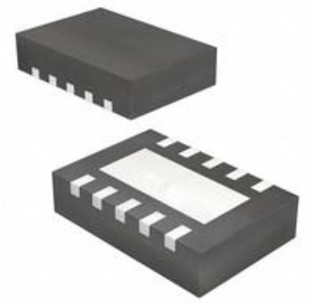
Surface Mount - Package / Case
refers to the protective housing that encases an electronic component, providing mechanical support, electrical connections, and thermal management.
20-VFQFN Exposed Pad - Number of Pins20
- Weight69.994973mg
- Operating Temperature
The operating temperature is the range of ambient temperature within which a power supply, or any other electrical equipment, operate in. This ranges from a minimum operating temperature, to a peak or maximum operating temperature, outside which, the power supply may fail.
-40°C~85°C - Packaging
Semiconductor package is a carrier / shell used to contain and cover one or more semiconductor components or integrated circuits. The material of the shell can be metal, plastic, glass or ceramic.
Tube - JESD-609 Code
The "JESD-609 Code" in electronic components refers to a standardized marking code that indicates the lead-free solder composition and finish of electronic components for compliance with environmental regulations.
e4 - Pbfree Code
The "Pbfree Code" parameter in electronic components refers to the code or marking used to indicate that the component is lead-free. Lead (Pb) is a toxic substance that has been widely used in electronic components for many years, but due to environmental concerns, there has been a shift towards lead-free alternatives. The Pbfree Code helps manufacturers and users easily identify components that do not contain lead, ensuring compliance with regulations and promoting environmentally friendly practices. It is important to pay attention to the Pbfree Code when selecting electronic components to ensure they meet the necessary requirements for lead-free applications.
yes - Part Status
Parts can have many statuses as they progress through the configuration, analysis, review, and approval stages.
Active - Moisture Sensitivity Level (MSL)
Moisture Sensitivity Level (MSL) is a standardized rating that indicates the susceptibility of electronic components, particularly semiconductors, to moisture-induced damage during storage and the soldering process, defining the allowable exposure time to ambient conditions before they require special handling or baking to prevent failures
3 (168 Hours) - Number of Terminations20
- TypeTxRx Only
- Voltage - Supply
Voltage - Supply refers to the range of voltage levels that an electronic component or circuit is designed to operate with. It indicates the minimum and maximum supply voltage that can be applied for the device to function properly. Providing supply voltages outside this range can lead to malfunction, damage, or reduced performance. This parameter is critical for ensuring compatibility between different components in a circuit.
1.8V~3.6V - Terminal Position
In electronic components, the term "Terminal Position" refers to the physical location of the connection points on the component where external electrical connections can be made. These connection points, known as terminals, are typically used to attach wires, leads, or other components to the main body of the electronic component. The terminal position is important for ensuring proper connectivity and functionality of the component within a circuit. It is often specified in technical datasheets or component specifications to help designers and engineers understand how to properly integrate the component into their circuit designs.
QUAD - Peak Reflow Temperature (Cel)
Peak Reflow Temperature (Cel) is a parameter that specifies the maximum temperature at which an electronic component can be exposed during the reflow soldering process. Reflow soldering is a common method used to attach electronic components to a circuit board. The Peak Reflow Temperature is crucial because it ensures that the component is not damaged or degraded during the soldering process. Exceeding the specified Peak Reflow Temperature can lead to issues such as component failure, reduced performance, or even permanent damage to the component. It is important for manufacturers and assemblers to adhere to the recommended Peak Reflow Temperature to ensure the reliability and functionality of the electronic components.
260 - Number of Functions1
- Supply Voltage
Supply voltage refers to the electrical potential difference provided to an electronic component or circuit. It is crucial for the proper operation of devices, as it powers their functions and determines performance characteristics. The supply voltage must be within specified limits to ensure reliability and prevent damage to components. Different electronic devices have specific supply voltage requirements, which can vary widely depending on their design and intended application.
3V - Terminal Pitch
The center distance from one pole to the next.
0.5mm - Depth
In electronic components, "Depth" typically refers to the measurement of the distance from the front to the back of the component. It is an important parameter to consider when designing or selecting components for a project, as it determines how much space the component will occupy within a circuit or device. The depth of a component can impact the overall size and layout of the circuit board or enclosure in which it will be installed. It is usually specified in millimeters or inches and is crucial for ensuring proper fit and functionality within the intended application.
4.15mm - Frequency
In electronic components, the parameter "Frequency" refers to the rate at which a signal oscillates or cycles within a given period of time. It is typically measured in Hertz (Hz) and represents how many times a signal completes a full cycle in one second. Frequency is a crucial aspect in electronic components as it determines the behavior and performance of various devices such as oscillators, filters, and communication systems. Understanding the frequency characteristics of components is essential for designing and analyzing electronic circuits to ensure proper functionality and compatibility with other components in a system.
300MHz~348MHz 387MHz~464MHz 779MHz~928MHz - Base Part Number
The "Base Part Number" (BPN) in electronic components serves a similar purpose to the "Base Product Number." It refers to the primary identifier for a component that captures the essential characteristics shared by a group of similar components. The BPN provides a fundamental way to reference a family or series of components without specifying all the variations and specific details.
CC1101 - Density
In electronic components, "Density" refers to the mass or weight of a material per unit volume. It is a physical property that indicates how tightly packed the atoms or molecules are within the material. The density of a component can affect its performance and characteristics, such as its strength, thermal conductivity, and electrical properties. Understanding the density of electronic components is important for designing and manufacturing processes to ensure optimal performance and reliability.
0 b - Power - Output
Power Output in electronic components refers to the amount of electrical power that a device can deliver to a load. It is typically measured in watts and indicates the effectiveness of the component in converting electrical energy into usable work or signal. Power Output can vary based on the component's design, operating conditions, and intended application, making it a critical factor in the performance of amplifiers, power supplies, and other electronic devices. Understanding the Power Output helps in selecting appropriate components for specific applications to ensure efficiency and reliability.
12dBm - RF Family/Standard
The parameter "RF Family/Standard" in electronic components refers to the specific radio frequency (RF) technology or standard that the component complies with or is designed for. RF technology encompasses a wide range of frequencies used for wireless communication, such as Wi-Fi, Bluetooth, cellular networks, and more. Different RF standards dictate the frequency bands, modulation techniques, data rates, and other specifications for communication systems. Understanding the RF family/standard of a component is crucial for ensuring compatibility and optimal performance in RF applications.
General ISM < 1GHz - Data Rate (Max)
Data Rate (Max) refers to the maximum rate at which data can be transferred or processed within an electronic component or device. It is typically measured in bits per second (bps) or megabits per second (Mbps). This parameter is important for determining the speed and efficiency of data transmission or processing in various electronic applications such as computer systems, networking devices, and memory modules. A higher data rate indicates that the component is capable of handling larger volumes of data at a faster pace, leading to improved performance and responsiveness in electronic systems. It is crucial to consider the Data Rate (Max) specification when selecting electronic components to ensure compatibility and optimal functionality for specific applications.
600kbps - Serial Interfaces
A serial interface is a communication interface between two digital systems that transmits data as a series of voltage pulses down a wire. Essentially, the serial interface encodes the bits of a binary number by their "temporal" location on a wire rather than their "spatial" location within a set of wires.
SPI - Current - Receiving
Current - Receiving refers to the amount of electrical current that an electronic component or device is capable of accepting from a power source or another component in a circuit. It indicates the maximum current that can be safely received without causing damage or malfunction. This parameter is crucial for ensuring compatibility and reliability in electronic designs, as exceeding the rated receiving current can lead to overheating or failure of the component.
14.3mA~17.1mA - Current - Transmitting
Current - Transmitting is a parameter used to describe the maximum amount of electrical current that an electronic component can handle while in the transmitting mode. This parameter is crucial for components such as transistors, diodes, and integrated circuits that are involved in transmitting signals or power within a circuit. Exceeding the specified current transmitting rating can lead to overheating, component failure, or even damage to the entire circuit. Designers and engineers must carefully consider this parameter when selecting components to ensure the reliability and performance of the electronic system.
12.3mA~34.2mA - Number of Receivers1
- Modulation
In electronic components, modulation refers to the process of varying one or more properties of a periodic waveform, known as the carrier signal, in order to encode information. This modulation technique is commonly used in communication systems to transmit data efficiently over long distances. By modulating the carrier signal, information such as audio, video, or data can be embedded onto the signal for transmission and then demodulated at the receiving end to retrieve the original information. There are various types of modulation techniques, including amplitude modulation (AM), frequency modulation (FM), and phase modulation (PM), each with its own advantages and applications in different communication systems.
2FSK, 4FSK, ASK, GFSK, MSK, OOK - Sensitivity (dBm)
Sensitivity (dBm) is a parameter used to measure the minimum input power level required for an electronic component or device to operate effectively. It is typically expressed in decibels relative to one milliwatt (dBm), which is a common unit of power measurement in the field of electronics. A higher sensitivity value indicates that the component can detect weaker input signals, making it more responsive and capable of functioning in low-power conditions. Sensitivity is an important specification for devices like receivers, sensors, and transducers, as it directly impacts their ability to detect and process signals accurately. Manufacturers often provide sensitivity ratings to help users understand the performance capabilities of the component in different operating conditions.
-116 dBm - Height1mm
- Length4mm
- Width4mm
- Thickness
Thickness in electronic components refers to the measurement of how thick a particular material or layer is within the component structure. It can pertain to various aspects, such as the thickness of a substrate, a dielectric layer, or conductive traces. This parameter is crucial as it impacts the electrical, mechanical, and thermal properties of the component, influencing its performance and reliability in electronic circuits.
930μm - REACH SVHC
The parameter "REACH SVHC" in electronic components refers to the compliance with the Registration, Evaluation, Authorization, and Restriction of Chemicals (REACH) regulation regarding Substances of Very High Concern (SVHC). SVHCs are substances that may have serious effects on human health or the environment, and their use is regulated under REACH to ensure their safe handling and minimize their impact.Manufacturers of electronic components need to declare if their products contain any SVHCs above a certain threshold concentration and provide information on the safe use of these substances. This information allows customers to make informed decisions about the potential risks associated with using the components and take appropriate measures to mitigate any hazards.Ensuring compliance with REACH SVHC requirements is essential for electronics manufacturers to meet regulatory standards, protect human health and the environment, and maintain transparency in their supply chain. It also demonstrates a commitment to sustainability and responsible manufacturing practices in the electronics industry.
No SVHC - Radiation Hardening
Radiation hardening is the process of making electronic components and circuits resistant to damage or malfunction caused by high levels of ionizing radiation, especially for environments in outer space (especially beyond the low Earth orbit), around nuclear reactors and particle accelerators, or during nuclear accidents or nuclear warfare.
No - RoHS Status
RoHS means “Restriction of Certain Hazardous Substances” in the “Hazardous Substances Directive” in electrical and electronic equipment.
ROHS3 Compliant - Lead Free
Lead Free is a term used to describe electronic components that do not contain lead as part of their composition. Lead is a toxic material that can have harmful effects on human health and the environment, so the electronics industry has been moving towards lead-free components to reduce these risks. Lead-free components are typically made using alternative materials such as silver, copper, and tin. Manufacturers must comply with regulations such as the Restriction of Hazardous Substances (RoHS) directive to ensure that their products are lead-free and environmentally friendly.
Lead Free
Parts with Similar Specs
- ImagePart NumberManufacturerPackage / CaseNumber of PinsFrequencyCurrent - ReceivingCurrent - TransmittingSensitivity (dBm)Supply VoltageTerminal PitchView Compare
![CC1101RGP]()
CC1101RGP
20-VFQFN Exposed Pad
20
300MHz ~ 348MHz, 387MHz ~ 464MHz, 779MHz ~ 928MHz
14.3mA ~ 17.1mA
12.3mA ~ 34.2mA
-116 dBm
3 V
0.5 mm
![CC115LRGPR]()
20-VFQFN Exposed Pad
20
300MHz ~ 348MHz, 400MHz ~ 464MHz, 800MHz ~ 928MHz
13.9mA ~ 15.9mA
12.3mA ~ 31.1mA
-112 dBm
3 V
0.5 mm
![CC110LRGPR]()
20-VFQFN Exposed Pad
20
300MHz ~ 348MHz, 400MHz ~ 464MHz, 800MHz ~ 928MHz
13.9mA ~ 15.9mA
12.3mA ~ 31.1mA
-111 dBm
3 V
0.5 mm
![CC1100RTKR]()
20-VFQFN Exposed Pad
20
315MHz, 433MHz, 868MHz, 915MHz
-
-
-
3 V
0.5 mm
![CC1100RTK]()
20-VFQFN Exposed Pad
20
300MHz ~ 348MHz, 387MHz ~ 464MHz, 779MHz ~ 928MHz
14.3mA ~ 17.1mA
12.3mA ~ 34.2mA
-116 dBm
3 V
0.5 mm


CC1101 Functional Block Diagram

Functional Block Diagram
The image above shows a simplified block diagram of the CC1101. The CC1101 is equipped with a low-IF receiver. The low-noise amplifier (LNA) amplifies the received RF signal and converts it to the intermediate frequency in quadrature (I and Q) (IF). The ADCs digitize the I/Q signals at the IF. Digitally executed functions include automatic gain control (AGC), precise channel filtering, demodulation, and bit/packet synchronization.
The transmitter section of the CC1101 uses direct RF frequency synthesis.
In receive mode, the frequency synthesizer has an on-chip LC VCO and a 90-degree phase shifter for creating the I and Q LO signals for the down-conversion mixers. To XOSC Q1 and XOSC Q2, a crystal must be connected. The crystal oscillator generates the synthesizer's reference frequency as well as clocks for the ADC and digital section.
For configuration and data buffer access, a 4-wire SPI serial interface is employed. Channel setting, packet handling, and data buffering are all supported by the digital baseband.
CC1101 Typical Application

Typical Application and Evaluation Circuit 315/433 MHz (excluding supply decoupling capacitors)

Typical Application and Evaluation Circuit 868/915 MHz (excluding supply decoupling capacitors)
CC1101 Alternatives
| Part Number | Description | Manufacturer |
| CC1100ERGPTTELECOMMUNICATION CIRCUITS | Low-power Sub-1GHz wireless transceiver for China and Japan frequency bands 20-QFN -40 to 85 | Texas Instruments |
| MD59-0049RTRTELECOMMUNICATION CIRCUITS | RF and Baseband Circuit, PQCC20, 4 MM, PLASTIC, MLF-20 | MACOM |
| CC1101RTKRG3TELECOMMUNICATION CIRCUITS | IC TELECOM, CELLULAR, RF AND BASEBAND CIRCUIT, PQCC20, 4 X 4 MM, GREEN, PLASTIC, QLP-20, Cellular Telephone Circuit | Texas Instruments |
| CC1101RTKTELECOMMUNICATION CIRCUITS | TELECOM, CELLULAR, RF AND BASEBAND CIRCUIT, PQCC20, 4 X 4 MM, GREEN, PLASTIC, QLP-20 | Texas Instruments |
| CC1101RTKG3TELECOMMUNICATION CIRCUITS | TELECOM, CELLULAR, RF AND BASEBAND CIRCUIT, PQCC20, 4 X 4 MM, GREEN, PLASTIC, QLP-20 | Texas Instruments |
CC1101 Applications
• Ultra low-power wireless applications operating in the 315/433/868/915 MHz ISM/SRD bands
• Wireless alarm and security systems
• Industrial monitoring and control
• Wireless sensor networks
• AMR – Automatic Meter Reading
• Home and building automation
• Wireless MBUS
CC1101 Package

Package
CC1101 Manufacturer
Texas Instruments (TI), a multinational semiconductor business with operations in 35 countries, is first and foremost a reflection of its employees. We are problem-solvers cooperating to transform the world via technology, from the TIer who introduced the first functional integrated circuit in 1958 to the more than 30,000 TIers throughout the world today who develop, build, and distribute analog and embedded processor chips.
Trend Analysis
Datasheet PDF
- PCN Design/Specification :
- Datasheets :
- PCN Assembly/Origin :
1.Which is easier to configure and use, CC1101 or SI4432?
The number of configuration registers required by CC1101 is far less than SI4432, and CC1101 can use the SmartRF Studio officially provided by TI for auxiliary configuration. So CC1101 is easier to configure and use than SI4432.
2.How to increase the anti-interference ability of CC1101?
433MHz is originally a straight line propagation, the anti-interference level is determined by the chip itself, and only other methods can be used to ensure the success rate of communication. For example: add a shielding cover to the hardware to isolate the power supply. The software protocol increases the preamble length, the synchronization word is allocated with 0x5A, 0xA5, or something, add the hardware address, software number, and add a CRC16. The interfered data packet is lost and retransmitted. The frequency offset bandwidth is narrowed a bit, the sensitivity is reduced, and then the communication rate is reduced, and the transmission power is increased.
3.What is the difference between CC1101 chip and CC1101-Q1?
The performance is the same, but the levels are different. CC1101 is an ordinary grade, and CC1101-Q is an automotive-grade, with a relatively wide operating temperature range.
4.The information of Arduino Uno chip (ATMEGA328P) and CC1101 based breadboard, what is an Arduino used for?
Arduino is an open-source electronics platform that uses simple hardware and software to make it easy to use. Arduino boards can take inputs - such as light from a sensor, a finger on a button, or a Twitter message - and convert them to outputs - such as turning on an LED, triggering a motor, or publishing anything online.
 TPS62175DQCR:Step-Down, Converter, Pinout
01 March 20221201
![1SMB5923BT3G Zener Voltage Regulator: Pinout, Equivalent and Datasheet [Video]](https://res.utmel.com/Images/Article/46c3c894-7e2a-42f2-83a6-e6186e06548a.png) 1SMB5923BT3G Zener Voltage Regulator: Pinout, Equivalent and Datasheet [Video]
1SMB5923BT3G Zener Voltage Regulator: Pinout, Equivalent and Datasheet [Video]29 April 20221030
 UC3843 PWM Controller: Pinout, Datasheet and Uses
16 August 202146287
 AD823 Op-Amp Troubleshooting Guide: Common Failures and Repair Solutions
04 July 2025573
 74HC165 Shift Registers: Features, Speicifications and Applications
25 May 20212035
![Difference between ADS1115 and ADS1015 ADS1115 VS ADS1015[Video]](https://res.utmel.com/Images/Article/2a7a0080-ee2c-41dd-8576-d6c565fbe343.png) Difference between ADS1115 and ADS1015 ADS1115 VS ADS1015[Video]
Difference between ADS1115 and ADS1015 ADS1115 VS ADS1015[Video]22 April 20256059
 CR2354 Lithium Battery: CR2354 Battery Equivalent, 3V Coin CR2354, and Replacement
18 November 202118097
![H1102NL How to use H1102NL?[FAQ&Video]](https://res.utmel.com/Images/Article/332ed242-9496-43e7-972e-bd59447bd7b2.png) H1102NL How to use H1102NL?[FAQ&Video]
H1102NL How to use H1102NL?[FAQ&Video]09 May 20224683
 What is Time Delay Relay?
18 December 202512051
 Optimizing Energy Exchange with Vehicle-to-Grid Technology
25 April 20232858
 What are Laser Diodes?
20 October 202514553
 In-depth Analysis of the Global Semiconductor Supply Chain
20 January 202212418
 Semiconductor Devices: Impact on IoT and Modern Communication (Part-1)
22 July 20242257
 This New Material Promises to Be the Best Semiconductor
25 July 20221019
 Chinese Chip Equipment Makers Thrive Amid US Restrictions
24 October 2023623
 Six Sensor Principles
18 December 2021969
Texas Instruments
In Stock: 130
United States
China
Canada
Japan
Russia
Germany
United Kingdom
Singapore
Italy
Hong Kong(China)
Taiwan(China)
France
Korea
Mexico
Netherlands
Malaysia
Austria
Spain
Switzerland
Poland
Thailand
Vietnam
India
United Arab Emirates
Afghanistan
Åland Islands
Albania
Algeria
American Samoa
Andorra
Angola
Anguilla
Antigua & Barbuda
Argentina
Armenia
Aruba
Australia
Azerbaijan
Bahamas
Bahrain
Bangladesh
Barbados
Belarus
Belgium
Belize
Benin
Bermuda
Bhutan
Bolivia
Bonaire, Sint Eustatius and Saba
Bosnia & Herzegovina
Botswana
Brazil
British Indian Ocean Territory
British Virgin Islands
Brunei
Bulgaria
Burkina Faso
Burundi
Cabo Verde
Cambodia
Cameroon
Cayman Islands
Central African Republic
Chad
Chile
Christmas Island
Cocos (Keeling) Islands
Colombia
Comoros
Congo
Congo (DRC)
Cook Islands
Costa Rica
Côte d’Ivoire
Croatia
Cuba
Curaçao
Cyprus
Czechia
Denmark
Djibouti
Dominica
Dominican Republic
Ecuador
Egypt
El Salvador
Equatorial Guinea
Eritrea
Estonia
Eswatini
Ethiopia
Falkland Islands
Faroe Islands
Fiji
Finland
French Guiana
French Polynesia
Gabon
Gambia
Georgia
Ghana
Gibraltar
Greece
Greenland
Grenada
Guadeloupe
Guam
Guatemala
Guernsey
Guinea
Guinea-Bissau
Guyana
Haiti
Honduras
Hungary
Iceland
Indonesia
Iran
Iraq
Ireland
Isle of Man
Israel
Jamaica
Jersey
Jordan
Kazakhstan
Kenya
Kiribati
Kosovo
Kuwait
Kyrgyzstan
Laos
Latvia
Lebanon
Lesotho
Liberia
Libya
Liechtenstein
Lithuania
Luxembourg
Macao(China)
Madagascar
Malawi
Maldives
Mali
Malta
Marshall Islands
Martinique
Mauritania
Mauritius
Mayotte
Micronesia
Moldova
Monaco
Mongolia
Montenegro
Montserrat
Morocco
Mozambique
Myanmar
Namibia
Nauru
Nepal
New Caledonia
New Zealand
Nicaragua
Niger
Nigeria
Niue
Norfolk Island
North Korea
North Macedonia
Northern Mariana Islands
Norway
Oman
Pakistan
Palau
Palestinian Authority
Panama
Papua New Guinea
Paraguay
Peru
Philippines
Pitcairn Islands
Portugal
Puerto Rico
Qatar
Réunion
Romania
Rwanda
Samoa
San Marino
São Tomé & Príncipe
Saudi Arabia
Senegal
Serbia
Seychelles
Sierra Leone
Sint Maarten
Slovakia
Slovenia
Solomon Islands
Somalia
South Africa
South Sudan
Sri Lanka
St Helena, Ascension, Tristan da Cunha
St. Barthélemy
St. Kitts & Nevis
St. Lucia
St. Martin
St. Pierre & Miquelon
St. Vincent & Grenadines
Sudan
Suriname
Svalbard & Jan Mayen
Sweden
Syria
Tajikistan
Tanzania
Timor-Leste
Togo
Tokelau
Tonga
Trinidad & Tobago
Tunisia
Turkey
Turkmenistan
Turks & Caicos Islands
Tuvalu
U.S. Outlying Islands
U.S. Virgin Islands
Uganda
Ukraine
Uruguay
Uzbekistan
Vanuatu
Vatican City
Venezuela
Wallis & Futuna
Yemen
Zambia
Zimbabwe
![CC1310F128RGZT]() CC1310F128RGZT
CC1310F128RGZTTexas Instruments
![CC2650F128RSMT]() CC2650F128RSMT
CC2650F128RSMTTexas Instruments
![CC1101RGPR]() CC1101RGPR
CC1101RGPRTexas Instruments
![CC1125RHBR]() CC1125RHBR
CC1125RHBRTexas Instruments
![CC1110F32RHHR]() CC1110F32RHHR
CC1110F32RHHRTexas Instruments
![CC430F5137IRGZR]() CC430F5137IRGZR
CC430F5137IRGZRTexas Instruments
![CC2540F256RHAR]() CC2540F256RHAR
CC2540F256RHARTexas Instruments
![CC1310F128RHBR]() CC1310F128RHBR
CC1310F128RHBRTexas Instruments
![CC2640F128RHBR]() CC2640F128RHBR
CC2640F128RHBRTexas Instruments
![CC2564BRVMT]() CC2564BRVMT
CC2564BRVMTTexas Instruments


