
 Product
 Brand
Brand Articles
 Tools
Tools
MLX90614 Infra Red Thermometer: Pinout, Datasheet and Applications
Tube Digital, Infrared (IR) 2.6V~3.6V Through Hole -40°C~85°C PWM, SMBus ±0.5°C (±4°C) 16 b 1 (Unlimited)
Unit Price: $24.240126
Ext Price: $24.24


Tube Digital, Infrared (IR) 2.6V~3.6V Through Hole -40°C~85°C PWM, SMBus ±0.5°C (±4°C) 16 b 1 (Unlimited)
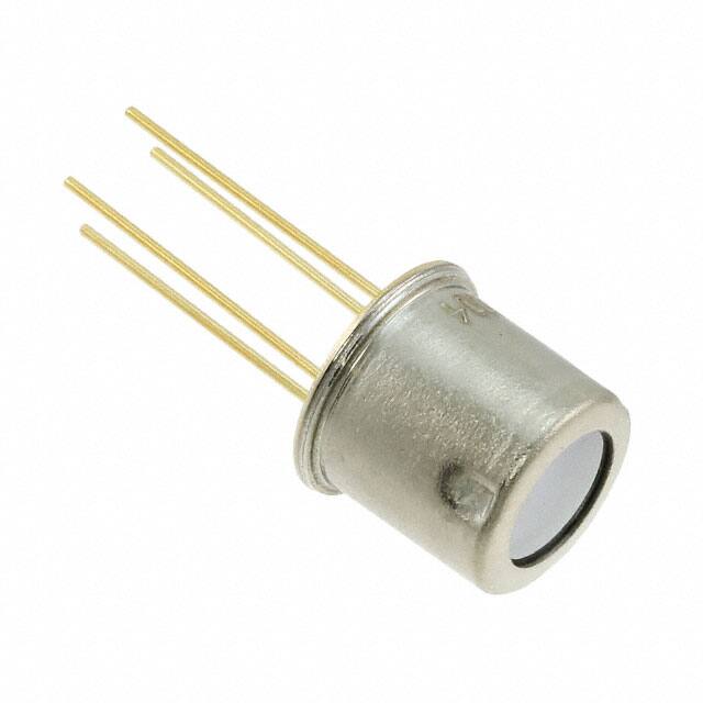
The MLX90614 is an Infra Red thermometer for noncontact temperature measurements. This article mainly covers pinout, datasheet, schematic, features and other details about MLX90614.

Non-contact temperature sensor mlx90614 with arduino tutorial
- MLX90614 Pinout
- MLX90614 Description
- MLX90614 CAD Model
- MLX90614 Block Diagram
- Specifications
- MLX90614 Benefits and Features
- MLX90614 Functional Diagram
- MLX90614 Alternative
- MLX90614 Applications
- MLX90614 Application Circuit
- Where to use MLX90614
- How to use MLX90614
- MLX90614 Dimension Outline
- MLX90614 Manufacturer
- Datasheet PDF
MLX90614 Pinout


MLX90614 Description
The MLX90614 is an Infra Red thermometer for noncontact temperature measurements. Both the IR sensitive thermopile detector chip and the signal conditioning ASSP are integrated in the same TO-39 can.
Thanks to its low noise amplifier, 17-bit ADC and powerful DSP unit, a high accuracy and resolution of the thermometer is achieved.
MLX90614 CAD Model
Symbol

Footprint

3D Model

MLX90614 Block Diagram

Specifications
- TypeParameter
- Factory Lead Time20 Weeks
- Mounting Type
The "Mounting Type" in electronic components refers to the method used to attach or connect a component to a circuit board or other substrate, such as through-hole, surface-mount, or panel mount.
Through Hole - Package / Case
refers to the protective housing that encases an electronic component, providing mechanical support, electrical connections, and thermal management.
TO-205AD, TO-39-4 Modified Metal Can - Surface Mount
having leads that are designed to be soldered on the side of a circuit board that the body of the component is mounted on.
NO - Test Conditions0°C ~ 60°C (120°C ~ 380°C)
- Operating Temperature
The operating temperature is the range of ambient temperature within which a power supply, or any other electrical equipment, operate in. This ranges from a minimum operating temperature, to a peak or maximum operating temperature, outside which, the power supply may fail.
-40°C~85°C - Packaging
Semiconductor package is a carrier / shell used to contain and cover one or more semiconductor components or integrated circuits. The material of the shell can be metal, plastic, glass or ceramic.
Tube - Published2012
- Part Status
Parts can have many statuses as they progress through the configuration, analysis, review, and approval stages.
Active - Moisture Sensitivity Level (MSL)
Moisture Sensitivity Level (MSL) is a standardized rating that indicates the susceptibility of electronic components, particularly semiconductors, to moisture-induced damage during storage and the soldering process, defining the allowable exposure time to ambient conditions before they require special handling or baking to prevent failures
1 (Unlimited) - Number of Terminations4
- HTS Code
HTS (Harmonized Tariff Schedule) codes are product classification codes between 8-1 digits. The first six digits are an HS code, and the countries of import assign the subsequent digits to provide additional classification. U.S. HTS codes are 1 digits and are administered by the U.S. International Trade Commission.
8542.39.00.01 - Voltage - Supply
Voltage - Supply refers to the range of voltage levels that an electronic component or circuit is designed to operate with. It indicates the minimum and maximum supply voltage that can be applied for the device to function properly. Providing supply voltages outside this range can lead to malfunction, damage, or reduced performance. This parameter is critical for ensuring compatibility between different components in a circuit.
2.6V~3.6V - Terminal Position
In electronic components, the term "Terminal Position" refers to the physical location of the connection points on the component where external electrical connections can be made. These connection points, known as terminals, are typically used to attach wires, leads, or other components to the main body of the electronic component. The terminal position is important for ensuring proper connectivity and functionality of the component within a circuit. It is often specified in technical datasheets or component specifications to help designers and engineers understand how to properly integrate the component into their circuit designs.
BOTTOM - Peak Reflow Temperature (Cel)
Peak Reflow Temperature (Cel) is a parameter that specifies the maximum temperature at which an electronic component can be exposed during the reflow soldering process. Reflow soldering is a common method used to attach electronic components to a circuit board. The Peak Reflow Temperature is crucial because it ensures that the component is not damaged or degraded during the soldering process. Exceeding the specified Peak Reflow Temperature can lead to issues such as component failure, reduced performance, or even permanent damage to the component. It is important for manufacturers and assemblers to adhere to the recommended Peak Reflow Temperature to ensure the reliability and functionality of the electronic components.
NOT SPECIFIED - Number of Functions1
- Supply Voltage
Supply voltage refers to the electrical potential difference provided to an electronic component or circuit. It is crucial for the proper operation of devices, as it powers their functions and determines performance characteristics. The supply voltage must be within specified limits to ensure reliability and prevent damage to components. Different electronic devices have specific supply voltage requirements, which can vary widely depending on their design and intended application.
3V - Time@Peak Reflow Temperature-Max (s)
Time@Peak Reflow Temperature-Max (s) refers to the maximum duration that an electronic component can be exposed to the peak reflow temperature during the soldering process, which is crucial for ensuring reliable solder joint formation without damaging the component.
NOT SPECIFIED - JESD-30 Code
JESD-30 Code refers to a standardized descriptive designation system established by JEDEC for semiconductor-device packages. This system provides a systematic method for generating designators that convey essential information about the package's physical characteristics, such as size and shape, which aids in component identification and selection. By using JESD-30 codes, manufacturers and engineers can ensure consistency and clarity in the specification of semiconductor packages across various applications and industries.
O-MBCY-T4 - Output Type
The "Output Type" parameter in electronic components refers to the type of signal or data that is produced by the component as an output. This parameter specifies the nature of the output signal, such as analog or digital, and can also include details about the voltage levels, current levels, frequency, and other characteristics of the output signal. Understanding the output type of a component is crucial for ensuring compatibility with other components in a circuit or system, as well as for determining how the output signal can be utilized or processed further. In summary, the output type parameter provides essential information about the nature of the signal that is generated by the electronic component as its output.
PWM, SMBus - Supply Voltage-Max (Vsup)
The parameter "Supply Voltage-Max (Vsup)" in electronic components refers to the maximum voltage that can be safely applied to the component without causing damage. It is an important specification to consider when designing or using electronic circuits to ensure the component operates within its safe operating limits. Exceeding the maximum supply voltage can lead to overheating, component failure, or even permanent damage. It is crucial to adhere to the specified maximum supply voltage to ensure the reliable and safe operation of the electronic component.
3.6V - Supply Voltage-Min (Vsup)
The parameter "Supply Voltage-Min (Vsup)" in electronic components refers to the minimum voltage level required for the component to operate within its specified performance range. This parameter indicates the lowest voltage that can be safely applied to the component without risking damage or malfunction. It is crucial to ensure that the supply voltage provided to the component meets or exceeds this minimum value to ensure proper functionality and reliability. Failure to adhere to the specified minimum supply voltage may result in erratic behavior, reduced performance, or even permanent damage to the component.
2.6V - Analog IC - Other Type
Analog IC - Other Type is a parameter used to categorize electronic components that are integrated circuits (ICs) designed for analog signal processing but do not fall into more specific subcategories such as amplifiers, comparators, or voltage regulators. These ICs may include specialized analog functions such as analog-to-digital converters (ADCs), digital-to-analog converters (DACs), voltage references, or signal conditioning circuits. They are typically used in various applications where precise analog signal processing is required, such as in audio equipment, instrumentation, communication systems, and industrial control systems. Manufacturers provide detailed specifications for these components to help engineers select the most suitable IC for their specific design requirements.
ANALOG CIRCUIT - Resolution
Resolution in electronic components refers to the smallest increment of measurement or change that can be detected or represented by the component. It is a crucial specification in devices such as sensors, displays, and converters, as it determines the level of detail or accuracy that can be achieved. For example, in a digital camera, resolution refers to the number of pixels that make up an image, with higher resolution indicating a greater level of detail. In analog-to-digital converters, resolution is the number of discrete values that can be represented in the digital output, determining the precision of the conversion process. Overall, resolution plays a significant role in determining the performance and capabilities of electronic components in various applications.
16 b - Sensor Type
In electronic components, the parameter "Sensor Type" refers to the specific type of sensor technology used in a particular component to detect and measure physical phenomena such as light, temperature, pressure, motion, or proximity. Different sensor types utilize various principles and mechanisms to convert the detected input into an electrical signal that can be processed by the electronic component. Common sensor types include photodiodes, thermistors, accelerometers, and proximity sensors, each designed for specific applications and environments. Understanding the sensor type is crucial for selecting the right component for a given task and ensuring accurate and reliable sensing capabilities in electronic systems.
Digital, Infrared (IR) - Sensing Method
The sensing method in electronic components refers to the technique or mechanism used to detect and measure physical phenomena such as temperature, pressure, light, or motion. This includes a variety of technologies such as resistive, capacitive, inductive, and optical sensing methods. The choice of sensing method affects the accuracy, response time, and application suitability of the electronic component. It plays a crucial role in determining how effectively a device can interact with and interpret its environment.
Infrared (IR) - Accuracy - Highest (Lowest)
In electronic components, "Accuracy - Highest (Lowest)" refers to the range within which the actual value of a parameter can deviate from the ideal or specified value. The term "Highest" indicates the upper limit of this range, while "Lowest" indicates the lower limit. For example, if a component has an accuracy of ±5%, the highest accuracy would mean that the actual value could be within 5% above the specified value, while the lowest accuracy would mean it could be within 5% below the specified value. This parameter is crucial for ensuring the reliability and performance of electronic devices by determining how closely the component's output matches the desired value.
±0.5°C (±4°C) - Sensing Temperature - Local
Sensing Temperature - Local refers to the capability of an electronic component to measure the temperature in its immediate environment or vicinity. This parameter is crucial for applications that require monitoring of temperature for performance, safety, or stability purposes. It often involves temperature sensors integrated within components like microcontrollers, power regulators, or other integrated circuits. The local sensing allows for accurate temperature readings that help in adjusting operational conditions, ensuring optimal performance, and preventing thermal-related failures.
-40°C~85°C - Sensing Temperature - Remote
Sensing Temperature - Remote refers to the capability of electronic components to measure temperature at a location that is distant from the main control unit or sensor. This parameter typically involves the use of external temperature probes or sensors that are connected to a monitoring device, allowing for accurate temperature readings in environments that are difficult to access. Remote sensing is crucial in applications like HVAC systems, industrial processes, and environmental monitoring, where precise temperature data is needed from various locations.
-70°C~380°C IR - Features
In the context of electronic components, the term "Features" typically refers to the specific characteristics or functionalities that a particular component offers. These features can vary depending on the type of component and its intended use. For example, a microcontroller may have features such as built-in memory, analog-to-digital converters, and communication interfaces like UART or SPI.When evaluating electronic components, understanding their features is crucial in determining whether they meet the requirements of a particular project or application. Engineers and designers often look at features such as operating voltage, speed, power consumption, and communication protocols to ensure compatibility and optimal performance.In summary, the "Features" parameter in electronic components describes the unique attributes and capabilities that differentiate one component from another, helping users make informed decisions when selecting components for their electronic designs.
Sleep Mode - RoHS Status
RoHS means “Restriction of Certain Hazardous Substances” in the “Hazardous Substances Directive” in electrical and electronic equipment.
RoHS Compliant - Lead Free
Lead Free is a term used to describe electronic components that do not contain lead as part of their composition. Lead is a toxic material that can have harmful effects on human health and the environment, so the electronics industry has been moving towards lead-free components to reduce these risks. Lead-free components are typically made using alternative materials such as silver, copper, and tin. Manufacturers must comply with regulations such as the Restriction of Hazardous Substances (RoHS) directive to ensure that their products are lead-free and environmentally friendly.
Lead Free
MLX90614 Benefits and Features
Small size, low cost
Easy to integrate
Factory calibrated in wide temperature range:
-40°C…+125˚C for sensor temperature and
-70°C…+380˚C for object temperature.
High accuracy of 0.5°C in a wide temperature range (0°C…+50°C for both Ta and To)
High (medical) accuracy calibration
Measurement resolution of 0.02°C
Single and dual zone versions
SMBus compatible digital interface
Customizable PWM output for continuous reading
Available in 3V and 5V versions
Simple adaptation for 8V…16V applications
Sleep mode for reduced power consumption
Different package options for applications and measurements versatility
Automotive grade
MLX90614 Functional Diagram

MLX90614 Alternative
MLX90615, ZTP115, TPIS 1S
MLX90614 Applications
High precision non-contact temperature measurements
Thermal Comfort sensor for Mobile Air Conditioning control system
Temperature sensing element for residential, commercial and industrial building air conditioning
Windshield defogging
Automotive blind angle detection
Industrial temperature control of moving parts
Temperature control in printers and copiers
Home appliances with temperature control
Healthcare
Livestock monitoring
Movement detection
Multiple zone temperature control – up to 127 sensors can be read via common 2 wires
Thermal relay / alert
Body temperature measurement
MLX90614 Application Circuit
Use of the MLX90614 thermometer in SMBus configuration

Where to use MLX90614
The key feature of MLX90614 is that it is a contactless IR temperature sensor with high accuracy. Therefore, it can be used in industries to measure the temperature of moving objects like a rotating motor shaft. With its high accuracy and precision, it is also used in a wide range of commercial, health care, and household applications like room temperature monitoring, body temperature measurement, etc.
How to use MLX90614
The MLX90614 Temperature sensor is manufactured by a company called Melexis. The sensor is factory calibrated and hence it acts like a plug and play sensor module for speeding up development processes.
MLX90614 Dimension Outline
The MLX90614 is available in the standard TO-39 package making it easy to mount on a breadboard. The dimensions of MLX90614 is shown below.

MLX90614 Manufacturer
Combining a passion for technology with truly inspired engineering, Melexis designs, develops and delivers innovative micro-electronic solutions that enable designers to turn ideas into applications that support the best imaginable future. The company’s advanced mixed-signal semiconductor sensor and actuator components address the challenges of integrating sensing, driving and communication into next-generation products and systems that improve safety, raise efficiency, support sustainability and enhance comfort. Melexis is headquartered in Belgium and employs over 1,500 people in 19 locations worldwide. The company is publicly traded on Euronext Brussels (MELE).
Datasheet PDF
- Datasheets :
After I put the MLX90614 in the dashboard I start getting errors larger than specified in spite that the module was working properly before that. Why?
Any object present in the FOV of the module provides IR signal. It is actually possible to introduce error in the measurements if the module is attached to the dashboard with an opening that enters the FOV. In that case portion of the dashboard opening will introduce IR signal in conjunction with constraining the effective FOV and thus compromising specified accuracy. Relevant opening that takes in account the FOV is a must for accurate measurements. Note that the basic FOV specification takes 50% of IR signal as threshold (in order to define the area, where the measurements are relevant), while the entire FOV at lower level is capable of introducing lateral IR signal under many conditions.
How do I program my MLX90614?
1.Connect GND to common power/data ground.
2.Connect PWR to the power supply, for the 3V sensor this is about 3.3V. For the 5V version, use about 5VDC.
3.Connect the SDA pin to the I2C data SDA pin on your Arduino. ...
4.Connect the SCL pin to the I2C clock SCL pin on your Arduino.
How does MLX90614 infrared temperature sensor work?
The working principle of infrared sensor MLX90614 is to transform the infrared radiation signal collected from objects and bodies into electrical signals, send the electrical signal into converter after noise amplification processing by amplifier, then the electrical signal is converted to digital signals and store the ...
What is the range of MLX90614?
The object temperature measurements can range from -70 to 382.2 °C (-94 to 719.96 °F), while the ambient temperature reading ranges from -40 to 125 °C. Both the ambient temperature and object temperatures have a resolution of 0.02 °C.
How do I calibrate my MLX90614 sensor?
Calibration procedure for correct object temperature reading is also explained.
1.Before coding , we need to install the required libraries for Arduino. ...
2.Search for MLX and select ADAFRUIT MLX90614 Library to install.
3.Next search for GFX and install ADAFRUIT GFX Library , which is graphic support library for displays.
 74LS245: Transistor, Pinout, Datasheet
22 March 20224438
 74HC165 Shift Registers: Features, Speicifications and Applications
25 May 20212062
 Unraveling the Microchip ATSAMD21E17AMUT Microcontroller
28 February 2024204
 LTC6752IMS8-2#TRPBF Linear Comparator: Product Overview and Applications
06 March 2024204
 INA219 Current Shunt and Power Monitor: Architecture & Design Guide
17 January 2026613
 LT1084 Regulator: Pinout, Equivalent and Datasheet
04 November 20212952
 NFM21PC105B1C3D 1µF Capacitor 16V 20mOhm 0805: Datasheet, Dimensions, and Equivalent Circuit
17 March 2022311
![DB3 DIAC 36V 0.05mA 2-Pin DO-35[video]: Datasheet, Features, and Applications](https://res.utmel.com/Images/Article/3a7f1099-b47a-4f73-a691-bdaf9b8ced33.jpg) DB3 DIAC 36V 0.05mA 2-Pin DO-35[video]: Datasheet, Features, and Applications
DB3 DIAC 36V 0.05mA 2-Pin DO-35[video]: Datasheet, Features, and Applications11 March 20227042
 Intel Launches Industry's First Stackable, Shareable and Transferable One-Year Semiconductor Technician Certificate Program
26 September 20233002
 Pulse Sensor-Definition, Working and Applications
28 January 20214568
 Dismantling and Analyzing Each Component in the Switching Power Supply
16 February 20228002
 Varistor: Definition, Function, Working and Testing
03 April 202581582
 Nickel-Cadmium Battery: Construction, Features and Working Principle
06 March 202130832
 Addressing Vulnerabilities in the U.S. Semiconductor Market
27 October 20231855
 What is FIR Filter?
24 September 202017396
 Stepper Motor: Types, Working and Applications
26 December 20259944
Melexis Technologies NV
In Stock: 600
Minimum: 1 Multiples: 1
Qty
Unit Price
Ext Price
1
$24.240126
$24.24
10
$22.868043
$228.68
100
$21.573626
$2,157.36
500
$20.352477
$10,176.24
1000
$19.200450
$19,200.45
Not the price you want? Send RFQ Now and we'll contact you ASAP.
Inquire for More Quantity
![MLX90614KSF-ACC-000-TU]() MLX90614KSF-ACC-000-TU
MLX90614KSF-ACC-000-TUMelexis Technologies NV
![MLX90614ESF-DCC-000-TU]() MLX90614ESF-DCC-000-TU
MLX90614ESF-DCC-000-TUMelexis Technologies NV
![MLX90614ESF-DCA-000-TU]() MLX90614ESF-DCA-000-TU
MLX90614ESF-DCA-000-TUMelexis Technologies NV
![MLX90614ESF-BCI-000-TU]() MLX90614ESF-BCI-000-TU
MLX90614ESF-BCI-000-TUMelexis Technologies NV
![MLX90621ESF-BAB-000-TU]() MLX90621ESF-BAB-000-TU
MLX90621ESF-BAB-000-TUMelexis Technologies NV
![MLX90615SSG-DAG-000-TU]() MLX90615SSG-DAG-000-TU
MLX90615SSG-DAG-000-TUMelexis Technologies NV
![MLX90615SSG-DAA-000-TU]() MLX90615SSG-DAA-000-TU
MLX90615SSG-DAA-000-TUMelexis Technologies NV
![MLX90614ESF-BCF-000-TU]() MLX90614ESF-BCF-000-TU
MLX90614ESF-BCF-000-TUMelexis Technologies NV
![MLX90614ESF-DAA-000-TU]() MLX90614ESF-DAA-000-TU
MLX90614ESF-DAA-000-TUMelexis Technologies NV
![MLX90632SLD-BCB-000-SP]() MLX90632SLD-BCB-000-SP
MLX90632SLD-BCB-000-SPMelexis Technologies NV


