
 Product
 Brand
Brand Articles
 Tools
Tools
Comprehensive Datasheet Analysis of STM8S003F3P6 Microcontroller

8KB 8K x 8 FLASH STM8 8-Bit Microcontroller STM8S Series STM8S003 20 Pin 16MHz 3.3V 20-TSSOP (0.173, 4.40mm Width)


8KB 8K x 8 FLASH STM8 8-Bit Microcontroller STM8S Series STM8S003 20 Pin 16MHz 3.3V 20-TSSOP (0.173, 4.40mm Width)
Analyze the STM8S003F3P6 microcontroller's datasheet, featuring 8-bit core, 8 KB flash, 1 KB RAM, 10-bit ADC, and low-power modes for embedded systems.
Product Introduction
The STM8S003F3P6 microcontroller is a compact and efficient MCU designed for a wide range of embedded applications. Its 8-bit core architecture, operating at up to 16 MHz, ensures reliable performance in resource-constrained environments. This microcontroller unit includes 8 KB of flash memory, 1 KB of RAM, and 128 bytes of EEPROM, offering sufficient storage for code and data.
To unlock the full potential of this device, the datasheet serves as your ultimate guide. It provides detailed specifications, such as its 10-bit ADC with 5 channels, 16 GPIO pins, and multiple communication interfaces like UART, I²C, and SPI. You’ll also find critical information about its power-saving modes and operating voltage range of 2.95V to 5.5V. With these insights, you can confidently design efficient and robust systems.
Technical Specifications of STM8S003F3P6
Core Architecture and Processing Capabilities
The STM8S003F3P6 microcontroller is built on a high-performance 8-bit core. Its Harvard University 16MHz advanced STM8 core architecture ensures efficient processing by separating program and data memory. This 8-bit architecture is optimized for embedded applications, delivering reliable performance in resource-constrained environments.
You’ll find that this microcontroller supports a wide range of instructions, enabling faster execution of tasks. Its 8-bit design simplifies programming while maintaining compatibility with various peripherals. The STM8S003F3/K3 Value Line, developed by STMicroelectronics, is ideal for applications requiring low power consumption and high reliability.
Memory Specifications
The STM8S003F3P6 features a flash memory of 8KB, allowing you to store your program code securely. This flash program memory is non-volatile, ensuring data retention even during power loss. Additionally, the microcontroller includes 1KB of RAM for temporary data storage during runtime.
Its memory architecture follows the Harvard model, separating flash program memory and RAM to enhance processing efficiency. The datasheet specifies that the device also includes 128 bytes of EEPROM, which is perfect for storing configuration settings or calibration data. These memory specifications make the STM8S003F3P6 suitable for applications requiring compact storage solutions.
Clock and Power Management
The STM8S003F3P6 microcontroller offers flexible clock and power management options. It operates at a maximum clock frequency of 16MHz, ensuring smooth execution of tasks. The internal clock system includes multiple prescalers, allowing you to adjust the clock speed based on your application’s requirements.
Power management is another strong point of this microcontroller. It supports various low-power modes, such as Halt and Active-Halt, which reduce energy consumption during idle periods. The datasheet highlights its operating voltage range of 2.95V to 5.5V, making it compatible with a wide array of power sources. These features ensure that the STM8S003F3P6 delivers efficient performance while conserving energy.
Operating Voltage and Temperature Range
The STM8S003F3P6 microcontroller operates within a specific voltage and temperature range, ensuring reliable performance across various environments. Understanding these parameters is crucial when designing systems that use this microcontroller. You need to ensure that your application stays within these limits to avoid potential damage or malfunction.
The operating voltage range for the STM8S003F3P6 spans from 2.95V to 5.5V. This wide range allows you to power the microcontroller using different sources, such as batteries or regulated power supplies. Whether you are working on a low-power IoT device or a more robust industrial system, this flexibility ensures compatibility with your power requirements.
Temperature tolerance is another critical aspect of the STM8S003F3P6. It functions reliably in environments with temperatures ranging from -40°C to 85°C. This range makes it suitable for both indoor and outdoor applications, including those exposed to extreme weather conditions. For example, you can use it in industrial automation systems or outdoor smart devices without worrying about temperature-induced failures.
Here’s a quick summary of the operating voltage and temperature specifications:
| Parameter | Range |
|---|---|
| Operating Temperature | -40°C to 85°C |
| Voltage - Supply (Vcc/Vdd) | 2.95 V to 5.5 V |
By adhering to these specifications, you can maximize the performance and lifespan of the STM8S003F3P6. Always verify that your design stays within these limits to ensure optimal functionality. This attention to detail will help you create reliable and efficient systems.
Pinout Configuration of STM8S003F3P6
Overview of Pinout Diagram
The STM8S003F3P6 microcontroller features a compact 20-pin configuration, making it suitable for space-constrained designs. Each pin serves a specific purpose, ranging from general-purpose input/output (GPIO) to specialized communication functions. Understanding the pinout diagram is essential for designing circuits that fully utilize the microcontroller's capabilities.
The datasheet provides a detailed block diagram and schematic representation of the pinout. These diagrams illustrate the internal connections and external interfaces of the microcontroller. For quick reference, here’s a summary of the key attributes related to the pinout:
| Attribute | Value |
|---|---|
| Program memory size | 8KB |
| Data bus width | 8 bits |
| ADC resolution | 10 bits |
| Maximum clock frequency | 16 MHz |
| Number of inputs/outputs | 16 inputs/outputs |
| Data RAM size | 1KB |
| Supply voltage - min | 2.95 volts |
| Supply voltage - max | 5.5 volts |
| Number of ADC channels | 5 channels |
| Number of timers/counters | 3 timers |
The STM8S003F3P6 block and schematic diagrams provide a visual guide to the pinout configuration, helping you map each pin to its corresponding function.
GPIO Pins and Their Functions
The STM8S003F3P6 includes 16 GPIO pins, which you can configure as input or output based on your application. These pins support various modes, such as weak pull-up, high sink current, and true open drain. Each mode offers unique advantages depending on your circuit requirements.
For example, PA1 operates with a weak pull-up configuration, making it ideal for input applications where you need minimal current draw. On the other hand, PA2 supports high sink current, allowing it to drive LEDs or other components directly. Pins like PB4 and PB5 feature true open-drain functionality, which is useful for interfacing with external devices operating at different voltage levels.
Here’s a quick overview of some GPIO pins and their roles:
| GPIO Pin | Type | Description |
|---|---|---|
| PA1 | Weak Pull-Up | Automatically configured, not recommended for output. |
| PA2 | High Sink Current | Can be used as input with pull-up enabled. |
| PB4 | True Open Drain | Cannot be pulled high beyond Vdd, used for specific applications. |
| PB5 | True Open Drain | Similar to PB4, used for connecting to 3.3V and grounded. |
| Other Pins | High Sink Current | Most GPIO pins support high sink current capability of 20mA. |
Special Function Pins
In addition to GPIO, the STM8S003F3P6 includes several special function pins. These pins handle advanced tasks like communication, clock input, and analog-to-digital conversion. For instance, the microcontroller features dedicated pins for UART, I²C, and SPI interfaces, enabling seamless communication with external devices.
The ADC channels also utilize specific pins to convert analog signals into digital data. These pins are crucial for applications like sensor integration, where you need to process real-world signals. Additionally, the microcontroller includes reset and clock pins, ensuring stable operation and synchronization across your system.
By understanding the roles of these special function pins, you can design circuits that leverage the full potential of the STM8S003F3P6. Always refer to the datasheet for precise pin configurations and electrical characteristics.
Communication Interface Pins
The STM8S003F3P6 microcontroller includes dedicated pins for communication interfaces, enabling seamless data exchange between devices. These pins support UART, I²C, and SPI protocols, which are essential for connecting sensors, actuators, and other peripherals.
UART Pins
The Universal Asynchronous Receiver-Transmitter (UART) interface allows serial communication. You can use it to send and receive data between the microcontroller and external devices like GPS modules or Bluetooth adapters. The STM8S003F3P6 provides TX (transmit) and RX (receive) pins for UART communication.
Tip: Use UART for applications requiring simple, low-speed communication, such as debugging or sending text commands.
I²C Pins
The Inter-Integrated Circuit (I²C) interface is ideal for connecting multiple devices using only two wires: SDA (data line) and SCL (clock line). These pins enable communication with sensors, EEPROMs, and other I²C-compatible devices.
| Pin Name | Function | Description |
|---|---|---|
| SDA | Data Line | Transfers data between devices. |
| SCL | Clock Line | Synchronizes data transmission. |
You can configure these pins as master or slave, depending on your application. I²C is perfect for scenarios where you need to connect multiple devices without using many pins.
SPI Pins
The Serial Peripheral Interface (SPI) provides high-speed communication. It uses four pins: MOSI (Master Out Slave In), MISO (Master In Slave Out), SCK (Serial Clock), and CS (Chip Select).
MOSI: Sends data from the master to the slave.
MISO: Receives data from the slave to the master.
SCK: Synchronizes data transfer with a clock signal.
CS: Selects the specific slave device for communication.
SPI is ideal for applications requiring fast data transfer, such as interfacing with SD cards or displays.
Note: Choose SPI when speed is critical, but keep in mind that it requires more pins compared to I²C.
These communication interface pins make the STM8S003F3P6 versatile for various embedded systems. By understanding their functions, you can design efficient circuits tailored to your project’s needs.
Key Features of STM8S003F3P6 Microcontroller
Analog-to-Digital Converter
The STM8S003F3P6 includes a 10-bit analog-to-digital converter (ADC) with five input channels. This integrated ADC allows you to convert real-world analog signals, such as temperature or light intensity, into digital data that the microcontroller can process. With its 10-bit resolution, the ADC can distinguish 1,024 discrete levels, providing precise measurements for your embedded applications.
You can use the ADC for tasks like monitoring sensors or measuring voltages. For example, if you connect a temperature sensor to one of the ADC channels, the microcontroller can read the sensor's output and convert it into a digital value. This value can then be used to trigger actions, such as turning on a fan when the temperature exceeds a certain threshold.
The ADC also supports single-shot and continuous conversion modes. Single-shot mode is ideal for applications where you need occasional readings, while continuous mode is better for real-time monitoring. By configuring the ADC through the microcontroller's registers, you can tailor its behavior to suit your specific needs.
Tip: To achieve accurate readings, ensure that the input voltage to the ADC remains within the specified range in the datasheet.
Timers and PWM Capabilities
The STM8S003F3P6 features three timers that enhance its versatility in embedded systems. These timers allow you to measure time intervals, generate delays, or create periodic events. Timer 1 is an advanced control timer, while Timer 2 and Timer 4 are general-purpose timers. Each timer operates independently, giving you the flexibility to manage multiple tasks simultaneously.
One of the standout features of these timers is their ability to generate Pulse Width Modulation (PWM) signals. PWM signals are essential for controlling devices like motors, LEDs, and servos. For instance, you can use PWM to adjust the brightness of an LED by varying the duty cycle of the signal. A higher duty cycle results in a brighter LED, while a lower duty cycle dims it.
Here’s a quick overview of the timers:
| Timer | Type | Key Features |
|---|---|---|
| Timer 1 | Advanced Control | Supports PWM, input capture, and output compare. |
| Timer 2 | General Purpose | Ideal for basic timing and counting tasks. |
| Timer 4 | General Purpose | Suitable for simple timing operations. |
By leveraging these timers, you can add precise timing and control capabilities to your projects. Whether you’re building a motor controller or a digital clock, the STM8S003F3P6’s timers provide the tools you need.
Communication Interfaces
The STM8S003F3P6 supports multiple communication interfaces, making it a versatile choice for embedded systems. These interfaces include UART, I²C, and SPI, each designed to facilitate data exchange between the microcontroller and external devices.
UART
The Universal Asynchronous Receiver-Transmitter (UART) interface is perfect for serial communication. It uses two pins—TX for transmitting data and RX for receiving data. You can use UART to connect the microcontroller to devices like GPS modules, Bluetooth adapters, or PCs for debugging purposes.
I²C
The Inter-Integrated Circuit (I²C) interface simplifies communication with multiple devices using just two wires: SDA (data line) and SCL (clock line). This interface is ideal for connecting sensors, EEPROMs, and other peripherals. For example, you can use I²C to read data from a temperature sensor and store it in an external EEPROM.
SPI
The Serial Peripheral Interface (SPI) offers high-speed communication, making it suitable for applications requiring fast data transfer. It uses four pins: MOSI, MISO, SCK, and CS. SPI is commonly used for interfacing with SD cards, displays, and other high-speed peripherals.
Note: Choose the communication interface that best suits your application’s requirements. For low-speed, multi-device setups, I²C is a great choice. For high-speed data transfer, SPI is more appropriate.
These communication interfaces enable the STM8S003F3P6 to interact seamlessly with a wide range of devices, enhancing its functionality in embedded applications.
Low-Power Modes and Energy Efficiency
The STM8S003F3P6 microcontroller excels in energy efficiency, making it ideal for applications where conserving power is critical. Its low-power modes allow you to optimize energy usage without compromising performance. By understanding these modes, you can design systems that operate efficiently in energy-sensitive applications.
Types of Low-Power Modes
The STM8S003F3P6 offers several low-power modes to suit different scenarios. Each mode reduces power consumption by disabling non-essential components while keeping vital functions active.
Halt Mode
Halt mode minimizes power usage by stopping the CPU and most peripherals. Only the watchdog timer and external interrupts remain active. This mode is perfect for systems that need to wake up periodically or respond to external events.Tip: Use Halt mode for battery-powered devices that require extended operational life.
Active-Halt Mode
Active-Halt mode provides a balance between low power consumption and responsiveness. It keeps the real-time clock (RTC) running while halting other components. This mode is ideal for applications requiring accurate timekeeping, such as smart meters or alarm systems.Wait Mode
Wait mode reduces power consumption by pausing the CPU while keeping peripherals active. This mode is useful for tasks that involve continuous monitoring or communication, like sensor data collection.
Benefits of Low-Power Modes
Low-power modes offer several advantages for your designs:
Extended Battery Life: By reducing power consumption, these modes help devices run longer on limited energy sources.
Reduced Heat Generation: Lower energy usage means less heat, improving reliability and lifespan.
Cost Savings: Energy-efficient systems reduce operational costs, especially in large-scale deployments.
Practical Tips for Optimizing Energy Efficiency
To maximize the STM8S003F3P6’s energy-saving potential, follow these best practices:
Enable Low-Power Modes: Configure the microcontroller to enter low-power modes during idle periods.
Optimize Clock Settings: Use the lowest clock frequency that meets your performance needs.
Minimize Peripheral Usage: Disable unused peripherals to reduce energy consumption.
Monitor Power Supply: Ensure the operating voltage stays within the recommended range for optimal efficiency.
Real-World Applications
The STM8S003F3P6’s low-power capabilities make it a great choice for energy-sensitive applications. You can use it in IoT devices, wearable technology, and remote sensors. For example, a weather station powered by solar energy can leverage Halt mode during the night to conserve power while remaining ready to collect data in the morning.
By utilizing the STM8S003F3P6’s low-power modes, you can create systems that are both efficient and reliable. These features ensure your designs meet the demands of modern energy-conscious applications.
Applications of STM8S003F3P6 Microcontroller
IoT and Smart Devices
The STM8S003F3P6 is a great choice for IoT and smart devices. Its low-power modes make it ideal for battery-operated systems like smart thermostats or wearable fitness trackers. You can use its GPIO pins to connect sensors that monitor temperature, humidity, or motion. The built-in ADC allows you to process analog signals from these sensors, converting them into digital data for further analysis.
This microcontroller also supports communication protocols like I²C and UART. These features enable seamless integration with wireless modules, such as Wi-Fi or Bluetooth, for data transmission. For example, you can design a smart home device that sends real-time updates to your smartphone. Its compact size and energy efficiency make it perfect for space-constrained IoT applications.
Tip: Use the STM8S003F3P6 in IoT projects where energy efficiency and reliable communication are critical.
Industrial Automation
The STM8S003F3P6 excels in industrial automation systems. Its robust operating temperature range (-40°C to 85°C) ensures reliable performance in harsh environments. You can use its timers and PWM capabilities to control motors, conveyor belts, or robotic arms.
The microcontroller’s SPI interface allows fast communication with industrial sensors and actuators. For instance, you can connect it to a pressure sensor to monitor fluid levels in a pipeline. Its ability to handle real-time tasks makes it suitable for factory automation, where precision and reliability are essential.
Note: The STM8S003F3P6 is a cost-effective solution for automating repetitive tasks in industrial settings.
Consumer Electronics
The STM8S003F3P6 is widely used in consumer electronics. Its small size and versatile features make it suitable for devices like remote controls, kitchen appliances, and toys. You can program it to manage user inputs, control displays, or generate sound effects.
Its low-power modes extend battery life, which is crucial for portable gadgets. Additionally, the microcontroller’s ADC can process signals from touch sensors, enabling intuitive user interfaces. For example, you can design a microwave oven that adjusts cooking time based on user input through a touchpad.
Example: Use the STM8S003F3P6 to create innovative consumer products that combine functionality with energy efficiency.
DIY and Hobbyist Projects
The STM8S003F3P6 microcontroller is a fantastic choice for DIY enthusiasts and hobbyists. Its affordability, compact size, and versatile features make it ideal for building creative and functional projects. Whether you’re a beginner or an experienced maker, this microcontroller offers plenty of opportunities to bring your ideas to life.
Why Choose STM8S003F3P6 for DIY Projects?
You’ll find this microcontroller perfect for small-scale projects due to its simplicity and ease of use. Its 16 GPIO pins allow you to connect various components like LEDs, sensors, and motors. The built-in ADC lets you process analog signals, making it suitable for projects involving temperature, light, or sound sensors.
Tip: Use the STM8S003F3P6 for projects where low power consumption and compact design are essential, such as battery-powered gadgets.
Project Ideas to Get You Started
Here are some exciting DIY projects you can create with the STM8S003F3P6:
LED Light Controller: Use the PWM feature to adjust the brightness of LEDs. Create a mood lighting system or a decorative light display.
Temperature Monitor: Connect a temperature sensor to the ADC and display the readings on an LCD. This project is great for learning how to process analog data.
Mini Robot: Build a simple robot using the GPIO pins to control motors. Add sensors for obstacle detection to make it autonomous.
Digital Clock: Use the timers to create a clock that displays time on a 7-segment display.
Example Code: Blinking an LED
Here’s a simple example to blink an LED using the STM8S003F3P6:
#include <stm8s.h>

void main() {
    GPIOB->DDR |= (1 << 5); // Set PB5 as output
    GPIOB->CR1 |= (1 << 5); // Push-pull mode

    while (1) {
        GPIOB->ODR ^= (1 << 5); // Toggle PB5
        for (volatile int i = 0; i < 10000; i++); // Delay
    }
}
This code toggles an LED connected to pin PB5. It’s a great starting point for learning how to control GPIO pins.
Note: Always refer to the datasheet for pin configurations and electrical limits before connecting components.
The STM8S003F3P6 empowers you to experiment and innovate. Its features and flexibility make it a valuable tool for turning your ideas into reality. Start small, and as you gain confidence, explore more complex projects. Happy making! 🎉
Comparison with Similar Microcontrollers
STM8S003F3P6 vs STM8S003F4
When comparing the STM8S003F3P6 and STM8S003F4, you’ll notice they share many similarities. Both belong to the STM8 family and feature the same 8-bit core architecture. They also operate at a maximum clock frequency of 16 MHz and include 8 KB of flash memory. These specifications make them suitable for compact and cost-sensitive applications.
The key difference lies in their memory configurations. The STM8S003F4 offers 4 KB of RAM, which is four times the 1 KB available in the STM8S003F3P6. This additional RAM makes the STM8S003F4 better suited for applications requiring more runtime data storage. However, the STM8S003F3P6 remains a more economical choice for simpler tasks where memory demands are lower.
If your project involves basic control tasks or sensor interfacing, the STM8S003F3P6 provides excellent value. For more complex applications, the STM8S003F4’s expanded RAM might be worth considering.
STM8S003F3P6 vs STM32 Series
The STM32 series represents a significant step up from the STM8S003F3P6 in terms of performance and features. STM32 microcontrollers use a 32-bit ARM Cortex core, offering higher processing power and advanced capabilities. They also support larger memory sizes, faster clock speeds, and more sophisticated peripherals.
However, the STM8S003F3P6 excels in simplicity and cost-effectiveness. Its 8-bit architecture is easier to program and consumes less power, making it ideal for small-scale projects. If you’re working on a low-power IoT device or a basic automation system, the STM8S003F3P6 is a practical choice. The STM32 series, on the other hand, suits applications requiring high-speed processing, such as image recognition or advanced communication protocols.
Alternatives from Other Manufacturers
Several alternatives to the STM8S003F3P6 exist from other manufacturers. For example, Microchip’s PIC16F series offers similar 8-bit microcontrollers with comparable features. The PIC16F877A, for instance, includes 8 KB of flash memory and multiple communication interfaces. It also supports a wide operating voltage range, much like the STM8S003F3P6.
Another option is the ATmega328P from Microchip (formerly Atmel). This microcontroller powers many Arduino boards and features 32 KB of flash memory, making it more versatile for hobbyist projects. However, it comes at a higher cost compared to the STM8S003F3P6.
If you prioritize affordability and simplicity, the STM8S003F3P6 remains a strong contender. For projects requiring more memory or community support, alternatives like the ATmega328P might be worth exploring.
The STM8S003F3P6 microcontroller offers a balance of affordability and functionality. Its 8-bit architecture, low-power modes, and versatile communication interfaces make it ideal for compact and energy-efficient designs. You can use it in IoT devices, industrial automation, and consumer electronics. However, its limited memory and processing power may not suit complex applications.
To explore its full capabilities, refer to the datasheet. The datasheet pdf provides detailed technical specifications and pin configurations. You’ll find it invaluable for designing reliable systems tailored to your needs.
Tip: Download the datasheet pdf from the official STMicroelectronics website for accurate and up-to-date information.
FAQ
What programming languages can you use with the STM8S003F3P6 microcontroller?
You can program the STM8S003F3P6 using C or Assembly language. C is easier for beginners and offers portability, while Assembly provides low-level control for advanced users. STMicroelectronics also provides tools like STVD and Cosmic C compiler for development.
How do you power the STM8S003F3P6 microcontroller?
You can power the STM8S003F3P6 using a voltage source between 2.95V and 5.5V. Batteries, USB power, or regulated power supplies work well. Ensure the voltage stays within this range to avoid damaging the microcontroller.
Can you use the STM8S003F3P6 for battery-powered projects?
Yes, the STM8S003F3P6 is ideal for battery-powered projects. Its low-power modes, like Halt and Active-Halt, conserve energy during idle periods. These features extend battery life, making it suitable for portable devices and IoT applications.
What tools do you need to program the STM8S003F3P6?
You need a programmer like the ST-LINK/V2 or equivalent. Software tools include STVD (ST Visual Develop) and STVP (ST Visual Programmer). These tools help you write, compile, and upload code to the microcontroller.
Is the STM8S003F3P6 suitable for beginners?
Absolutely! Its simple 8-bit architecture and affordable price make it beginner-friendly. You can start with basic projects like blinking LEDs or reading sensors. The datasheet and community resources provide plenty of guidance for learning.
Specifications
- TypeParameter
- Lifecycle Status
Lifecycle Status refers to the current stage of an electronic component in its product life cycle, indicating whether it is active, obsolete, or transitioning between these states. An active status means the component is in production and available for purchase. An obsolete status indicates that the component is no longer being manufactured or supported, and manufacturers typically provide a limited time frame for support. Understanding the lifecycle status is crucial for design engineers to ensure continuity and reliability in their projects.
ACTIVE (Last Updated: 6 months ago) - Factory Lead Time8 Weeks
- Mount
In electronic components, the term "Mount" typically refers to the method or process of physically attaching or fixing a component onto a circuit board or other electronic device. This can involve soldering, adhesive bonding, or other techniques to secure the component in place. The mounting process is crucial for ensuring proper electrical connections and mechanical stability within the electronic system. Different components may have specific mounting requirements based on their size, shape, and function, and manufacturers provide guidelines for proper mounting procedures to ensure optimal performance and reliability of the electronic device.
Surface Mount - Mounting Type
The "Mounting Type" in electronic components refers to the method used to attach or connect a component to a circuit board or other substrate, such as through-hole, surface-mount, or panel mount.
Surface Mount - Package / Case
refers to the protective housing that encases an electronic component, providing mechanical support, electrical connections, and thermal management.
20-TSSOP (0.173, 4.40mm Width) - Number of Pins20
- Manufacturer Package Identifier
The Manufacturer Package Identifier is a unique code or label assigned by the manufacturer to identify a specific package or housing style of an electronic component. This identifier helps in distinguishing between different package types of the same component, such as integrated circuits, transistors, or diodes. It typically includes information about the package dimensions, lead configuration, and other physical characteristics of the component. The Manufacturer Package Identifier is crucial for ensuring compatibility and proper assembly of electronic components in various devices and circuits.
YA_ME - Data ConvertersA/D 5x10b
- Number of I/Os16
- Watchdog TimersYes
- Operating Temperature
The operating temperature is the range of ambient temperature within which a power supply, or any other electrical equipment, operate in. This ranges from a minimum operating temperature, to a peak or maximum operating temperature, outside which, the power supply may fail.
-40°C~85°C TA - Packaging
Semiconductor package is a carrier / shell used to contain and cover one or more semiconductor components or integrated circuits. The material of the shell can be metal, plastic, glass or ceramic.
Tube - Series
In electronic components, the "Series" refers to a group of products that share similar characteristics, designs, or functionalities, often produced by the same manufacturer. These components within a series typically have common specifications but may vary in terms of voltage, power, or packaging to meet different application needs. The series name helps identify and differentiate between various product lines within a manufacturer's catalog.
STM8S - JESD-609 Code
The "JESD-609 Code" in electronic components refers to a standardized marking code that indicates the lead-free solder composition and finish of electronic components for compliance with environmental regulations.
e4 - Part Status
Parts can have many statuses as they progress through the configuration, analysis, review, and approval stages.
Active - Moisture Sensitivity Level (MSL)
Moisture Sensitivity Level (MSL) is a standardized rating that indicates the susceptibility of electronic components, particularly semiconductors, to moisture-induced damage during storage and the soldering process, defining the allowable exposure time to ambient conditions before they require special handling or baking to prevent failures
1 (Unlimited) - Number of Terminations20
- ECCN Code
An ECCN (Export Control Classification Number) is an alphanumeric code used by the U.S. Bureau of Industry and Security to identify and categorize electronic components and other dual-use items that may require an export license based on their technical characteristics and potential for military use.
EAR99 - Terminal Finish
Terminal Finish refers to the surface treatment applied to the terminals or leads of electronic components to enhance their performance and longevity. It can improve solderability, corrosion resistance, and overall reliability of the connection in electronic assemblies. Common finishes include nickel, gold, and tin, each possessing distinct properties suitable for various applications. The choice of terminal finish can significantly impact the durability and effectiveness of electronic devices.
Nickel/Palladium/Gold (Ni/Pd/Au) - Max Power Dissipation
The maximum power that the MOSFET can dissipate continuously under the specified thermal conditions.
238mW - Terminal Position
In electronic components, the term "Terminal Position" refers to the physical location of the connection points on the component where external electrical connections can be made. These connection points, known as terminals, are typically used to attach wires, leads, or other components to the main body of the electronic component. The terminal position is important for ensuring proper connectivity and functionality of the component within a circuit. It is often specified in technical datasheets or component specifications to help designers and engineers understand how to properly integrate the component into their circuit designs.
DUAL - Terminal Form
Occurring at or forming the end of a series, succession, or the like; closing; concluding.
GULL WING - Supply Voltage
Supply voltage refers to the electrical potential difference provided to an electronic component or circuit. It is crucial for the proper operation of devices, as it powers their functions and determines performance characteristics. The supply voltage must be within specified limits to ensure reliability and prevent damage to components. Different electronic devices have specific supply voltage requirements, which can vary widely depending on their design and intended application.
3.3V - Frequency
In electronic components, the parameter "Frequency" refers to the rate at which a signal oscillates or cycles within a given period of time. It is typically measured in Hertz (Hz) and represents how many times a signal completes a full cycle in one second. Frequency is a crucial aspect in electronic components as it determines the behavior and performance of various devices such as oscillators, filters, and communication systems. Understanding the frequency characteristics of components is essential for designing and analyzing electronic circuits to ensure proper functionality and compatibility with other components in a system.
16MHz - Base Part Number
The "Base Part Number" (BPN) in electronic components serves a similar purpose to the "Base Product Number." It refers to the primary identifier for a component that captures the essential characteristics shared by a group of similar components. The BPN provides a fundamental way to reference a family or series of components without specifying all the variations and specific details.
STM8S003 - Pin Count
a count of all of the component leads (or pins)
20 - Interface
In electronic components, the term "Interface" refers to the point at which two different systems, devices, or components connect and interact with each other. It can involve physical connections such as ports, connectors, or cables, as well as communication protocols and standards that facilitate the exchange of data or signals between the connected entities. The interface serves as a bridge that enables seamless communication and interoperability between different parts of a system or between different systems altogether. Designing a reliable and efficient interface is crucial in ensuring proper functionality and performance of electronic components and systems.
I2C, IrDA, LIN, SPI, UART, USART - Memory Size
The memory capacity is the amount of data a device can store at any given time in its memory.
8kB - Oscillator Type
Wien Bridge Oscillator; RC Phase Shift Oscillator; Hartley Oscillator; Voltage Controlled Oscillator; Colpitts Oscillator; Clapp Oscillators; Crystal Oscillators; Armstrong Oscillator.
Internal - RAM Size
RAM size refers to the amount of random access memory (RAM) available in an electronic component, such as a computer or smartphone. RAM is a type of volatile memory that stores data and instructions that are actively being used by the device's processor. The RAM size is typically measured in gigabytes (GB) and determines how much data the device can store and access quickly for processing. A larger RAM size allows for smoother multitasking, faster loading times, and better overall performance of the electronic component. It is an important factor to consider when choosing a device, especially for tasks that require a lot of memory, such as gaming, video editing, or running multiple applications simultaneously.
1K x 8 - Voltage - Supply (Vcc/Vdd)
Voltage - Supply (Vcc/Vdd) is a key parameter in electronic components that specifies the voltage level required for the proper operation of the device. It represents the power supply voltage that needs to be provided to the component for it to function correctly. This parameter is crucial as supplying the component with the correct voltage ensures that it operates within its specified limits and performance characteristics. It is typically expressed in volts (V) and is an essential consideration when designing and using electronic circuits to prevent damage and ensure reliable operation.
2.95V~5.5V - uPs/uCs/Peripheral ICs Type
The parameter "uPs/uCs/Peripheral ICs Type" refers to the classification of various integrated circuits used in electronic devices. It encompasses microprocessors (uPs), microcontrollers (uCs), and peripheral integrated circuits that provide additional functionalities. This classification helps in identifying the specific type of chip used for processing tasks, controlling hardware, or interfacing with other components in a system. Understanding this parameter is essential for selecting the appropriate electronic components for a given application.
MICROCONTROLLER - Core Processor
The term "Core Processor" typically refers to the central processing unit (CPU) of a computer or electronic device. It is the primary component responsible for executing instructions, performing calculations, and managing data within the system. The core processor is often considered the brain of the device, as it controls the overall operation and functionality. It is crucial for determining the speed and performance capabilities of the device, as well as its ability to handle various tasks and applications efficiently. In modern devices, core processors can have multiple cores, allowing for parallel processing and improved multitasking capabilities.
STM8 - Peripherals
In the context of electronic components, "Peripherals" refer to devices or components that are connected to a main system or device to enhance its functionality or provide additional features. These peripherals can include input devices such as keyboards, mice, and touchscreens, as well as output devices like monitors, printers, and speakers. Other examples of peripherals include external storage devices, network adapters, and cameras. Essentially, peripherals are external devices that expand the capabilities of a main electronic system or device.
Brown-out Detect/Reset, POR, PWM, WDT - Program Memory Type
Program memory typically refers to flash memory when it is used to hold the program (instructions). Program memory may also refer to a hard drive or solid state drive (SSD). Contrast with data memory.
FLASH - Core Size
Core size in electronic components refers to the physical dimensions of the core material used in devices such as inductors and transformers. The core size directly impacts the performance characteristics of the component, including its inductance, saturation current, and frequency response. A larger core size typically allows for higher power handling capabilities and lower core losses, while a smaller core size may result in a more compact design but with limitations on power handling and efficiency. Designers must carefully select the core size based on the specific requirements of the application to achieve optimal performance and efficiency.
8-Bit - Program Memory Size
Program Memory Size refers to the amount of memory available in an electronic component, such as a microcontroller or microprocessor, that is used to store program instructions. This memory is non-volatile, meaning that the data stored in it is retained even when the power is turned off. The program memory size determines the maximum amount of code that can be stored and executed by the electronic component. It is an important parameter to consider when selecting a component for a specific application, as insufficient program memory size may limit the functionality or performance of the device.
8KB 8K x 8 - Connectivity
In electronic components, "Connectivity" refers to the ability of a component to establish and maintain connections with other components or devices within a circuit. It is a crucial parameter that determines how easily signals can be transmitted between different parts of a circuit. Connectivity can be influenced by factors such as the number of input and output ports, the type of connectors used, and the overall design of the component. Components with good connectivity are essential for ensuring reliable and efficient operation of electronic systems.
I2C, IrDA, LINbus, SPI, UART/USART - Bit Size
In electronic components, "Bit Size" refers to the number of bits that can be processed or stored by a particular component. A bit is the smallest unit of data in computing and can have a value of either 0 or 1. The Bit Size parameter is commonly used to describe the capacity or performance of components such as microprocessors, memory modules, and data buses. A larger Bit Size generally indicates a higher processing capability or storage capacity, allowing for more complex operations and larger amounts of data to be handled efficiently. It is an important specification to consider when selecting electronic components for specific applications that require certain levels of performance and data processing capabilities.
8 - Has ADC
Has ADC refers to the presence of an Analog-to-Digital Converter (ADC) in an electronic component. An ADC is a crucial component in many electronic devices as it converts analog signals, such as voltage or current, into digital data that can be processed by a digital system. Having an ADC allows the electronic component to interface with analog signals and convert them into a format that can be manipulated and analyzed digitally. This parameter is important for applications where analog signals need to be converted into digital form for further processing or control.
YES - DMA Channels
DMA (Direct Memory Access) Channels are a feature found in electronic components such as microcontrollers, microprocessors, and peripheral devices. DMA Channels allow data to be transferred directly between peripherals and memory without involving the CPU, thereby reducing the burden on the CPU and improving overall system performance. Each DMA Channel is typically assigned to a specific peripheral device or memory region, enabling efficient data transfer operations. The number of DMA Channels available in a system determines the concurrent data transfer capabilities and can vary depending on the specific hardware design. Overall, DMA Channels play a crucial role in optimizing data transfer efficiency and system performance in electronic devices.
NO - Data Bus Width
The data bus width in electronic components refers to the number of bits that can be transferred simultaneously between the processor and memory. It determines the amount of data that can be processed and transferred in a single operation. A wider data bus allows for faster data transfer speeds and improved overall performance of the electronic device. Common data bus widths include 8-bit, 16-bit, 32-bit, and 64-bit, with higher numbers indicating a larger capacity for data transfer. The data bus width is an important specification to consider when evaluating the speed and efficiency of a computer system or other electronic device.
8b - PWM Channels
PWM Channels, or Pulse Width Modulation Channels, refer to the number of independent PWM outputs available in an electronic component, such as a microcontroller or a motor driver. PWM is a technique used to generate analog-like signals by varying the duty cycle of a square wave signal. Each PWM channel can control the output of a specific device or component by adjusting the pulse width of the signal. Having multiple PWM channels allows for precise control of multiple devices simultaneously, making it a valuable feature in applications such as motor control, LED dimming, and audio signal generation. The number of PWM channels available in a component determines the flexibility and complexity of the system it can control.
YES - Number of Timers/Counters7
- EEPROM Size
EEPROM Size refers to the amount of memory capacity available in an Electrically Erasable Programmable Read-Only Memory (EEPROM) chip. This parameter indicates the total storage space in bytes or bits that can be used to store data in a non-volatile manner. The EEPROM size determines the maximum amount of information that can be written, read, and erased from the memory chip. It is an important specification to consider when selecting an EEPROM for a particular application, as it directly impacts the amount of data that can be stored and accessed by the electronic component.
128 x 8 - Boundary Scan
Boundary scan is a testing technique used in electronic components to verify the interconnections between integrated circuits on a printed circuit board. It allows for the testing of digital circuits by providing a way to shift data in and out of devices through a serial interface. This method helps in identifying faults such as short circuits, open circuits, and incorrect connections without the need for physical access to the individual components. Boundary scan is commonly used during manufacturing, testing, and debugging processes to ensure the quality and reliability of electronic products.
NO - Low Power Mode
Low Power Mode is a feature found in electronic components, such as microcontrollers, processors, and devices, that allows them to operate at reduced power consumption levels. When activated, the component typically reduces its clock speed, voltage, or disables certain functions to conserve energy. This mode is often used to extend battery life in portable devices or reduce overall power consumption in energy-efficient systems. Low Power Mode can be triggered automatically based on certain conditions, such as low battery levels, or manually by the user or software. It is a crucial feature in modern electronics to balance performance with energy efficiency.
YES - Format
In electronic components, the parameter "Format" typically refers to the physical size, shape, and configuration of the component. It describes the overall dimensions and layout of the component, including factors such as package type, lead spacing, and mounting options. The format of an electronic component is important for determining how it can be installed, connected, and integrated into a circuit or system. Different formats are designed to meet specific requirements for space constraints, heat dissipation, electrical performance, and compatibility with other components. Manufacturers often provide detailed specifications for the format of their components to ensure proper selection and usage in electronic designs.
FIXED-POINT - Integrated Cache
Integrated Cache refers to a type of memory storage that is built directly into a microprocessor or other electronic component. It is used to temporarily store frequently accessed data and instructions to speed up processing and reduce latency. The integrated cache is designed to provide quick access to data that the processor needs to perform its tasks efficiently. By storing data closer to the processor, the integrated cache helps improve overall system performance by reducing the time it takes to retrieve information from the main memory. The size and speed of the integrated cache can have a significant impact on the performance of the electronic component, making it an important parameter to consider when evaluating the capabilities of a device.
NO - Number of ADC Channels5
- Number of External Interrupts16
- Number of I2C Channels1
- Height1.05mm
- Length6.6mm
- Width4.5mm
- REACH SVHC
The parameter "REACH SVHC" in electronic components refers to the compliance with the Registration, Evaluation, Authorization, and Restriction of Chemicals (REACH) regulation regarding Substances of Very High Concern (SVHC). SVHCs are substances that may have serious effects on human health or the environment, and their use is regulated under REACH to ensure their safe handling and minimize their impact.Manufacturers of electronic components need to declare if their products contain any SVHCs above a certain threshold concentration and provide information on the safe use of these substances. This information allows customers to make informed decisions about the potential risks associated with using the components and take appropriate measures to mitigate any hazards.Ensuring compliance with REACH SVHC requirements is essential for electronics manufacturers to meet regulatory standards, protect human health and the environment, and maintain transparency in their supply chain. It also demonstrates a commitment to sustainability and responsible manufacturing practices in the electronics industry.
No SVHC - Radiation Hardening
Radiation hardening is the process of making electronic components and circuits resistant to damage or malfunction caused by high levels of ionizing radiation, especially for environments in outer space (especially beyond the low Earth orbit), around nuclear reactors and particle accelerators, or during nuclear accidents or nuclear warfare.
No - RoHS Status
RoHS means “Restriction of Certain Hazardous Substances” in the “Hazardous Substances Directive” in electrical and electronic equipment.
ROHS3 Compliant - Lead Free
Lead Free is a term used to describe electronic components that do not contain lead as part of their composition. Lead is a toxic material that can have harmful effects on human health and the environment, so the electronics industry has been moving towards lead-free components to reduce these risks. Lead-free components are typically made using alternative materials such as silver, copper, and tin. Manufacturers must comply with regulations such as the Restriction of Hazardous Substances (RoHS) directive to ensure that their products are lead-free and environmentally friendly.
Lead Free
Parts with Similar Specs
- ImagePart NumberManufacturerPackage / CaseNumber of PinsData Bus WidthNumber of I/OInterfaceMemory SizeSupply VoltagePeripheralsView Compare
![STM8S003F3P6]()
STM8S003F3P6
20-TSSOP (0.173, 4.40mm Width)
20
8 b
16
I2C, IrDA, LIN, SPI, UART, USART
8 kB
3.3 V
Brown-out Detect/Reset, POR, PWM, WDT
![STM8S103F3P6]()
20-TSSOP (0.173, 4.40mm Width)
20
8 b
18
I2C, SPI, UART, USART
8 kB
3 V
Infrared, POR, PWM, WDT
![STM8L101F3P6]()
20-TSSOP (0.173, 4.40mm Width)
20
8 b
16
I2C, IrDA, LIN, SPI, UART, USART
8 kB
3.3 V
Brown-out Detect/Reset, POR, PWM, WDT
![STM8S103F2P6TR]()
20-TSSOP (0.173, 4.40mm Width)
20
8 b
16
I2C, IrDA, LIN, SPI, UART, USART
4 kB
3.3 V
Brown-out Detect/Reset, POR, PWM, WDT
![ATTINY461-15XD]()
20-TSSOP (0.173, 4.40mm Width)
20
8 b
16
SPI
4 kB
3 V
Brown-out Detect/Reset, POR, PWM, WDT


Datasheet PDF
- Datasheets :
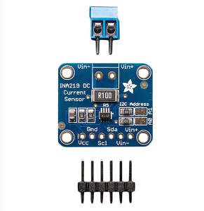 INA219 Current/Power Monitor: Features, Speicifications and Applications
24 May 20212484
 A Comprehensive Guide to LTC7138MPMSE#TRPBF DC-DC Switching Regulator
06 March 2024211
 Essential Tips for Resolving STM32F407ZET6 Connectivity Issues
24 July 2025360
![The Comprehensive Introduction to SS14 Diode [Video]](https://res.utmel.com/Images/Article/23a63ed5-220a-478b-94ec-1bf5079c2fd9.jpg) The Comprehensive Introduction to SS14 Diode [Video]
The Comprehensive Introduction to SS14 Diode [Video]02 September 20226293
![Difference Between BC547 Transistor vs. 2N2222 Transistor [Video&FAQ]](https://res.utmel.com/Images/Article/44f9ff79-5120-4f7d-bf83-d8602eca6431.jpg) Difference Between BC547 Transistor vs. 2N2222 Transistor [Video&FAQ]
Difference Between BC547 Transistor vs. 2N2222 Transistor [Video&FAQ]28 August 202337525
![1N4148WS-7-F Diode: Datasheet, Equivalent, Pinout [FAQ]](https://res.utmel.com/Images/Article/ba6694eb-7e58-4c6f-9508-4e03380f931a.jpg) 1N4148WS-7-F Diode: Datasheet, Equivalent, Pinout [FAQ]
1N4148WS-7-F Diode: Datasheet, Equivalent, Pinout [FAQ]24 April 20222616
 IXBK55N300 Monolithic Bipolar MOS Transistor: Package, Pinout, and Datasheet
01 March 2022667
 MID400 Optocoupler: Pinout, Datasheet and Applications
16 September 20212032
 Apple M1 Ultra -- The Technology Behind the Chip Interconnection
12 March 20226339
 Top 10 OSAT (Outsourced Semiconductor Assembly and Test) Companies
18 December 202562149
 Hot Swap Controllers:Semiconductors That Provide In-circuit Protection and Control Functions
22 February 20234212
 Intel Launches Industry's First Stackable, Shareable and Transferable One-Year Semiconductor Technician Certificate Program
26 September 20233002
 Comparison of Advantages and Disadvantages of Common Switch Mode Power Supply(SMPS)
21 January 20227587
![Basic Introduction to Digital Filter [Video]](https://res.utmel.com/Images/Article/b0245181-c936-414a-8241-51bf13e7c6b3.jpg) Basic Introduction to Digital Filter [Video]
Basic Introduction to Digital Filter [Video]23 October 20204468
 Analyzing Temperature Parameters of Si, SiC and GaN Power Devices
09 September 20231253
 Dismantling and Analyzing Each Component in the Switching Power Supply
16 February 20228002
STMicroelectronics
In Stock: 13
United States
China
Canada
Japan
Russia
Germany
United Kingdom
Singapore
Italy
Hong Kong(China)
Taiwan(China)
France
Korea
Mexico
Netherlands
Malaysia
Austria
Spain
Switzerland
Poland
Thailand
Vietnam
India
United Arab Emirates
Afghanistan
Åland Islands
Albania
Algeria
American Samoa
Andorra
Angola
Anguilla
Antigua & Barbuda
Argentina
Armenia
Aruba
Australia
Azerbaijan
Bahamas
Bahrain
Bangladesh
Barbados
Belarus
Belgium
Belize
Benin
Bermuda
Bhutan
Bolivia
Bonaire, Sint Eustatius and Saba
Bosnia & Herzegovina
Botswana
Brazil
British Indian Ocean Territory
British Virgin Islands
Brunei
Bulgaria
Burkina Faso
Burundi
Cabo Verde
Cambodia
Cameroon
Cayman Islands
Central African Republic
Chad
Chile
Christmas Island
Cocos (Keeling) Islands
Colombia
Comoros
Congo
Congo (DRC)
Cook Islands
Costa Rica
Côte d’Ivoire
Croatia
Cuba
Curaçao
Cyprus
Czechia
Denmark
Djibouti
Dominica
Dominican Republic
Ecuador
Egypt
El Salvador
Equatorial Guinea
Eritrea
Estonia
Eswatini
Ethiopia
Falkland Islands
Faroe Islands
Fiji
Finland
French Guiana
French Polynesia
Gabon
Gambia
Georgia
Ghana
Gibraltar
Greece
Greenland
Grenada
Guadeloupe
Guam
Guatemala
Guernsey
Guinea
Guinea-Bissau
Guyana
Haiti
Honduras
Hungary
Iceland
Indonesia
Iran
Iraq
Ireland
Isle of Man
Israel
Jamaica
Jersey
Jordan
Kazakhstan
Kenya
Kiribati
Kosovo
Kuwait
Kyrgyzstan
Laos
Latvia
Lebanon
Lesotho
Liberia
Libya
Liechtenstein
Lithuania
Luxembourg
Macao(China)
Madagascar
Malawi
Maldives
Mali
Malta
Marshall Islands
Martinique
Mauritania
Mauritius
Mayotte
Micronesia
Moldova
Monaco
Mongolia
Montenegro
Montserrat
Morocco
Mozambique
Myanmar
Namibia
Nauru
Nepal
New Caledonia
New Zealand
Nicaragua
Niger
Nigeria
Niue
Norfolk Island
North Korea
North Macedonia
Northern Mariana Islands
Norway
Oman
Pakistan
Palau
Palestinian Authority
Panama
Papua New Guinea
Paraguay
Peru
Philippines
Pitcairn Islands
Portugal
Puerto Rico
Qatar
Réunion
Romania
Rwanda
Samoa
San Marino
São Tomé & Príncipe
Saudi Arabia
Senegal
Serbia
Seychelles
Sierra Leone
Sint Maarten
Slovakia
Slovenia
Solomon Islands
Somalia
South Africa
South Sudan
Sri Lanka
St Helena, Ascension, Tristan da Cunha
St. Barthélemy
St. Kitts & Nevis
St. Lucia
St. Martin
St. Pierre & Miquelon
St. Vincent & Grenadines
Sudan
Suriname
Svalbard & Jan Mayen
Sweden
Syria
Tajikistan
Tanzania
Timor-Leste
Togo
Tokelau
Tonga
Trinidad & Tobago
Tunisia
Turkey
Turkmenistan
Turks & Caicos Islands
Tuvalu
U.S. Outlying Islands
U.S. Virgin Islands
Uganda
Ukraine
Uruguay
Uzbekistan
Vanuatu
Vatican City
Venezuela
Wallis & Futuna
Yemen
Zambia
Zimbabwe
![STM32F103RBT6]() STM32F103RBT6
STM32F103RBT6STMicroelectronics
![STM32F103ZET6]() STM32F103ZET6
STM32F103ZET6STMicroelectronics
![STM32H743IIT6]() STM32H743IIT6
STM32H743IIT6STMicroelectronics
![STM32F407VET6]() STM32F407VET6
STM32F407VET6STMicroelectronics
![STM32F405RGT6]() STM32F405RGT6
STM32F405RGT6STMicroelectronics
![STM32F030C8T6]() STM32F030C8T6
STM32F030C8T6STMicroelectronics
![STM32F100C8T6B]() STM32F100C8T6B
STM32F100C8T6BSTMicroelectronics
![STM32F103VBT6]() STM32F103VBT6
STM32F103VBT6STMicroelectronics
![STM8S003F3U6TR]() STM8S003F3U6TR
STM8S003F3U6TRSTMicroelectronics
![STM32F429ZIT6]() STM32F429ZIT6
STM32F429ZIT6STMicroelectronics


