
 Product
 Brand
Brand Articles
 Tools
Tools
CS4270 Stereo Audio CODEC: CS4270 Datasheet, Pinout, CS4272 VS. CS4270

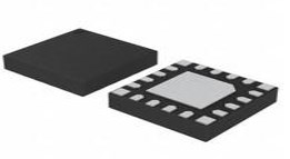
24 Termination 0.65mm 3.35V Tin CODEC CS4270 24 Pin 24-TSSOP (0.173, 4.40mm Width)
Unit Price: $5.400813
Ext Price: $5.40


24 Termination 0.65mm 3.35V Tin CODEC CS4270 24 Pin 24-TSSOP (0.173, 4.40mm Width)
The CS4270 is a high-performance, integrated audio CODEC. This article will unlock its datasheet, pinout, feature, application and more about CS4270.
CS4270 Pinout

CS4270 Pinout
CS4270 CAD Model
Symbol

CS4270 Symbol
Footprint

CS4270 Footprint
3D Model

CS4270 3D Model
CS4270 Description
The CS4270 is a high-performance, integrated audio CODEC. The CS4270 performs stereo analogue-to-digital (A/D) and digital-to-analog (D/A) conversion of up to 24-bit serial values at sample rates up to 216 kHz. Standard 50/15 µs de-emphasis is available for sampling rates of 44.1 kHz for compatibility with digital audio programs mastered using the 50/15 µs pre-emphasis technique.
Integrated level translators allow easy interfacing between the CS4270 and other devices operating over a wide range of logic levels.
Independently addressable high-pass filters are available for the right and left channels of the A/D. This allows the A/D to be used in a wide variety of applications where one audio channel and one DC measurement channel is desired.
The CS4270 is available in a 24-pin TSSOP package in both Commercial (-10° to +70° C) and Automotive grades (-40° to +85 ° C). The CDB4270 Customer Demonstration board is also available for device evaluation and implementation suggestions. Please refer to “Ordering Information” on page 47 for complete ordering information.
CS4270 Feature
System Features
– Serial Audio Port Master or Slave Operation
– Internal Digital Loopback Available
D/A Features
– Selectable Auto-mute
– 44.1 -kHz De-emphasis Filters
– Configurable Muting Controls
– Volume Control
– Selectable Serial Audio Interface Formats
• Left-Justified up to 24 -bit
• I²S up to 24 -bit
• Right-Justified 16, and 24 -bit
A/D Features
– Selectable High-Pass Filter or DC Offset Calibration
– Selectable Serial Audio Interface Formats
• Left-Justified up to 24 -bit
• I²S up to 24 -bit
CS4270 Block Diagram
The following figure shows the block diagram of CS4270

CS4270 Block Diagram
CS4270 Application
DVD recorders
Digital televisions
Set-top boxes
Effects processors
Automotive audio systems
CS4270 Typical Diagram
CS4270 Typical Connection Diagram is given below

CS4270 Typical Connection Diagram
CS4270 Package

CS4270 Package
CS4270 Manufacturer
Cirrus Logic is a leader in high performance, low-power ICs for audio and voice signal processing applications. Cirrus Logic ¿s products span the entire audio signal chain, from capture to playback, providing innovative products for the world¿s top smartphones, tablets, digital headsets, wearables and emerging smart home applications. With headquarters in Austin, Texas, Cirrus Logic is recognised globally for its award-winning corporate culture.
Specifications
- TypeParameter
- Factory Lead Time19 Weeks
- Contact Plating
Contact plating (finish) provides corrosion protection for base metals and optimizes the mechanical and electrical properties of the contact interfaces.
Tin - Mount
In electronic components, the term "Mount" typically refers to the method or process of physically attaching or fixing a component onto a circuit board or other electronic device. This can involve soldering, adhesive bonding, or other techniques to secure the component in place. The mounting process is crucial for ensuring proper electrical connections and mechanical stability within the electronic system. Different components may have specific mounting requirements based on their size, shape, and function, and manufacturers provide guidelines for proper mounting procedures to ensure optimal performance and reliability of the electronic device.
Surface Mount - Mounting Type
The "Mounting Type" in electronic components refers to the method used to attach or connect a component to a circuit board or other substrate, such as through-hole, surface-mount, or panel mount.
Surface Mount - Package / Case
refers to the protective housing that encases an electronic component, providing mechanical support, electrical connections, and thermal management.
24-TSSOP (0.173, 4.40mm Width) - Number of Pins24
- Weight211.997734mg
- Usage LevelCommercial grade
- Operating Temperature
The operating temperature is the range of ambient temperature within which a power supply, or any other electrical equipment, operate in. This ranges from a minimum operating temperature, to a peak or maximum operating temperature, outside which, the power supply may fail.
-10°C~70°C - Packaging
Semiconductor package is a carrier / shell used to contain and cover one or more semiconductor components or integrated circuits. The material of the shell can be metal, plastic, glass or ceramic.
Tube - Published1995
- JESD-609 Code
The "JESD-609 Code" in electronic components refers to a standardized marking code that indicates the lead-free solder composition and finish of electronic components for compliance with environmental regulations.
e3 - Pbfree Code
The "Pbfree Code" parameter in electronic components refers to the code or marking used to indicate that the component is lead-free. Lead (Pb) is a toxic substance that has been widely used in electronic components for many years, but due to environmental concerns, there has been a shift towards lead-free alternatives. The Pbfree Code helps manufacturers and users easily identify components that do not contain lead, ensuring compliance with regulations and promoting environmentally friendly practices. It is important to pay attention to the Pbfree Code when selecting electronic components to ensure they meet the necessary requirements for lead-free applications.
yes - Part Status
Parts can have many statuses as they progress through the configuration, analysis, review, and approval stages.
Active - Moisture Sensitivity Level (MSL)
Moisture Sensitivity Level (MSL) is a standardized rating that indicates the susceptibility of electronic components, particularly semiconductors, to moisture-induced damage during storage and the soldering process, defining the allowable exposure time to ambient conditions before they require special handling or baking to prevent failures
3 (168 Hours) - Number of Terminations24
- Termination
Termination in electronic components refers to the practice of matching the impedance of a circuit to prevent signal reflections and ensure maximum power transfer. It involves the use of resistors or other components at the end of transmission lines or connections. Proper termination is crucial in high-frequency applications to maintain signal integrity and reduce noise.
SMD/SMT - TypeStereo Audio
- Terminal Position
In electronic components, the term "Terminal Position" refers to the physical location of the connection points on the component where external electrical connections can be made. These connection points, known as terminals, are typically used to attach wires, leads, or other components to the main body of the electronic component. The terminal position is important for ensuring proper connectivity and functionality of the component within a circuit. It is often specified in technical datasheets or component specifications to help designers and engineers understand how to properly integrate the component into their circuit designs.
DUAL - Terminal Form
Occurring at or forming the end of a series, succession, or the like; closing; concluding.
GULL WING - Peak Reflow Temperature (Cel)
Peak Reflow Temperature (Cel) is a parameter that specifies the maximum temperature at which an electronic component can be exposed during the reflow soldering process. Reflow soldering is a common method used to attach electronic components to a circuit board. The Peak Reflow Temperature is crucial because it ensures that the component is not damaged or degraded during the soldering process. Exceeding the specified Peak Reflow Temperature can lead to issues such as component failure, reduced performance, or even permanent damage to the component. It is important for manufacturers and assemblers to adhere to the recommended Peak Reflow Temperature to ensure the reliability and functionality of the electronic components.
NOT SPECIFIED - Number of Functions1
- Terminal Pitch
The center distance from one pole to the next.
0.65mm - Time@Peak Reflow Temperature-Max (s)
Time@Peak Reflow Temperature-Max (s) refers to the maximum duration that an electronic component can be exposed to the peak reflow temperature during the soldering process, which is crucial for ensuring reliable solder joint formation without damaging the component.
NOT SPECIFIED - Base Part Number
The "Base Part Number" (BPN) in electronic components serves a similar purpose to the "Base Product Number." It refers to the primary identifier for a component that captures the essential characteristics shared by a group of similar components. The BPN provides a fundamental way to reference a family or series of components without specifying all the variations and specific details.
CS4270 - Pin Count
a count of all of the component leads (or pins)
24 - Qualification Status
An indicator of formal certification of qualifications.
Not Qualified - Power Supplies
an electronic circuit that converts the voltage of an alternating current (AC) into a direct current (DC) voltage.?
3.35V - Interface
In electronic components, the term "Interface" refers to the point at which two different systems, devices, or components connect and interact with each other. It can involve physical connections such as ports, connectors, or cables, as well as communication protocols and standards that facilitate the exchange of data or signals between the connected entities. The interface serves as a bridge that enables seamless communication and interoperability between different parts of a system or between different systems altogether. Designing a reliable and efficient interface is crucial in ensuring proper functionality and performance of electronic components and systems.
I2C, SPI, Serial - Max Supply Voltage
In general, the absolute maximum common-mode voltage is VEE-0.3V and VCC+0.3V, but for products without a protection element at the VCC side, voltages up to the absolute maximum rated supply voltage (i.e. VEE+36V) can be supplied, regardless of supply voltage.
5.25V - Min Supply Voltage
The minimum supply voltage (V min ) is explored for sequential logic circuits by statistically simulating the impact of within-die process variations and gate-dielectric soft breakdown on data retention and hold time.
3.1V - Nominal Supply Current
Nominal current is the same as the rated current. It is the current drawn by the motor while delivering rated mechanical output at its shaft.
31mA - Data Interface
A Data Interface in EDQ is a template of a set of attributes representing a given entity, used to create processes that read from, or write to, interfaces rather than directly from or to sources or targets of data.
Serial - Sampling Rate
often described in the context of signal processing as the number of samples per time.
192 ksps - Voltage - Supply, Analog
Voltage - Supply, Analog is a parameter in electronic components that specifies the range of voltage levels required to power the analog circuitry within the component. This parameter indicates the minimum and maximum voltage levels that the component can accept for proper operation of its analog functions. It is crucial to ensure that the voltage supplied to the component falls within this specified range to prevent damage and ensure optimal performance. Understanding and adhering to the "Voltage - Supply, Analog" parameter is essential for the proper functioning of analog circuits in electronic components.
3.14V~5.25V - Voltage - Supply, Digital
Voltage - Supply, Digital is a parameter that specifies the voltage level required to power the digital circuitry within an electronic component, such as an integrated circuit or a microcontroller. This parameter is crucial for ensuring proper operation of the digital components, as supplying the correct voltage level is essential for reliable performance. The specified voltage range typically includes both minimum and maximum values within which the component can operate safely and efficiently. It is important to adhere to the recommended voltage supply range to prevent damage to the component and to maintain the integrity of the digital signals being processed.
3.14V~5.25V - Number of D/A Converters1
- Resolution (Bits)
Resolution (Bits) in electronic components refers to the number of bits used to represent the analog signal in digital form. It indicates the level of detail or precision with which the analog signal can be converted into digital data. A higher resolution means more bits are used, allowing for finer distinctions to be made between different signal levels. For example, an 8-bit resolution can represent 256 different levels, while a 16-bit resolution can represent 65,536 levels. In general, a higher resolution leads to better accuracy and fidelity in the digital representation of the original analog signal.
24 b - Sigma Delta
In electronic components, "Sigma Delta" refers to a type of analog-to-digital converter (ADC) architecture commonly used in applications requiring high resolution and low noise. The Sigma Delta ADC works by oversampling the input signal at a much higher frequency than the desired output rate, and then using a digital filter to reduce the noise and quantization errors. This approach allows for achieving high resolution with relatively simple analog circuitry. The name "Sigma Delta" comes from the use of sigma (Σ) for the oversampling and delta (Δ) for the quantization error feedback mechanism. Overall, Sigma Delta ADCs are known for their ability to provide high-resolution conversion with low noise and are commonly used in audio, instrumentation, and sensor applications.
Yes - Number of ADCs / DACs2 / 2
- Dynamic Range, ADCs / DACs (db) Typ
The parameter "Dynamic Range, ADCs / DACs (db) Typ" in electronic components refers to the range of signal amplitudes that can be accurately measured or reproduced by an analog-to-digital converter (ADC) or digital-to-analog converter (DAC). It is typically expressed in decibels (dB) and represents the ratio between the largest and smallest signals that can be effectively processed by the ADC or DAC without distortion or loss of accuracy. A higher dynamic range indicates a greater ability to capture or reproduce a wide range of signal amplitudes, making the component more versatile and suitable for applications requiring precise signal processing. It is an important specification to consider when selecting ADCs or DACs for audio, video, communications, and other high-fidelity applications.
105 / 105 - Height900μm
- Length7.8mm
- Width4.4mm
- REACH SVHC
The parameter "REACH SVHC" in electronic components refers to the compliance with the Registration, Evaluation, Authorization, and Restriction of Chemicals (REACH) regulation regarding Substances of Very High Concern (SVHC). SVHCs are substances that may have serious effects on human health or the environment, and their use is regulated under REACH to ensure their safe handling and minimize their impact.Manufacturers of electronic components need to declare if their products contain any SVHCs above a certain threshold concentration and provide information on the safe use of these substances. This information allows customers to make informed decisions about the potential risks associated with using the components and take appropriate measures to mitigate any hazards.Ensuring compliance with REACH SVHC requirements is essential for electronics manufacturers to meet regulatory standards, protect human health and the environment, and maintain transparency in their supply chain. It also demonstrates a commitment to sustainability and responsible manufacturing practices in the electronics industry.
No SVHC - RoHS Status
RoHS means “Restriction of Certain Hazardous Substances” in the “Hazardous Substances Directive” in electrical and electronic equipment.
RoHS Compliant - Lead Free
Lead Free is a term used to describe electronic components that do not contain lead as part of their composition. Lead is a toxic material that can have harmful effects on human health and the environment, so the electronics industry has been moving towards lead-free components to reduce these risks. Lead-free components are typically made using alternative materials such as silver, copper, and tin. Manufacturers must comply with regulations such as the Restriction of Hazardous Substances (RoHS) directive to ensure that their products are lead-free and environmentally friendly.
Lead Free
Parts with Similar Specs
- ImagePart NumberManufacturerPackage / CaseNumber of PinsInterfaceNumber of D/A ConvertersMin Supply VoltageMax Supply VoltageTerminal PositionPbfree CodeView Compare
![CS4270-CZZ]()
CS4270-CZZ
24-TSSOP (0.173, 4.40mm Width)
24
I2C, SPI, Serial
1
3.1 V
5.25 V
DUAL
yes
![PCM3060PW]()
28-TSSOP (0.173, 4.40mm Width)
28
I2C, I2S, SPI, Serial
-
2.37 V
5.25 V
DUAL
yes
![PCM3060PWR]()
28-TSSOP (0.173, 4.40mm Width)
28
I2C, SPI, Serial
-
2.37 V
5.25 V
DUAL
yes
![CS4271-CZZ]()
28-TSSOP (0.173, 4.40mm Width)
28
2-Wire, I2C, SPI, Serial
-
4.5 V
5.5 V
DUAL
yes
![CS4272-CZZ]()
28-TSSOP (0.173, 4.40mm Width)
28
2-Wire, I2C, SPI, Serial
-
4.5 V
5.5 V
DUAL
yes


Datasheet PDF
- Datasheets :
- PCN Packaging :
- PCN Assembly/Origin :
Trend Analysis
What allows easy interfacing between the CS4270 and other devices operating over a wide range of logic levels?
Integrated level translators.
What is available for the right and left channels of the A/D?
Independently addressable high-pass filters.
What type of package is the CS4270 available in?
24-pin TSSOP.
What board is available for device evaluation and implementation suggestions?
CDB4270 Customer Demonstration board.
What supports operation in either Master Mode or Slave Mode?
CS4270.
What mode does the CS4270 enter Slave Mode when SDOUT is pulled low through a 47 k resistor?
Stand-Alone Mode.
![MAC97A6 Triac: Circuit, Pinout, and Datasheet [Video&FAQ]](https://res.utmel.com/Images/Article/3d2e9f53-37e8-4618-aa51-5ebefcc79230.png) MAC97A6 Triac: Circuit, Pinout, and Datasheet [Video&FAQ]
MAC97A6 Triac: Circuit, Pinout, and Datasheet [Video&FAQ]10 November 202126526
 SI5351 Clock Generator: Datasheet, Pinout and Applications
31 August 20217108
 HMC Series (Hittite/ADI): High-Frequency RF and Microwave IC Design Guide
15 January 2026530
 MTFC8GAKAJCN-4M IT Flash Card 8G-byte 3.3V 153-Pin VFBGA: Datasheet, Pinout, and Equivalents
14 February 20222479
![CD4007 CMOS Inverter: 14 SOIC Inverter, Pinout and Datasheet pdf [Video]](https://res.utmel.com/Images/Article/c2022e28-6851-4487-8983-58a7ba99db80.jpg) CD4007 CMOS Inverter: 14 SOIC Inverter, Pinout and Datasheet pdf [Video]
CD4007 CMOS Inverter: 14 SOIC Inverter, Pinout and Datasheet pdf [Video]07 January 20227296
 LTC7545ABSW#TRPBF Digital to Analog Converter: Product Overview and Applications
06 March 2024172
 SC811 / SC813 Tri-Mode Adapter/USB:Pinout,Datasheet,Features
17 September 2021394
 megaAVR® 0-series 20MHz 8-bit MCU: Datasheet, UPDI, and Performance Deep Dive
06 February 2026209
 RF Front End in the 5G Era
25 October 20217496
 Using SiC-GaN to Create Two-Phase Interleaved DC-DC Converters for Plug-in Electric Vehicles
03 February 20232881
 Three-Level Integration of Circuits
05 May 20223778
 Use of WBG Semiconductor Power Converters in DC Microgrid Applications
12 December 20232479
 What is Flexible Sensor?
30 May 20225626
 Things You Need to Know about Seven-segment Display
14 October 20217858
 What is a Knock Sensor?
08 January 202619945
 SR626SW Battery Equivalent: Technical Specs, Chemistries, and Selection Guide
26 May 2026820
Cirrus Logic Inc.
In Stock: 4000
Minimum: 1 Multiples: 1
Qty
Unit Price
Ext Price
1
$5.400813
$5.40
10
$5.095107
$50.95
100
$4.806704
$480.67
500
$4.534627
$2,267.31
1000
$4.277950
$4,277.95
Not the price you want? Send RFQ Now and we'll contact you ASAP.
Inquire for More Quantity
![CS4245-CQZ]() CS4245-CQZ
CS4245-CQZCirrus Logic Inc.
![WM8960CGEFL/V]() WM8960CGEFL/V
WM8960CGEFL/VCirrus Logic Inc.
![CS42L51-CNZR]() CS42L51-CNZR
CS42L51-CNZRCirrus Logic Inc.
![WM8994ECS/R]() WM8994ECS/R
WM8994ECS/RCirrus Logic Inc.
![CS4271-CZZ]() CS4271-CZZ
CS4271-CZZCirrus Logic Inc.
![CS4271-CZZR]() CS4271-CZZR
CS4271-CZZRCirrus Logic Inc.
![CS4207-CNZ]() CS4207-CNZ
CS4207-CNZCirrus Logic Inc.
![WM9713CLGEFL/RV]() WM9713CLGEFL/RV
WM9713CLGEFL/RVCirrus Logic Inc.
![WM8940CGEFL/RV]() WM8940CGEFL/RV
WM8940CGEFL/RVCirrus Logic Inc.
![WM8974CGEFL/RV]() WM8974CGEFL/RV
WM8974CGEFL/RVCirrus Logic Inc.


