
How to Integrate EPC2LI20N into Your Circuit Design

Surface Mount 1.6Mb Mb Tray Configuration Proms for FPGAs 3 (168 Hours) In System Programmable EPC Obsolete EPC2 compliant


Surface Mount 1.6Mb Mb Tray Configuration Proms for FPGAs 3 (168 Hours) In System Programmable EPC Obsolete EPC2 compliant
Integrate the EPC2LI20N into your circuit design with ease. Learn its key features, setup tools, and step-by-step process for seamless FPGA configuration.
Product Introduction
The EPC2LI20N is a versatile configuration device widely used in circuit designs. It plays a critical role in managing in-system programming, allowing you to program circuits directly without removing components. This feature enhances efficiency during development. Moreover, its dynamic reconfiguration capabilities enable you to adapt your design to changing requirements, making it ideal for complex projects.
By understanding the EPC2LI20N's functionality, you can integrate it seamlessly into your circuits. This blog provides practical steps to help you maximize its potential in your designs.
Understanding EPC2LI20N Specifications
Key Features of EPC2LI20N
The EPC2LI20N offers several features that make it a standout choice for FPGA configuration. Its high-density design supports 6,000 to 12,000 usable gates, making it suitable for complex circuit designs. You can benefit from its fast pin-to-pin delays of 10 nanoseconds and counter speeds reaching up to 144 MHz. These specifications ensure efficient performance in time-sensitive applications.
Another key feature is its in-system programmability (ISP). This allows you to program the device directly through a built-in JTAG interface, eliminating the need for external programming tools. Additionally, the EPC2LI20N complies with the PCI Local Bus Specification, Revision 2.2, ensuring compatibility with modern systems. Its programmable output slew-rate control reduces switching noise, which is crucial for maintaining signal integrity in high-speed circuits.
EPC2LI20N Technical Specifications
Understanding the technical specifications of the EPC2LI20N is essential for successful integration. Below is a detailed table summarizing its key specifications:
| Specification | Value |
|---|---|
| Memory Type | Flash |
| Memory Size | 1.6 Mbit |
| Operating Frequency | 10 MHz |
| Supply Voltage - Max | 5.25 V |
| Supply Voltage - Min | 3 V |
| Supply Current | 50 uA |
| Maximum Operating Temperature | + 85℃ |
| Minimum Operating Temperature | - 40℃ |
| Mounting Style | SMD/SMT |
| Package / Case | PLCC-20 |
| Packaging | Tube |
| Series | EPC2 |
These specifications highlight the EPC2LI20N's reliability and versatility in various environments. Its wide operating temperature range and low power consumption make it ideal for industrial and consumer applications.
EPC2LI20 vs EPC2LI20N: Key Differences
When comparing the EPC2LI20 and EPC2LI20N, you’ll notice several similarities and a few critical differences. Both models share the same memory size of 1.6 Mbit, maximum operating frequency of 10 MHz, and package type (PLCC-20). However, the EPC2LI20N is RoHS-compliant, making it environmentally friendly and suitable for modern manufacturing standards. Additionally, the EPC2LI20N has a unique orderable part number (972061) compared to the EPC2LI20 (974534).
Here’s a quick comparison table for clarity:
| Specification | EPC2LI20 | EPC2LI20N |
|---|---|---|
| Manufacturer | Intel | Intel |
| Package | PLCC-20 | PLCC-20 |
| Memory Size | 1.6 Mbit | 1.6 Mbit |
| Maximum Operating Frequency | 10 MHz | 10 MHz |
| RoHS | No | Yes |
| Current @ Pmpp | 50 uA | 50 uA |
| Supply Voltage - Min | 3 V | 3 V |
| Max Supply Voltage | 5.25 V | 5.25 V |
| Tradename | Enpirion | Enpirion |
| Orderable part number | 974534 | 972061 |
The EPC2LI20N’s compliance with RoHS and its updated part number make it a better choice for new designs. These differences, while subtle, can significantly impact your project’s compatibility and sustainability.
Preparing for Integration
Tools and Software for EPC2LI20N Integration
To integrate the EPC2LI20N into your circuit design, you need the right tools and software. Start with a reliable hardware programmer that supports in-system programming. Devices like USB Blaster or similar JTAG-compatible programmers work well. These tools allow you to program the EPC2LI20N directly on your circuit board.
For software, use Intel's Quartus Prime. This tool simplifies the configuration process and ensures compatibility with the EPC2LI20 series. Quartus Prime provides a user-friendly interface for creating, simulating, and programming your designs. Additionally, download the EPC2LI20N-specific configuration files from Intel's official website. These files ensure that your software recognizes the device and applies the correct settings.
Keep a multimeter and an oscilloscope handy. These tools help you verify connections and monitor signals during the integration process. A soldering station with fine tips is also essential for precise work, especially if you're dealing with the PLCC-20 package.
Compatible Components for EPC2LI20N
Choosing compatible components ensures seamless integration. The EPC2LI20N works well with FPGAs from Intel's Cyclone and Stratix series. These FPGAs complement the EPC2LI20N's configuration capabilities, making them ideal for complex designs.
For power supply, use a voltage regulator that provides a stable output between 3V and 5.25V. This range matches the EPC2LI20N's operating requirements. Select capacitors with low equivalent series resistance (ESR) to filter noise and maintain signal integrity. Resistors with precise tolerances are also crucial for ensuring stable operation.
When selecting connectors, opt for JTAG-compatible headers. These connectors simplify programming and debugging. Ensure that all components meet the RoHS compliance standards if you're designing for modern manufacturing.
Setting Up Your Workspace for EPC2LI20N Projects
A well-organized workspace improves efficiency and reduces errors. Begin by setting up an anti-static mat and wrist strap to protect the EPC2LI20N and other sensitive components from electrostatic discharge. Arrange your tools and components within easy reach to streamline your workflow.
Use a magnifying lamp or microscope for detailed work. This is especially helpful when soldering the PLCC-20 package. Label your components and tools to avoid confusion during the assembly process.
Create a dedicated area for testing and debugging. Equip this space with your multimeter, oscilloscope, and power supply. Ensure that your workspace has adequate lighting and ventilation to maintain a comfortable working environment.
Tip: Keep a notebook or digital log to document your progress. Recording your steps helps you troubleshoot issues and replicate successful setups in future projects.
Step-by-Step Integration Process
Initial Setup and Configuration of EPC2LI20N
Before integrating the EPC2LI20N into your circuit, you need to configure it properly. Start by downloading the latest configuration files from Intel's official website. These files ensure compatibility with your FPGA and simplify the programming process. Use Intel's Quartus Prime software to load these files and prepare the device for integration.
Next, connect your EPC2LI20N to a JTAG-compatible programmer like the USB Blaster. Ensure the programmer is correctly installed on your computer. Open Quartus Prime and select the EPC2LI20N as the target device. Follow the on-screen instructions to load the configuration file onto the device. This step programs the EPC2LI20N with the necessary data to communicate with your FPGA.
After programming, verify the configuration by running a quick test. Use the software's built-in diagnostic tools to check for errors. If the test passes, your EPC2LI20N is ready for integration.
Tip: Always double-check the configuration file version before programming. Using outdated files can cause compatibility issues with your FPGA.
Connecting EPC2LI20N to Your Circuit
Connecting the EPC2LI20N to your circuit requires careful planning. Begin by identifying the pinout of the PLCC-20 package. Refer to the datasheet for a detailed diagram. Match the pins on the EPC2LI20N to the corresponding connections on your circuit board.
Use a soldering station with a fine tip to attach the EPC2LI20N to the board. Apply a small amount of solder to each pin to ensure a secure connection. Avoid using excessive solder, as this can cause short circuits.
When connecting the EPC2LI20N to your FPGA, pay attention to the JTAG interface. This interface allows the two devices to communicate during programming and operation. Use a JTAG-compatible header to simplify the connection process. Ensure the header is securely attached to both the EPC2LI20N and the FPGA.
Here are some best practices for effective connections:
Use low-resistance wires to minimize signal loss.
Place decoupling capacitors near the power pins to filter noise.
Verify the connections with a multimeter before powering the circuit.
These steps align with the comparison of EPC2LI20 and EPC2LI20N. The analysis highlights features like memory type, package type, and RoHS compliance, which simplify component selection and ensure compatibility with various circuit designs.
Testing and Verifying EPC2LI20N Functionality
Testing the EPC2LI20N ensures it functions correctly within your circuit. Begin by powering the circuit and monitoring the voltage levels. Use a multimeter to check that the supply voltage falls within the 3V to 5.25V range specified in the datasheet.
Next, test the communication between the EPC2LI20N and your FPGA. Use Quartus Prime to send a test signal through the JTAG interface. Monitor the response from the FPGA to confirm that the configuration data is being transmitted correctly.
If you encounter issues, use an oscilloscope to analyze the signal integrity. Look for any irregularities in the waveform that could indicate a problem. Common issues include noise, incorrect voltage levels, or poor solder connections.
Finally, run a functional test of your circuit. Load a simple program onto the FPGA and observe its behavior. If the circuit operates as expected, the EPC2LI20N is functioning correctly.
Note: Document your test results for future reference. This practice helps you identify patterns and troubleshoot more effectively in future projects.
Common Challenges and Solutions
Troubleshooting EPC2LI20N Connection Issues
When working with the EPC2LI20N, connection issues can arise due to improper soldering, incorrect pin mapping, or faulty components. These problems can disrupt communication between the device and your circuit, leading to errors during programming or operation.
To troubleshoot these issues, follow these steps:
Inspect the Solder Joints: Use a magnifying glass to check for cold solder joints or bridges between pins. Resolder any problematic connections.
Verify Pin Mapping: Cross-check the pinout diagram in the datasheet with your circuit design. Ensure each pin is connected to the correct signal or power source.
Test Continuity: Use a multimeter to confirm that all connections are intact. Check for unexpected shorts between adjacent pins.
Replace Faulty Components: If the above steps don’t resolve the issue, test the EPC2LI20N on a different board. This helps identify whether the problem lies with the device or the circuit.
Tip: Always handle the EPC2LI20N with an anti-static wrist strap to prevent damage from electrostatic discharge.
Resolving EPC2LI20N Compatibility Problems
Compatibility problems often occur when the EPC2LI20N is paired with unsupported components or outdated software. These issues can prevent the device from functioning as intended in your circuit.
Here’s how you can address compatibility challenges:
Update Your Software: Ensure you’re using the latest version of Intel’s Quartus Prime. Older versions may lack support for the EPC2LI20N or its configuration files.
Check Component Compatibility: Use FPGAs from Intel’s Cyclone or Stratix series, as these are known to work seamlessly with the EPC2LI20N. Avoid mixing components from different manufacturers unless compatibility is explicitly stated.
Review Voltage Requirements: Confirm that your power supply matches the EPC2LI20N’s operating range of 3V to 5.25V. Voltage mismatches can cause erratic behavior or permanent damage.
Test with a Known Good Setup: If you suspect compatibility issues, test the EPC2LI20N in a circuit that has been verified to work. This helps isolate the problem.
Note: Always download configuration files directly from Intel’s official website to avoid corrupted or outdated versions.
Ensuring Reliable Performance of EPC2LI20N
To achieve reliable performance, you must optimize your circuit design and maintain the EPC2LI20N under ideal operating conditions. Neglecting these factors can lead to inconsistent behavior or reduced lifespan.
Follow these best practices to ensure reliability:
Use Decoupling Capacitors: Place capacitors near the power pins to stabilize the voltage supply and filter out noise.
Minimize Signal Interference: Route high-speed signals away from the EPC2LI20N to reduce electromagnetic interference. Use ground planes to shield sensitive traces.
Monitor Operating Conditions: Keep the device within its specified temperature range (-40℃ to +85℃). Use a heat sink or cooling fan if your circuit generates significant heat.
Regularly Test the Configuration: Periodically reprogram the EPC2LI20N to verify that the configuration data remains intact. This is especially important in environments with high levels of electrical noise.
Pro Tip: Document your circuit’s performance over time. This helps you identify trends and address potential issues before they escalate.
Conclusion and Best Practices
Key Takeaways for EPC2LI20N Integration
Integrating the EPC2LI20N into your circuit design requires careful planning and execution. You should start by understanding its specifications and features. This knowledge helps you select compatible components and tools. Preparing your workspace with anti-static measures and organized tools ensures efficiency during assembly. Following a structured process for setup, connection, and testing minimizes errors and saves time.
Testing the device thoroughly is essential. Use tools like multimeters and oscilloscopes to verify connections and monitor signals. Documenting your progress and test results helps you troubleshoot issues and replicate successful setups. By following these steps, you can achieve a reliable and efficient configuration for your circuit.
Tips for Long-Term EPC2LI20N Reliability
Maintaining the EPC2LI20N’s reliability over time involves optimizing your circuit design and monitoring its operating conditions. You should use decoupling capacitors to stabilize voltage and reduce noise. Routing high-speed signals away from the device prevents interference. Keeping the device within its specified temperature range ensures consistent performance.
Regular testing and reprogramming of the configuration data help maintain functionality. You should also inspect solder joints periodically to ensure connections remain intact. Documenting performance trends allows you to address potential issues before they escalate. These practices extend the lifespan of the EPC2LI20N and improve the reliability of your circuit.
Resources for Learning More About EPC2LI20N
Expanding your knowledge about the EPC2LI20N enhances your ability to use it effectively. Intel’s official website provides datasheets, configuration files, and user guides. You can also explore forums and communities dedicated to FPGA and circuit design. These platforms offer valuable insights and troubleshooting tips.
Books and online courses on FPGA programming and circuit design provide a deeper understanding of configuration devices like the EPC2LI20N. You should also consider attending workshops or webinars hosted by industry experts. These resources help you stay updated on best practices and emerging technologies.
Tip: Bookmark Intel’s support page for quick access to updates and technical assistance.
Understanding the EPC2LI20N’s specifications is essential for successful integration. It helps you select the right tools, components, and configurations for your project. Preparing adequately ensures a smoother workflow and reduces the risk of errors.
Following a structured process simplifies the integration. It allows you to connect, test, and verify the device efficiently. Each step builds on the last, ensuring a reliable outcome.
Remember: Applying best practices like using decoupling capacitors, monitoring operating conditions, and documenting progress enhances long-term reliability. By doing so, you can maximize the EPC2LI20N’s potential in your designs. 😊
FAQ
What is the primary function of the EPC2LI20N?
The EPC2LI20N stores configuration data for FPGAs. It enables in-system programming and dynamic reconfiguration, allowing you to update or modify your circuit design without removing components. This makes it ideal for flexible and efficient designs.
Can I use the EPC2LI20N with non-Intel FPGAs?
No, the EPC2LI20N is designed specifically for Intel FPGAs, such as the Cyclone and Stratix series. Using it with non-Intel FPGAs may cause compatibility issues. Always check the datasheet for supported devices.
How do I ensure proper soldering of the EPC2LI20N?
Use a fine-tip soldering iron and apply a small amount of solder to each pin. Avoid excessive solder to prevent short circuits. A magnifying lamp helps you inspect the connections for accuracy.
What tools are essential for testing the EPC2LI20N?
You need a multimeter to check voltage levels and an oscilloscope to analyze signal integrity. Intel’s Quartus Prime software is also essential for programming and testing the device.
Where can I find official resources for the EPC2LI20N?
Visit Intel’s official website for datasheets, configuration files, and user guides. These resources provide accurate and up-to-date information to help you integrate the EPC2LI20N effectively.
Tip: Bookmark Intel’s support page for quick access to updates and technical assistance.
Specifications
- TypeParameter
- Mounting Type
The "Mounting Type" in electronic components refers to the method used to attach or connect a component to a circuit board or other substrate, such as through-hole, surface-mount, or panel mount.
Surface Mount - Package / Case
refers to the protective housing that encases an electronic component, providing mechanical support, electrical connections, and thermal management.
20-LCC (J-Lead) - Surface Mount
having leads that are designed to be soldered on the side of a circuit board that the body of the component is mounted on.
YES - Operating Temperature
The operating temperature is the range of ambient temperature within which a power supply, or any other electrical equipment, operate in. This ranges from a minimum operating temperature, to a peak or maximum operating temperature, outside which, the power supply may fail.
-40°C~85°C - Packaging
Semiconductor package is a carrier / shell used to contain and cover one or more semiconductor components or integrated circuits. The material of the shell can be metal, plastic, glass or ceramic.
Tray - Series
In electronic components, the "Series" refers to a group of products that share similar characteristics, designs, or functionalities, often produced by the same manufacturer. These components within a series typically have common specifications but may vary in terms of voltage, power, or packaging to meet different application needs. The series name helps identify and differentiate between various product lines within a manufacturer's catalog.
EPC - JESD-609 Code
The "JESD-609 Code" in electronic components refers to a standardized marking code that indicates the lead-free solder composition and finish of electronic components for compliance with environmental regulations.
e3 - Part Status
Parts can have many statuses as they progress through the configuration, analysis, review, and approval stages.
Obsolete - Moisture Sensitivity Level (MSL)
Moisture Sensitivity Level (MSL) is a standardized rating that indicates the susceptibility of electronic components, particularly semiconductors, to moisture-induced damage during storage and the soldering process, defining the allowable exposure time to ambient conditions before they require special handling or baking to prevent failures
3 (168 Hours) - Number of Terminations20
- ECCN Code
An ECCN (Export Control Classification Number) is an alphanumeric code used by the U.S. Bureau of Industry and Security to identify and categorize electronic components and other dual-use items that may require an export license based on their technical characteristics and potential for military use.
EAR99 - Terminal Finish
Terminal Finish refers to the surface treatment applied to the terminals or leads of electronic components to enhance their performance and longevity. It can improve solderability, corrosion resistance, and overall reliability of the connection in electronic assemblies. Common finishes include nickel, gold, and tin, each possessing distinct properties suitable for various applications. The choice of terminal finish can significantly impact the durability and effectiveness of electronic devices.
Matte Tin (Sn) - Additional Feature
Any Feature, including a modified Existing Feature, that is not an Existing Feature.
IT CAN ALSO OPERATE AT 5V SUPPLY - HTS Code
HTS (Harmonized Tariff Schedule) codes are product classification codes between 8-1 digits. The first six digits are an HS code, and the countries of import assign the subsequent digits to provide additional classification. U.S. HTS codes are 1 digits and are administered by the U.S. International Trade Commission.
8542.32.00.51 - Voltage - Supply
Voltage - Supply refers to the range of voltage levels that an electronic component or circuit is designed to operate with. It indicates the minimum and maximum supply voltage that can be applied for the device to function properly. Providing supply voltages outside this range can lead to malfunction, damage, or reduced performance. This parameter is critical for ensuring compatibility between different components in a circuit.
3V~3.6V 4.5V~5.5V - Terminal Position
In electronic components, the term "Terminal Position" refers to the physical location of the connection points on the component where external electrical connections can be made. These connection points, known as terminals, are typically used to attach wires, leads, or other components to the main body of the electronic component. The terminal position is important for ensuring proper connectivity and functionality of the component within a circuit. It is often specified in technical datasheets or component specifications to help designers and engineers understand how to properly integrate the component into their circuit designs.
QUAD - Terminal Form
Occurring at or forming the end of a series, succession, or the like; closing; concluding.
J BEND - Peak Reflow Temperature (Cel)
Peak Reflow Temperature (Cel) is a parameter that specifies the maximum temperature at which an electronic component can be exposed during the reflow soldering process. Reflow soldering is a common method used to attach electronic components to a circuit board. The Peak Reflow Temperature is crucial because it ensures that the component is not damaged or degraded during the soldering process. Exceeding the specified Peak Reflow Temperature can lead to issues such as component failure, reduced performance, or even permanent damage to the component. It is important for manufacturers and assemblers to adhere to the recommended Peak Reflow Temperature to ensure the reliability and functionality of the electronic components.
245 - Number of Functions1
- Supply Voltage
Supply voltage refers to the electrical potential difference provided to an electronic component or circuit. It is crucial for the proper operation of devices, as it powers their functions and determines performance characteristics. The supply voltage must be within specified limits to ensure reliability and prevent damage to components. Different electronic devices have specific supply voltage requirements, which can vary widely depending on their design and intended application.
3.3V - Terminal Pitch
The center distance from one pole to the next.
1.27mm - Reach Compliance Code
Reach Compliance Code refers to a designation indicating that electronic components meet the requirements set by the Registration, Evaluation, Authorization, and Restriction of Chemicals (REACH) regulation in the European Union. It signifies that the manufacturer has assessed and managed the chemical substances within the components to ensure safety and environmental protection. This code is vital for compliance with regulations aimed at minimizing risks associated with hazardous substances in electronic products.
compliant - Time@Peak Reflow Temperature-Max (s)
Time@Peak Reflow Temperature-Max (s) refers to the maximum duration that an electronic component can be exposed to the peak reflow temperature during the soldering process, which is crucial for ensuring reliable solder joint formation without damaging the component.
40 - Base Part Number
The "Base Part Number" (BPN) in electronic components serves a similar purpose to the "Base Product Number." It refers to the primary identifier for a component that captures the essential characteristics shared by a group of similar components. The BPN provides a fundamental way to reference a family or series of components without specifying all the variations and specific details.
EPC2 - JESD-30 Code
JESD-30 Code refers to a standardized descriptive designation system established by JEDEC for semiconductor-device packages. This system provides a systematic method for generating designators that convey essential information about the package's physical characteristics, such as size and shape, which aids in component identification and selection. By using JESD-30 codes, manufacturers and engineers can ensure consistency and clarity in the specification of semiconductor packages across various applications and industries.
S-PQCC-J20 - Qualification Status
An indicator of formal certification of qualifications.
Not Qualified - Supply Voltage-Max (Vsup)
The parameter "Supply Voltage-Max (Vsup)" in electronic components refers to the maximum voltage that can be safely applied to the component without causing damage. It is an important specification to consider when designing or using electronic circuits to ensure the component operates within its safe operating limits. Exceeding the maximum supply voltage can lead to overheating, component failure, or even permanent damage. It is crucial to adhere to the specified maximum supply voltage to ensure the reliable and safe operation of the electronic component.
3.6V - Power Supplies
an electronic circuit that converts the voltage of an alternating current (AC) into a direct current (DC) voltage.?
3.3/5V - Supply Voltage-Min (Vsup)
The parameter "Supply Voltage-Min (Vsup)" in electronic components refers to the minimum voltage level required for the component to operate within its specified performance range. This parameter indicates the lowest voltage that can be safely applied to the component without risking damage or malfunction. It is crucial to ensure that the supply voltage provided to the component meets or exceeds this minimum value to ensure proper functionality and reliability. Failure to adhere to the specified minimum supply voltage may result in erratic behavior, reduced performance, or even permanent damage to the component.
3V - Programmable Type
These include Field Programmable Logic Devices (FPGAs), Complex Programmable Logic Devices (CPLD) and Programmable Logic Devices (PLD, PLA, PAL, GAL). There are also devices that are the analog equivalent of these called field programmable analog arrays.
In System Programmable - Memory Size
The memory capacity is the amount of data a device can store at any given time in its memory.
1.6Mb - Operating Mode
A phase of operation during the operation and maintenance stages of the life cycle of a facility.
SYNCHRONOUS - Clock Frequency
Clock frequency, also known as clock speed, refers to the rate at which a processor or electronic component can execute instructions. It is measured in hertz (Hz) and represents the number of cycles per second that the component can perform. A higher clock frequency typically indicates a faster processing speed and better performance. However, it is important to note that other factors such as architecture, efficiency, and workload also play a significant role in determining the overall performance of a component. In summary, clock frequency is a crucial parameter that influences the speed and efficiency of electronic components in processing data and executing tasks.
12.5MHz - Supply Current-Max
Supply Current-Max refers to the maximum amount of current that an electronic component or circuit can draw from its power supply under specified operating conditions. It is a critical parameter that determines the power consumption and thermal performance of the device. Exceeding this limit can lead to overheating, potential damage, or failure of the component. Knowing the Supply Current-Max helps in designing circuits that ensure proper operation and reliability.
0.05mA - Organization
In the context of electronic components, the parameter "Organization" typically refers to the arrangement or structure of the internal components within a device or system. It can describe how various elements such as transistors, resistors, capacitors, and other components are physically arranged and interconnected on a circuit board or within a semiconductor chip.The organization of electronic components plays a crucial role in determining the functionality, performance, and efficiency of a device. It can impact factors such as signal propagation, power consumption, thermal management, and overall system complexity. Engineers carefully design the organization of components to optimize the operation of electronic devices and ensure reliable performance.Different types of electronic components may have specific organizational requirements based on the intended application and design considerations. For example, integrated circuits may have a highly compact and intricate organization to maximize functionality within a small footprint, while larger electronic systems may have a more modular and distributed organization to facilitate maintenance and scalability.
1695680X1 - Memory Width
Memory width refers to the number of bits that can be read or written to memory at one time. It is an important specification in electronic components, particularly in memory devices like RAM and cache. A wider memory width allows for greater data throughput, enabling faster performance as more data can be processed simultaneously. Memory width can vary among different types of memory and can impact both the complexity and efficiency of data handling within electronic systems.
1 - Standby Current-Max
Standby Current-Max refers to the maximum amount of current that an electronic component or device consumes while in a low-power standby mode. This parameter is critical for power management, especially in battery-operated devices, as it indicates how efficiently the device can conserve energy when not actively in use. A lower Standby Current-Max value is typically desirable, as it contributes to longer battery life and reduced energy consumption. Manufacturers specify this value to help engineers select components that meet specific power efficiency requirements in their designs.
0.0001A - Memory Density
Memory density in electronic components refers to the amount of data that can be stored in a given physical space or memory module. It is typically measured in bits or bytes per unit area, such as bits per square inch. Higher memory density means that more data can be stored in a smaller space, which is important for devices with limited physical size or power constraints. Memory density is a key factor in determining the capacity and performance of memory devices, such as RAM, ROM, and flash memory, and is a critical consideration in the design and manufacturing of electronic products.
1695680 bit - Parallel/Serial
The parameter "Parallel/Serial" in electronic components refers to the method of data transmission or communication within the component. In parallel communication, multiple bits of data are transmitted simultaneously over multiple channels or wires. This allows for faster data transfer rates but requires more physical connections and can be more susceptible to signal interference.On the other hand, in serial communication, data is transmitted sequentially over a single channel or wire. While serial communication may have slower data transfer rates compared to parallel communication, it is more cost-effective, requires fewer connections, and is less prone to signal interference.The choice between parallel and serial communication depends on the specific requirements of the electronic component and the overall system design, balancing factors such as speed, cost, complexity, and reliability.
SERIAL - Memory IC Type
Memory IC Type refers to the specific type of integrated circuit (IC) used for storing data in electronic devices. Memory ICs are essential components in computers, smartphones, and other digital devices, as they provide temporary or permanent storage for data and instructions. Common types of memory ICs include dynamic random-access memory (DRAM), static random-access memory (SRAM), flash memory, and electrically erasable programmable read-only memory (EEPROM). Each type of memory IC has unique characteristics in terms of speed, capacity, power consumption, and data retention, making it suitable for different applications. Understanding the memory IC type is crucial for designing and selecting the appropriate memory solution for a specific electronic device or system.
CONFIGURATION MEMORY - Length8.9662mm
- Width8.9662mm
- Height Seated (Max)
Height Seated (Max) is a parameter in electronic components that refers to the maximum allowable height of the component when it is properly seated or installed on a circuit board or within an enclosure. This specification is crucial for ensuring proper fit and alignment within the overall system design. Exceeding the maximum seated height can lead to mechanical interference, electrical shorts, or other issues that may impact the performance and reliability of the electronic device. Manufacturers provide this information to help designers and engineers select components that will fit within the designated space and function correctly in the intended application.
4.572mm - RoHS Status
RoHS means “Restriction of Certain Hazardous Substances” in the “Hazardous Substances Directive” in electrical and electronic equipment.
RoHS Compliant
Datasheet PDF
- Datasheets :
- PCN Packaging :
- PCN Obsolescence/ EOL :
 MPSA13 Darlington Transistor: Datasheet, Equivalent, Pinout
23 October 20215490
 CD4050 hex buffer:Pinout, Alternatives, Datasheet PDF
02 July 20214629
 DS1693 RTC: Datasheet, Pinout, Features
31 August 2021499
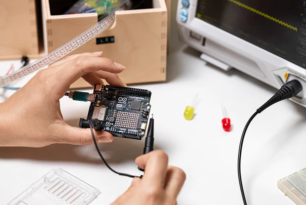 Arduino Uno R4 WiFi: Description, Features and applications
06 October 20235392
 SP2526A USB Power Distribution Switch: Pinout, Equivalent and Datasheet
15 March 2022500
 How to use BME280 with Arduino?
07 June 20223412
 MAN6760 Display Modules: Datasheet, Manufacturer, Application
02 November 20213545
 A Comprehensive Guide to LTC7841EUHE#PBF DC/DC Switching Controller
06 March 2024100
 What is Oscilloscope?
24 September 20217368
 What are the Types of Audio Cables?
27 October 20218680
 SR44 vs LR44 Which Battery Should You Use
21 August 20251417
 Introduction to Centrifugal Switch
27 January 202113137
 Understanding UARTs: The Basics and Benefits of Serial Communication
06 March 20232860
 Comparative Analysis of Si and SiC Devices for EV Traction Inverters
10 March 20235017
 China to Inject $40 Billion into Semiconductor Sector with New State Fund
07 September 20232690
 A Hybrid SiC and GaN-Based DC-DC Converter for EVs
20 September 20242405
Intel
In Stock
United States
China
Canada
Japan
Russia
Germany
United Kingdom
Singapore
Italy
Hong Kong(China)
Taiwan(China)
France
Korea
Mexico
Netherlands
Malaysia
Austria
Spain
Switzerland
Poland
Thailand
Vietnam
India
United Arab Emirates
Afghanistan
Åland Islands
Albania
Algeria
American Samoa
Andorra
Angola
Anguilla
Antigua & Barbuda
Argentina
Armenia
Aruba
Australia
Azerbaijan
Bahamas
Bahrain
Bangladesh
Barbados
Belarus
Belgium
Belize
Benin
Bermuda
Bhutan
Bolivia
Bonaire, Sint Eustatius and Saba
Bosnia & Herzegovina
Botswana
Brazil
British Indian Ocean Territory
British Virgin Islands
Brunei
Bulgaria
Burkina Faso
Burundi
Cabo Verde
Cambodia
Cameroon
Cayman Islands
Central African Republic
Chad
Chile
Christmas Island
Cocos (Keeling) Islands
Colombia
Comoros
Congo
Congo (DRC)
Cook Islands
Costa Rica
Côte d’Ivoire
Croatia
Cuba
Curaçao
Cyprus
Czechia
Denmark
Djibouti
Dominica
Dominican Republic
Ecuador
Egypt
El Salvador
Equatorial Guinea
Eritrea
Estonia
Eswatini
Ethiopia
Falkland Islands
Faroe Islands
Fiji
Finland
French Guiana
French Polynesia
Gabon
Gambia
Georgia
Ghana
Gibraltar
Greece
Greenland
Grenada
Guadeloupe
Guam
Guatemala
Guernsey
Guinea
Guinea-Bissau
Guyana
Haiti
Honduras
Hungary
Iceland
Indonesia
Iran
Iraq
Ireland
Isle of Man
Israel
Jamaica
Jersey
Jordan
Kazakhstan
Kenya
Kiribati
Kosovo
Kuwait
Kyrgyzstan
Laos
Latvia
Lebanon
Lesotho
Liberia
Libya
Liechtenstein
Lithuania
Luxembourg
Macao(China)
Madagascar
Malawi
Maldives
Mali
Malta
Marshall Islands
Martinique
Mauritania
Mauritius
Mayotte
Micronesia
Moldova
Monaco
Mongolia
Montenegro
Montserrat
Morocco
Mozambique
Myanmar
Namibia
Nauru
Nepal
New Caledonia
New Zealand
Nicaragua
Niger
Nigeria
Niue
Norfolk Island
North Korea
North Macedonia
Northern Mariana Islands
Norway
Oman
Pakistan
Palau
Palestinian Authority
Panama
Papua New Guinea
Paraguay
Peru
Philippines
Pitcairn Islands
Portugal
Puerto Rico
Qatar
Réunion
Romania
Rwanda
Samoa
San Marino
São Tomé & Príncipe
Saudi Arabia
Senegal
Serbia
Seychelles
Sierra Leone
Sint Maarten
Slovakia
Slovenia
Solomon Islands
Somalia
South Africa
South Sudan
Sri Lanka
St Helena, Ascension, Tristan da Cunha
St. Barthélemy
St. Kitts & Nevis
St. Lucia
St. Martin
St. Pierre & Miquelon
St. Vincent & Grenadines
Sudan
Suriname
Svalbard & Jan Mayen
Sweden
Syria
Tajikistan
Tanzania
Timor-Leste
Togo
Tokelau
Tonga
Trinidad & Tobago
Tunisia
Turkey
Turkmenistan
Turks & Caicos Islands
Tuvalu
U.S. Outlying Islands
U.S. Virgin Islands
Uganda
Ukraine
Uruguay
Uzbekistan
Vanuatu
Vatican City
Venezuela
Wallis & Futuna
Yemen
Zambia
Zimbabwe
![EPCS16SI8N]() EPCS16SI8N
EPCS16SI8NIntel
![EPCS4SI8N]() EPCS4SI8N
EPCS4SI8NIntel
![EPC2TI32N]() EPC2TI32N
EPC2TI32NIntel
![EPCS1SI8N]() EPCS1SI8N
EPCS1SI8NIntel
![EPCS64SI16N]() EPCS64SI16N
EPCS64SI16NIntel
![EPCQ64ASI16N]() EPCQ64ASI16N
EPCQ64ASI16NIntel
![EPC1441LC20]() EPC1441LC20
EPC1441LC20Intel
![EPC2LC20N]() EPC2LC20N
EPC2LC20NIntel
![EPC1LC20]() EPC1LC20
EPC1LC20Intel
![EPC1PI8N]() EPC1PI8N
EPC1PI8NIntel


