
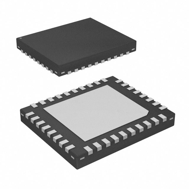
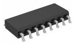
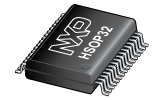
 Product
 Brand
Brand Articles
 Tools
Tools
How to use TMC2130 Motor Driver IC? [FAQ]


Motor Drivers
The TMC2130 is an integrated motor driver specifically meant for high voltage two-phase stepper motors with an SPI and STEP/DIR interface. This article will introduce TMC2130 systematically from its features, pinout to its specifications, applications, also including TMC2130 datasheet and so much more. Furthermore, Huge range of Semiconductors, Capacitors, Resistors and IcS in stock. Welcome RFQ.

Trinamic TMC2130 Stepper Motor Drivers with Ramps 1.4 (standalone mode)
- TMC2130 Pinout
- TMC2130 CAD Model
- TMC2130 Description
- TMC2130 Features
- Specifications
- TMC2130 Functional Block Diagram
- TMC2130 Standard Application Circuit
- TMC2130 Equivalent
- Other Motor Drivers
- How to use TMC2130 Motor Driver IC?
- Parts with Similar Specs
- TMC2130 Applications
- Using Warning
- TMC2130 Package
- TMC2130 Manufacturer
- Datasheet PDF
TMC2130 Pinout
The following figure is the diagram of TMC2130 Pinout.

Pinout
TMC2130 CAD Model
The followings are TMC2130 Symbol, Footprint, and 3D Model.

PCB Symbol

PCB Footprint

3D Model
TMC2130 Description
The TMC2130 is a high-performance driver integrated circuit for two-phase stepper motors. SPI and STEP/DIR standards make communication easier. TRINAMIC's innovative StealthChop chopper assures quiet operation while maximizing efficiency and motor power. CoolStep helps you to cut your energy use by up to 75%. DcStep drives big loads as quickly as feasible with minimizing step loss. Motor currents of up to 1.2A RMS (QFN package) / 1.4A RMS (TQFP package) or 2.5A short time peak current per coil are handled by integrated power MOSFETs. Protection and diagnostic functions help to ensure a stable and dependable functioning. The most advanced stepper motor driver in the industry allows for downsized designs with a low external component count for cost-effective and highly competitive solutions.
This article provides you with a basic overview of the TMC2130 Motor Driver IC, including its pin descriptions, features and specifications, etc., to help you quickly understand what TMC2130 is.
TMC2130 Features
● 2-phase stepper motors up to 2.0A coil current (2.5A peak)
● Step/Dir Interface with microstep interpolation MicroPlyer™
● SPI Interface
● Voltage Range 4.75V to 46V DC
● Highest Resolution 256 microsteps per full step
● StealthChop™ for extremely quiet operation and smooth motion
● spreadCycle™ highly dynamic motor control chopper
● DcStep™ load dependent speed control
● StallGuard2™ high precision sensorless motor load detection
● CoolStep™ current control for energy savings up to 75%
● Integrated Current Sense Option
● Passive Braking and freewheeling mode
● Full Protection & Diagnostics
● Small Size 5x6mm2 QFN36 package or TQFP48 package
Specifications
- TypeParameter
- Factory Lead Time6 Weeks
- Mount
In electronic components, the term "Mount" typically refers to the method or process of physically attaching or fixing a component onto a circuit board or other electronic device. This can involve soldering, adhesive bonding, or other techniques to secure the component in place. The mounting process is crucial for ensuring proper electrical connections and mechanical stability within the electronic system. Different components may have specific mounting requirements based on their size, shape, and function, and manufacturers provide guidelines for proper mounting procedures to ensure optimal performance and reliability of the electronic device.
Surface Mount - Mounting Type
The "Mounting Type" in electronic components refers to the method used to attach or connect a component to a circuit board or other substrate, such as through-hole, surface-mount, or panel mount.
Surface Mount - Package / Case
refers to the protective housing that encases an electronic component, providing mechanical support, electrical connections, and thermal management.
36-VFQFN Exposed Pad - Operating Temperature
The operating temperature is the range of ambient temperature within which a power supply, or any other electrical equipment, operate in. This ranges from a minimum operating temperature, to a peak or maximum operating temperature, outside which, the power supply may fail.
-40°C~125°C TJ - Packaging
Semiconductor package is a carrier / shell used to contain and cover one or more semiconductor components or integrated circuits. The material of the shell can be metal, plastic, glass or ceramic.
Tape & Reel (TR) - Published2016
- Part Status
Parts can have many statuses as they progress through the configuration, analysis, review, and approval stages.
Active - Moisture Sensitivity Level (MSL)
Moisture Sensitivity Level (MSL) is a standardized rating that indicates the susceptibility of electronic components, particularly semiconductors, to moisture-induced damage during storage and the soldering process, defining the allowable exposure time to ambient conditions before they require special handling or baking to prevent failures
3 (168 Hours) - Applications
The parameter "Applications" in electronic components refers to the specific uses or functions for which a component is designed. It encompasses various fields such as consumer electronics, industrial automation, telecommunications, automotive, and medical devices. Understanding the applications helps in selecting the right components for a particular design based on performance, reliability, and compatibility requirements. This parameter also guides manufacturers in targeting their products to relevant markets and customer needs.
General Purpose - Voltage - Supply
Voltage - Supply refers to the range of voltage levels that an electronic component or circuit is designed to operate with. It indicates the minimum and maximum supply voltage that can be applied for the device to function properly. Providing supply voltages outside this range can lead to malfunction, damage, or reduced performance. This parameter is critical for ensuring compatibility between different components in a circuit.
5.5V~46V - Function
The parameter "Function" in electronic components refers to the specific role or purpose that the component serves within an electronic circuit. It defines how the component interacts with other elements, influences the flow of electrical signals, and contributes to the overall behavior of the system. Functions can include amplification, signal processing, switching, filtering, and energy storage, among others. Understanding the function of each component is essential for designing effective and efficient electronic systems.
Driver - Fully Integrated, Control and Power Stage - Interface
In electronic components, the term "Interface" refers to the point at which two different systems, devices, or components connect and interact with each other. It can involve physical connections such as ports, connectors, or cables, as well as communication protocols and standards that facilitate the exchange of data or signals between the connected entities. The interface serves as a bridge that enables seamless communication and interoperability between different parts of a system or between different systems altogether. Designing a reliable and efficient interface is crucial in ensuring proper functionality and performance of electronic components and systems.
SPI, Step/Direction - Output Configuration
Output Configuration in electronic components refers to the arrangement or setup of the output pins or terminals of a device. It defines how the output signals are structured and how they interact with external circuits or devices. The output configuration can determine the functionality and compatibility of the component in a circuit design. Common types of output configurations include single-ended, differential, open-drain, and push-pull configurations, each serving different purposes and applications in electronic systems. Understanding the output configuration of a component is crucial for proper integration and operation within a circuit.
Half Bridge (4) - Logic Function
In electronic components, the term "Logic Function" refers to the specific operation or behavior of a component based on its input signals. It describes how the component processes the input signals to produce the desired output. Logic functions are fundamental to digital circuits and are used to perform logical operations such as AND, OR, NOT, and XOR.Each electronic component, such as logic gates or flip-flops, is designed to perform a specific logic function based on its internal circuitry. By understanding the logic function of a component, engineers can design and analyze complex digital systems to ensure proper functionality and performance. Different logic functions can be combined to create more complex operations, allowing for the creation of sophisticated digital devices and systems.
AND - Voltage - Load
Voltage - Load refers to the voltage across a load component in an electronic circuit when it is connected and operational. It represents the electrical potential difference that drives current through the load, which can be a resistor, motor, or other devices that consume electrical power. The voltage - load relationship is crucial for determining how much power the load will utilize and how it will affect the overall circuit performance. Properly managing voltage - load is essential for ensuring devices operate efficiently and safely within their specified limits.
5.5V~46V - Motor Type - Stepper
Motor Type - Stepper refers to a type of electromechanical device that converts electrical pulses into discrete mechanical movements. Stepper motors move in fixed angular increments or steps, allowing for precise control of position and speed. They are commonly used in applications requiring accurate positioning, such as 3D printers, CNC machines, and robotics. Stepper motors typically operate by energizing coils in a specific sequence, creating a magnetic field that moves the rotor in defined steps.
Bipolar - Step Resolution
Servo motor resolution is determined by feedback device of motor. I.e. 1000 PPR (pulses per revolution) quadrature encoder yields 1/4000 revolution resolution because 1000 PPR equals 4000 counts per revolution after standard 4X decoding.
1 ~ 1/256 - RoHS Status
RoHS means “Restriction of Certain Hazardous Substances” in the “Hazardous Substances Directive” in electrical and electronic equipment.
ROHS3 Compliant
TMC2130 Functional Block Diagram
The following is the Block Diagram of TMC2130.

Block Diagram
TMC2130 Standard Application Circuit
The following diagram shows the TMC2130 Standard Application Circuit.

Standard Application Circuit
TMC2130 Equivalent
TMC2100, TMC2208, TMC5160
Other Motor Drivers
DRV8825, L298, L293
How to use TMC2130 Motor Driver IC?
The TMC2130 is a 2-phase stepper motor driver that is capable of supplying up to 2A. It can communicate with an external microcontroller through an SPI and STEP/DIR interface.
It also integrates proprietary functions such as:
● stealthChop: a smoothing algorithm that makes movement and standstill inaudible
● spreadCycle: an algorithm for high dynamic motion and clean current waveform
● dcStep: load dependent speed control
● stallGuard2: sensorless stall detection and load measurement
● coolStep: load-dependent current consumption for high efficiency
● microPlyer: microstep interpolation to achieve smooth movement when using the STEP/DIR interface
The TMC2130 has three modes of operation:
1. STEP/DIR Driver Mode
An external microcontroller generates STEP and DIRECTION signals.
The STEP input is in the form of pulses that controls motor movement, and the DIR signal indicates the movement direction.
2. Standalone Mode
No external microcontroller is required and the movement is done using the STEP and DIR inputs. Configuration is done through the hardware pins.
3. SPI Driver Mode
Operation in this mode is combined with the TMC4361 IC to provide full control over the motor current.

Parts with Similar Specs
- ImagePart NumberManufacturerPackage / CaseLogic FunctionInterfaceMountPart StatusFactory Lead TimePbfree CodeMounting TypeView Compare
![TMC2130-LA-T]()
TMC2130-LA-T
36-VFQFN Exposed Pad
AND
SPI, Step/Direction
Surface Mount
Active
6 Weeks
-
Surface Mount
![NCV70514MW003R2G]()
16-WQFN Exposed Pad
AND
Parallel
Surface Mount
Active
6 Weeks
yes
Surface Mount
![DRV8801RTYR]()
16-WQFN Exposed Pad
AND
Parallel
Surface Mount
Active
6 Weeks
yes
Surface Mount
![TRF7970ARHBR]()
32-VFQFN Exposed Pad
AND
SPI
Surface Mount
Active
6 Weeks
yes
Surface Mount
![DRV8800RTYR]()
QFN
AND
SPI
Surface Mount
Active
22 Weeks
yes
-


TMC2130 Applications
● Textile, Sewing Machines
● Factory & Lab Automation
● 3D printers
● Liquid Handling
● Medical
● Office Automation
● CCTV, Security
● ATM, Cash recycler
● POS
● Pumps and Valves
Using Warning
Note: Please check their parameters and pin configuration before replacing them in your circuit.
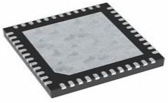
TMC2130 Package
The following diagrams show the TMC2130 Package.

Top View

Bottom View

Side View
TMC2130 Manufacturer
TRINAMIC Motion Control GmbH provides integrated circuits and modules for motor and motion control to customers all over the world, most of them leaders in their industry. TRINAMIC products are used in leading-edge industries such as biotechnology, lab automation, semiconductor handling equipment, CCTV, factory automation, and control all kinds of embedded motion control systems.
Headquartered in Hamburg, Germany with subsidiaries in Tallinn, Estonia, and Chicago, IL, USA, Trinamic provides integrated circuits, modules, and integrated mechatronics for embedded motor and motion control to customers all over the world.
Datasheet PDF
- Datasheets :
- Environmental Information :
How many pins of TMC2130-LA-T?
36 Pins.
What’s the operating temperature of TMC2130-LA-T?
-40°C~125°C TJ.
What are Trinamic drivers?
Stepper motors in a 3D printer are controlled by a variety of driver chips such as the common A4988 and DRV8825. These provide signals to the stepper motors to control the magnets and move them by micro-steps.
What are stepper motor drivers?
A Stepper Motor Driver is the driver circuit that enables the stepper motor to function the way it does. For example, stepper motors require sufficient and controlled energy for phases in a precise sequence. Due to this, stepper motors are considered more advanced than the typical DC motor.
How do I identify my stepper driver?
Consider voltage and current needs. A simple way to choose a stepper drive is to look for four things — voltage, current, microstepping, and maximum step pulse rate. Ensure that the drive can handle a wide range of current so that you can test the system at different voltage levels to fit your application.
What is a motor driver?
A motor driver takes the low-current signal from the controller circuit and amps it up into a high-current signal, to correctly drive the motor. It basically controls a high-current signal using a low-current signal. There are different types of motor drivers available in the market, in the form of ICs.
What is a silent stepper driver?
The SilentStepStick is a stepper driver board for 2-phase motors, based on the TMC2100, TMC2130, TMC2208, TMC2209 or TMC5160. The driver boards are compatible with StepSticks of the same familiar size and drop-in replacements for some of them.
 KSZ9031RNX Integrated Triple-speed Transceiver: Equivalent, Pinout and Datasheet
14 October 20213248
 MOC3052 Photocoupler: Datasheet, Alternatives and Pinout
16 August 20218059
 AT89S8253 Microcontroller: Pinout, Equivalent and Datasheet
25 February 20223577
 74HC75 Transparant Latch: Pinout, Equivalent and Datasheet
25 November 20214154
![CR14250SE Battery 3 V 1/2AA Lithium 850 mAh[Video]: Datasheet, Applications, and FAQ](https://res.utmel.com/Images/Article/3a17fd9e-1953-40ff-a82e-3a598316861d.jpg) CR14250SE Battery 3 V 1/2AA Lithium 850 mAh[Video]: Datasheet, Applications, and FAQ
CR14250SE Battery 3 V 1/2AA Lithium 850 mAh[Video]: Datasheet, Applications, and FAQ15 March 2022633
 PC123 Photocoupler: PC123 vs.PC817, Equivalents, Datasheet
08 October 202119225
 SG3525AP IC: Schematic, Applications and Datasheet
03 November 20232797
 Top Switch Detection Technologies Transforming Automotive Systems
07 June 2025198
 What is Surge?
09 February 20226641
 The Understanding to Autonomous Driving Sensor
10 November 20211326
 Stepper Motor: Types, Working and Applications
26 December 202510824
 What is an Application-specific Integrated Circuit?
13 April 20212250
 Chinese Chip Equipment Makers Thrive Amid US Restrictions
24 October 20232455
 Function and Application of Laser Sensors
28 October 20258216
 Metaverse Is Coming, Who Will Lead Us to Touch the Real Virtual World?
04 May 2022827
 Top 10 High-Performance End Mills for Metalworking in 2025
17 July 20254679
Trinamic Motion Control GmbH
In Stock: 38
Minimum: 1 Multiples: 1
Qty
Unit Price
Ext Price
1
$2.870796
$2.87
10
$2.708298
$27.08
100
$2.554999
$255.50
500
$2.410376
$1,205.19
1000
$2.273940
$2,273.94
Not the price you want? Send RFQ Now and we'll contact you ASAP.
Inquire for More Quantity
![TMC2660-PA]() TMC2660-PA
TMC2660-PATrinamic Motion Control GmbH
![TMC262-LA]() TMC262-LA
TMC262-LATrinamic Motion Control GmbH
![TMC2208-LA-T]() TMC2208-LA-T
TMC2208-LA-TTrinamic Motion Control GmbH
![TMC5160-TA]() TMC5160-TA
TMC5160-TATrinamic Motion Control GmbH
![TMC5130A-TA]() TMC5130A-TA
TMC5130A-TATrinamic Motion Control GmbH
![TMC260A-PA]() TMC260A-PA
TMC260A-PATrinamic Motion Control GmbH
![TMC261-PA]() TMC261-PA
TMC261-PATrinamic Motion Control GmbH
![TMC429-LI]() TMC429-LI
TMC429-LITrinamic Motion Control GmbH
![TMC236B-PA]() TMC236B-PA
TMC236B-PATrinamic Motion Control GmbH
![TMCM-343-H-CANOPEN]() TMCM-343-H-CANOPEN
TMCM-343-H-CANOPENTRINAMIC Motion Control GmbH


