

 Product
 Brand
Brand Articles
 Tools
Tools
1N4148W-7-F Switching Diode: Features, Pinout, and Datasheet

Standard Diode Rectifier Small Signal =< 200mA (Io), Any Speed 1.25V @ 150mA -65°C~150°C 1μA @ 75V 2-Termination Tape & Reel (TR) SOD-123 Surface Mount
Unit Price: $0.205788
Ext Price: $0.21


Standard Diode Rectifier Small Signal =< 200mA (Io), Any Speed 1.25V @ 150mA -65°C~150°C 1μA @ 75V 2-Termination Tape & Reel (TR) SOD-123 Surface Mount
The 1N4148W-7-F is a Surface Mount Fast Switching Diode. This article mainly introduces Features, Pinout, Datasheet and other detailed information about Diodes Incorporated 1N4148W-7-F.
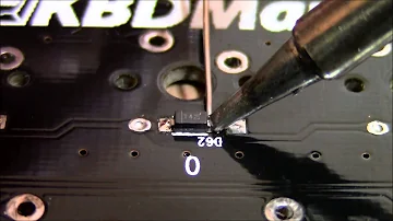
Soldering SMD diodes
1N4148W-7-F Description
1N4148W-7-F is a Diode Standard 100 V 300mA (DC) Surface Mount SOD-123.
1N4148W-7-F Pinout
The following shows 1N4148W-7-F Pinout.
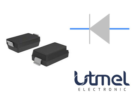
Pinout
1N4148W-7-F CAD Model
The followings are 1N4148W-7-F Symbol, Footprint and 3D Model.

Symbol

Footprint

3D Model
1N4148W-7-F Features
• Fast Switching Speed
• Low Forward Voltage: Maximum of 0.715V at 1mA
• Fast Reverse Recovery: Maximum of 4ns
• Low Capacitance: Maximum of 2pF
• Surface Mount Package Ideally Suited for Automated Insertion
• For General Purpose Switching Applications
• Totally Lead-Free & Fully RoHS Compliant
• Halogen and Antimony Free. “Green” Device
• Qualified to AEC-Q101 Standards for High Reliability
• PPAP Capable
Specifications
- TypeParameter
- Factory Lead Time17 Weeks
- Contact Plating
Contact plating (finish) provides corrosion protection for base metals and optimizes the mechanical and electrical properties of the contact interfaces.
Tin - Mount
In electronic components, the term "Mount" typically refers to the method or process of physically attaching or fixing a component onto a circuit board or other electronic device. This can involve soldering, adhesive bonding, or other techniques to secure the component in place. The mounting process is crucial for ensuring proper electrical connections and mechanical stability within the electronic system. Different components may have specific mounting requirements based on their size, shape, and function, and manufacturers provide guidelines for proper mounting procedures to ensure optimal performance and reliability of the electronic device.
Surface Mount - Mounting Type
The "Mounting Type" in electronic components refers to the method used to attach or connect a component to a circuit board or other substrate, such as through-hole, surface-mount, or panel mount.
Surface Mount - Package / Case
refers to the protective housing that encases an electronic component, providing mechanical support, electrical connections, and thermal management.
SOD-123 - Number of Pins2
- Weight10.007382mg
- Diode Element Material
The parameter "Diode Element Material" refers to the specific semiconductor material used in the construction of a diode. This material determines the electrical characteristics and performance of the diode, including its forward voltage drop, reverse breakdown voltage, and switching speed. Common diode element materials include silicon, germanium, and gallium arsenide, each offering different advantages for various applications. The choice of material impacts the diode's efficiency, thermal stability, and overall suitability for specific electronic circuits.
SILICON - Number of Elements1
- Packaging
Semiconductor package is a carrier / shell used to contain and cover one or more semiconductor components or integrated circuits. The material of the shell can be metal, plastic, glass or ceramic.
Tape & Reel (TR) - Published2012
- JESD-609 Code
The "JESD-609 Code" in electronic components refers to a standardized marking code that indicates the lead-free solder composition and finish of electronic components for compliance with environmental regulations.
e3 - Pbfree Code
The "Pbfree Code" parameter in electronic components refers to the code or marking used to indicate that the component is lead-free. Lead (Pb) is a toxic substance that has been widely used in electronic components for many years, but due to environmental concerns, there has been a shift towards lead-free alternatives. The Pbfree Code helps manufacturers and users easily identify components that do not contain lead, ensuring compliance with regulations and promoting environmentally friendly practices. It is important to pay attention to the Pbfree Code when selecting electronic components to ensure they meet the necessary requirements for lead-free applications.
yes - Part Status
Parts can have many statuses as they progress through the configuration, analysis, review, and approval stages.
Active - Moisture Sensitivity Level (MSL)
Moisture Sensitivity Level (MSL) is a standardized rating that indicates the susceptibility of electronic components, particularly semiconductors, to moisture-induced damage during storage and the soldering process, defining the allowable exposure time to ambient conditions before they require special handling or baking to prevent failures
1 (Unlimited) - Number of Terminations2
- ECCN Code
An ECCN (Export Control Classification Number) is an alphanumeric code used by the U.S. Bureau of Industry and Security to identify and categorize electronic components and other dual-use items that may require an export license based on their technical characteristics and potential for military use.
EAR99 - Max Operating Temperature
The Maximum Operating Temperature is the maximum body temperature at which the thermistor is designed to operate for extended periods of time with acceptable stability of its electrical characteristics.
150°C - Min Operating Temperature
The "Min Operating Temperature" parameter in electronic components refers to the lowest temperature at which the component is designed to operate effectively and reliably. This parameter is crucial for ensuring the proper functioning and longevity of the component, as operating below this temperature may lead to performance issues or even damage. Manufacturers specify the minimum operating temperature to provide guidance to users on the environmental conditions in which the component can safely operate. It is important to adhere to this parameter to prevent malfunctions and ensure the overall reliability of the electronic system.
-65°C - Additional Feature
Any Feature, including a modified Existing Feature, that is not an Existing Feature.
HIGH RELIABILITY - HTS Code
HTS (Harmonized Tariff Schedule) codes are product classification codes between 8-1 digits. The first six digits are an HS code, and the countries of import assign the subsequent digits to provide additional classification. U.S. HTS codes are 1 digits and are administered by the U.S. International Trade Commission.
8541.10.00.70 - Capacitance
Capacitance is a fundamental electrical property of electronic components that describes their ability to store electrical energy in the form of an electric field. It is measured in farads (F) and represents the ratio of the amount of electric charge stored on a component to the voltage across it. Capacitors are passive components that exhibit capacitance and are commonly used in electronic circuits for various purposes such as filtering, energy storage, timing, and coupling. Capacitance plays a crucial role in determining the behavior and performance of electronic systems by influencing factors like signal propagation, frequency response, and power consumption.
2pF - Power Rating
The "Power Rating" of an electronic component refers to the maximum amount of power that the component can handle or dissipate without being damaged. It is typically measured in watts and is an important specification to consider when designing or selecting components for a circuit. Exceeding the power rating of a component can lead to overheating, malfunction, or even permanent damage. It is crucial to ensure that the power rating of each component in a circuit is sufficient to handle the power levels expected during normal operation to maintain the reliability and longevity of the electronic system.
400mW - Voltage - Rated DC
Voltage - Rated DC is a parameter that specifies the maximum direct current (DC) voltage that an electronic component can safely handle without being damaged. This rating is crucial for ensuring the proper functioning and longevity of the component in a circuit. Exceeding the rated DC voltage can lead to overheating, breakdown, or even permanent damage to the component. It is important to carefully consider this parameter when designing or selecting components for a circuit to prevent any potential issues related to voltage overload.
75V - Terminal Position
In electronic components, the term "Terminal Position" refers to the physical location of the connection points on the component where external electrical connections can be made. These connection points, known as terminals, are typically used to attach wires, leads, or other components to the main body of the electronic component. The terminal position is important for ensuring proper connectivity and functionality of the component within a circuit. It is often specified in technical datasheets or component specifications to help designers and engineers understand how to properly integrate the component into their circuit designs.
DUAL - Terminal Form
Occurring at or forming the end of a series, succession, or the like; closing; concluding.
GULL WING - Peak Reflow Temperature (Cel)
Peak Reflow Temperature (Cel) is a parameter that specifies the maximum temperature at which an electronic component can be exposed during the reflow soldering process. Reflow soldering is a common method used to attach electronic components to a circuit board. The Peak Reflow Temperature is crucial because it ensures that the component is not damaged or degraded during the soldering process. Exceeding the specified Peak Reflow Temperature can lead to issues such as component failure, reduced performance, or even permanent damage to the component. It is important for manufacturers and assemblers to adhere to the recommended Peak Reflow Temperature to ensure the reliability and functionality of the electronic components.
260 - Current Rating
Current rating is the maximum current that a fuse will carry for an indefinite period without too much deterioration of the fuse element.
150mA - Time@Peak Reflow Temperature-Max (s)
Time@Peak Reflow Temperature-Max (s) refers to the maximum duration that an electronic component can be exposed to the peak reflow temperature during the soldering process, which is crucial for ensuring reliable solder joint formation without damaging the component.
40 - Base Part Number
The "Base Part Number" (BPN) in electronic components serves a similar purpose to the "Base Product Number." It refers to the primary identifier for a component that captures the essential characteristics shared by a group of similar components. The BPN provides a fundamental way to reference a family or series of components without specifying all the variations and specific details.
1N4148W - Pin Count
a count of all of the component leads (or pins)
2 - Voltage
Voltage is a measure of the electric potential difference between two points in an electrical circuit. It is typically represented by the symbol "V" and is measured in volts. Voltage is a crucial parameter in electronic components as it determines the flow of electric current through a circuit. It is responsible for driving the movement of electrons from one point to another, providing the energy needed for electronic devices to function properly. In summary, voltage is a fundamental concept in electronics that plays a key role in the operation and performance of electronic components.
100V - Element Configuration
The distribution of electrons of an atom or molecule (or other physical structure) in atomic or molecular orbitals.
Single - Speed
In electronic components, "Speed" typically refers to the rate at which data can be processed or transferred within the component. It is a measure of how quickly the component can perform its functions, such as executing instructions or transmitting signals. Speed is often specified in terms of frequency, such as clock speed in processors or data transfer rate in memory modules. Higher speed components can perform tasks more quickly, leading to improved overall performance in electronic devices. It is an important parameter to consider when designing or selecting electronic components for specific applications.
Small Signal =< 200mA (Io), Any Speed - Current
In electronic components, "Current" refers to the flow of electric charge through a conductor or semiconductor material. It is measured in amperes (A) and represents the rate at which electric charge is moving past a specific point in a circuit. Current is a crucial parameter in electronics as it determines the amount of power being consumed or delivered by a component. Understanding and controlling current is essential for designing and operating electronic circuits efficiently and safely. In summary, current is a fundamental electrical quantity that plays a key role in the functionality and performance of electronic components.
15A - Diode Type
In electronic components, the parameter "Diode Type" refers to the specific type or configuration of a diode, which is a semiconductor device that allows current to flow in one direction only. There are various types of diodes, each designed for specific applications and functions. Common diode types include rectifier diodes, zener diodes, light-emitting diodes (LEDs), and Schottky diodes, among others. The diode type determines the diode's characteristics, such as forward voltage drop, reverse breakdown voltage, and maximum current rating, making it crucial for selecting the right diode for a particular circuit or application. Understanding the diode type is essential for ensuring proper functionality and performance in electronic circuits.
Standard - Current - Reverse Leakage @ Vr
Current - Reverse Leakage @ Vr is a parameter that describes the amount of current that flows in the reverse direction through a diode or other semiconductor component when a reverse voltage (Vr) is applied across it. This leakage current is typically very small, but it is important to consider in electronic circuits as it can affect the overall performance and reliability of the component. The reverse leakage current is influenced by factors such as the material properties of the semiconductor, temperature, and the magnitude of the reverse voltage applied. Manufacturers provide this parameter in datasheets to help engineers and designers understand the behavior of the component in reverse bias conditions.
1μA @ 75V - Power Dissipation
the process by which an electronic or electrical device produces heat (energy loss or waste) as an undesirable derivative of its primary action.
400mW - Output Current
The rated output current is the maximum load current that a power supply can provide at a specified ambient temperature. A power supply can never provide more current that it's rated output current unless there is a fault, such as short circuit at the load.
150mA - Voltage - Forward (Vf) (Max) @ If
The parameter "Voltage - Forward (Vf) (Max) @ If" refers to the maximum voltage drop across a diode when it is forward-biased and conducting a specified forward current (If). It indicates the maximum potential difference the diode can withstand while allowing current to flow in the forward direction without breaking down. This value is crucial for designing circuits as it helps determine how much voltage will be lost across the diode during operation. Higher Vf values can lead to reduced efficiency in power applications, making this parameter essential for optimizing circuit performance.
1.25V @ 150mA - Forward Current
Current which flows upon application of forward voltage.
300mA - Operating Temperature - Junction
Operating Temperature - Junction refers to the maximum temperature at which the junction of an electronic component can safely operate without causing damage or performance degradation. This parameter is crucial for determining the reliability and longevity of the component, as excessive heat can lead to thermal stress and failure. Manufacturers specify the operating temperature range to ensure that the component functions within safe limits under normal operating conditions. It is important for designers and engineers to consider the operating temperature - junction when selecting and using electronic components to prevent overheating and ensure optimal performance.
-65°C~150°C - Max Surge Current
Surge current is a peak non repetitive current. Maximum (peak or surge) forward current = IFSM or if(surge), the maximum peak amount of current the diode is able to conduct in forward bias mode.
2A - Current - Average Rectified (Io)
The parameter "Current - Average Rectified (Io)" in electronic components refers to the average value of the rectified current flowing through the component. This parameter is important in determining the average power dissipation and thermal considerations of the component. It is typically specified in datasheets for diodes, rectifiers, and other components that handle alternating current (AC) and convert it to direct current (DC). Understanding the average rectified current helps in selecting the appropriate component for a given application to ensure reliable operation and prevent overheating.
300mA DC - Forward Voltage
the amount of voltage needed to get current to flow across a diode.
1.25V - Max Reverse Voltage (DC)
Max Reverse Voltage (DC) refers to the maximum voltage that a semiconductor device, such as a diode, can withstand in the reverse bias direction without failing. Exceeding this voltage can lead to breakdown and potential damage to the component. It is a critical parameter in circuit design to ensure reliability and prevent failure when the device is subjected to reverse voltage conditions.
100V - Average Rectified Current
Mainly used to characterize alternating voltage and current. It can be computed by averaging the absolute value of a waveform over one full period of the waveform.
300mA - Reverse Recovery Time
Reverse Recovery Time is a key parameter in semiconductor devices, particularly diodes and transistors. It refers to the time taken for a diode or transistor to switch from conducting in the forward direction to blocking in the reverse direction when the polarity of the voltage across the device is reversed. This parameter is crucial in applications where fast switching speeds are required, as a shorter reverse recovery time allows for quicker response times and improved efficiency. Reverse Recovery Time is typically specified in datasheets for electronic components and is an important consideration in circuit design to ensure optimal performance and reliability.
4 ns - Peak Reverse Current
The maximum voltage that a diode can withstand in the reverse direction without breaking down or avalanching.If this voltage is exceeded the diode may be destroyed. Diodes must have a peak inverse voltage rating that is higher than the maximum voltage that will be applied to them in a given application.
1μA - Max Repetitive Reverse Voltage (Vrrm)
The Max Repetitive Reverse Voltage (Vrrm) is a crucial parameter in electronic components, particularly in diodes and transistors. It refers to the maximum voltage that can be applied across the component in the reverse direction without causing damage. This parameter is important for ensuring the proper functioning and longevity of the component in circuits where reverse voltage may be present. Exceeding the Vrrm rating can lead to breakdown and failure of the component, so it is essential to carefully consider this specification when designing or selecting components for a circuit.
100V - Capacitance @ Vr, F
Capacitance @ Vr, F refers to the capacitance value of a capacitor measured at a specified rated voltage (Vr). It indicates how much electrical charge the capacitor can store per volt when subjected to this voltage. This parameter is essential for understanding the behavior of capacitors in circuits, particularly under different voltage conditions, and ensures that the component operates within its safe limits. The unit of measurement is Farads (F), which quantifies the capacitor's ability to hold an electrical charge.
2pF @ 0V 1MHz - Peak Non-Repetitive Surge Current
Peak Non-Repetitive Surge Current is a specification in electronic components that refers to the maximum current that the component can withstand for a short duration without sustaining damage. This surge current typically occurs as a result of sudden voltage spikes or transient events in the circuit. It is important to consider this parameter when designing or selecting components to ensure they can handle occasional high-current surges without failing. The value of Peak Non-Repetitive Surge Current is usually specified in amperes and is crucial for protecting the component and maintaining the overall reliability of the circuit.
2A - Max Forward Surge Current (Ifsm)
Max Forward Surge Current (Ifsm) is a parameter used to specify the maximum peak current that a diode or other electronic component can withstand for a short duration during a surge event. Surge currents can occur due to sudden changes in voltage or power supply fluctuations, and the Ifsm rating helps determine the component's ability to handle such transient overloads without being damaged. It is important to consider the Ifsm rating when selecting components for applications where surge currents are expected, such as in power supplies, motor drives, and other high-power circuits. Exceeding the Ifsm rating can lead to overheating, degradation, or failure of the component, so it is crucial to ensure that the chosen component can safely handle the expected surge currents in the circuit.
2A - Recovery Time
Recovery time in electronic components refers to the time it takes for a device to return to its normal operating state after being subjected to a specific stimulus or disturbance. This parameter is particularly important in devices such as diodes, transistors, and capacitors, where the recovery time can impact the overall performance and reliability of the component. A shorter recovery time indicates that the component can quickly recover from a transient event, ensuring proper functionality and minimizing any potential disruptions in the circuit. Manufacturers typically provide recovery time specifications to help engineers and designers select components that meet the requirements of their specific applications.
4 ns - Height1.25mm
- Length2.85mm
- Width1.7mm
- REACH SVHC
The parameter "REACH SVHC" in electronic components refers to the compliance with the Registration, Evaluation, Authorization, and Restriction of Chemicals (REACH) regulation regarding Substances of Very High Concern (SVHC). SVHCs are substances that may have serious effects on human health or the environment, and their use is regulated under REACH to ensure their safe handling and minimize their impact.Manufacturers of electronic components need to declare if their products contain any SVHCs above a certain threshold concentration and provide information on the safe use of these substances. This information allows customers to make informed decisions about the potential risks associated with using the components and take appropriate measures to mitigate any hazards.Ensuring compliance with REACH SVHC requirements is essential for electronics manufacturers to meet regulatory standards, protect human health and the environment, and maintain transparency in their supply chain. It also demonstrates a commitment to sustainability and responsible manufacturing practices in the electronics industry.
No SVHC - Radiation Hardening
Radiation hardening is the process of making electronic components and circuits resistant to damage or malfunction caused by high levels of ionizing radiation, especially for environments in outer space (especially beyond the low Earth orbit), around nuclear reactors and particle accelerators, or during nuclear accidents or nuclear warfare.
No - RoHS Status
RoHS means “Restriction of Certain Hazardous Substances” in the “Hazardous Substances Directive” in electrical and electronic equipment.
ROHS3 Compliant - Lead Free
Lead Free is a term used to describe electronic components that do not contain lead as part of their composition. Lead is a toxic material that can have harmful effects on human health and the environment, so the electronics industry has been moving towards lead-free components to reduce these risks. Lead-free components are typically made using alternative materials such as silver, copper, and tin. Manufacturers must comply with regulations such as the Restriction of Hazardous Substances (RoHS) directive to ensure that their products are lead-free and environmentally friendly.
Lead Free
Parts with Similar Specs
- ImagePart NumberManufacturerMountPackage / CaseForward VoltageAverage Rectified CurrentCurrent - Average Rectified (Io)Reverse Recovery TimeRecovery TimeMoisture Sensitivity Level (MSL)View Compare
![1N4148W-7-F]()
1N4148W-7-F
Surface Mount
SOD-123
1.25 V
300 mA
300mA (DC)
4 ns
4 ns
1 (Unlimited)
![BAV99-7-F]()
Surface Mount
TO-236-3, SC-59, SOT-23-3
1.25 V
300 mA
300mA (DC)
4 ns
4 ns
1 (Unlimited)
![BAW56-7-F]()
Surface Mount
TO-236-3, SC-59, SOT-23-3
1.25 V
300 mA
300mA (DC)
4 ns
4 ns
1 (Unlimited)
![MMBD7000-7-F]()
Surface Mount
TO-236-3, SC-59, SOT-23-3
1.25 V
300 mA
300mA (DC)
4 ns
4 ns
1 (Unlimited)


1N4148W-7-F Marking Information
The 1N4148W-7-F Marking Information is shown as follows.
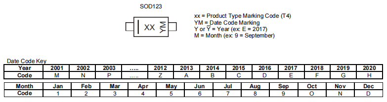
Marking Information
1N4148W-7-F Circuit
The following shows 1N4148W-7-F Circuit.
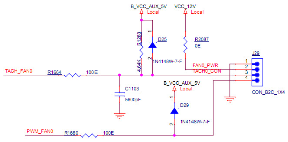
Circuit
1N4148W-7-F Layout
The 1N4148W-7-F Layout is given below.
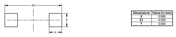
Layout
1N4148W-7-F Package
The 1N4148W-7-F Package is shown as follows.
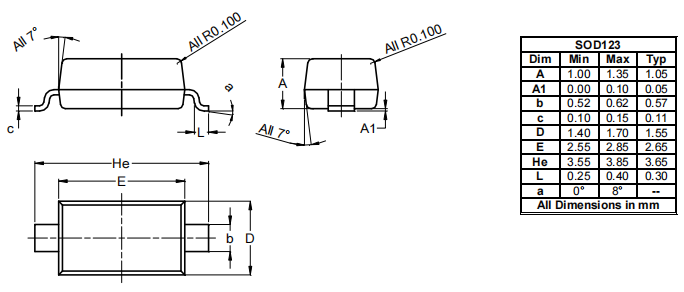
Package
1N4148W-7-F Manufacturer
Diodes Incorporated manufactures high-quality semiconductors for the consumer electronics, computing, communications, industrial, and automotive industries. To suit clients' needs, they use their enlarged product line of discrete, analog, and mixed-signal components, as well as cutting-edge packaging technologies. We can be a premier provider for high-volume, high-growth markets because of our comprehensive range of application-specific solutions and solutions-focused sales, as well as our global operations of 25 facilities, which include engineering, testing, production, and customer service.
Trend Analysis
Datasheet PDF
- Environmental Information :
- PCN Assembly/Origin :
- PCN Design/Specification :
- Datasheets :
Which diode has the fastest switching?
Schottky diodes are significantly faster since they are unipolar devices and their speed is only limited by the junction capacitance. The switching time is ~100 ps for the small-signal diodes, and up to tens of nanoseconds for special high-capacity power diodes.
What is a switching diode?
A switching diode is suitable for switching a small signal of up to 100 mA, acting as a rectifier. In contrast, a rectifier diode is used for AC line rectification (from alternating current to direct current). Switching diodes are designed to handle a voltage of less than tens of volts.
 TXB0108PWR Translator:Features, Applications and Datasheet
23 October 20231149
![NE555 VS TLC555[Video] Comparison the differences between them.](https://res.utmel.com/Images/Article/cfe1f243-e88e-4d21-a827-80df4dfc394f.png) NE555 VS TLC555[Video] Comparison the differences between them.
NE555 VS TLC555[Video] Comparison the differences between them.25 April 202210227
 NE555 Precision Timer: Features, Specifications and Applications
11 May 20211712
 CD4081 Quad 2 Input AND Gate IC: Pinout, Datasheet and Circuit
28 October 202111650
 GRM155R71C104KA88D Murata Electronics SMD 0402 125°C T/R: Datasheet, Features, and Equivalents
18 February 20221388
 2N5551 Transistor: Pinout, Datasheet, and Applications
09 July 202114509
![RP2040 VS ATMEGA328 VS ESP32 VS STM32[Video]: Comparison some parameters of Microcontrollers](https://res.utmel.com/Images/Article/2556d243-de71-4c53-82cd-f80372b12c36.jpg) RP2040 VS ATMEGA328 VS ESP32 VS STM32[Video]: Comparison some parameters of Microcontrollers
RP2040 VS ATMEGA328 VS ESP32 VS STM32[Video]: Comparison some parameters of Microcontrollers23 September 202324977
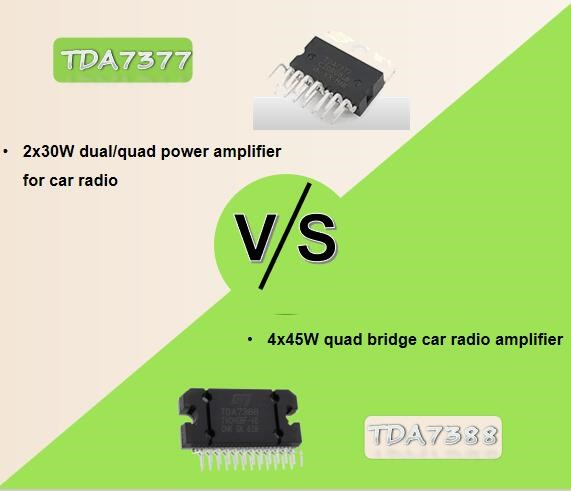 TDA7377 Amplifier vs TDA7388 Amplifier
05 November 202418725
 Why does a MOSFET with a Small Internal Resistance Heat Up?
09 May 20223954
 50 Frequently Asked Questions about Oscilloscope
22 November 202113531
 Challenges and Control Approaches for Current Sharing in DC Microgrids
07 June 20235278
 The Rise of Co-Packaged Optics (CPO) and Silicon Photonics in AI Superclusters
24 June 20262612
 5 Easy Ways to Choose Sample-and-Hold Amplifiers
06 June 20253593
 AI Server MLCCs: Why NVIDIA Rubin Racks Require Over 600,000 Capacitors
02 June 20262759
 What is a USB Type-C Connector?
28 October 20256692
 SoftBank's Arm Gears Up for the Largest IPO of 2023 Riding the AI Wave
07 September 20233689
Diodes Incorporated
In Stock: 6300
Minimum: 1 Multiples: 1
Qty
Unit Price
Ext Price
1
$0.205788
$0.21
10
$0.194140
$1.94
100
$0.183151
$18.32
500
$0.172784
$86.39
1000
$0.163004
$163.00
Not the price you want? Send RFQ Now and we'll contact you ASAP.
Inquire for More Quantity
![BAV16W-7-F]() BAV16W-7-F
BAV16W-7-FDiodes Incorporated
![B340A-13-F]() B340A-13-F
B340A-13-FDiodes Incorporated
![BAT42W-7-F]() BAT42W-7-F
BAT42W-7-FDiodes Incorporated
![MMBD4148-7-F]() MMBD4148-7-F
MMBD4148-7-FDiodes Incorporated
![BAT43WS-7-F]() BAT43WS-7-F
BAT43WS-7-FDiodes Incorporated
![BAT54WS-7-F]() BAT54WS-7-F
BAT54WS-7-FDiodes Incorporated
![BAT42WS-7-F]() BAT42WS-7-F
BAT42WS-7-FDiodes Incorporated
![1N5819HW-7-F]() 1N5819HW-7-F
1N5819HW-7-FDiodes Incorporated
![1N4148WT-7]() 1N4148WT-7
1N4148WT-7Diodes Incorporated


