
 Product
 Brand
Brand Articles
 Tools
Tools
LM7912 Negative Regulators: Diagram, Pinout and Datasheet


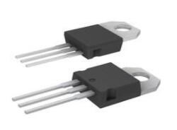
Fixed 2.54mm LM7912 PMIC 3 TO-220-3
LM7912 is a 3-terminal negative regulators. This article mainly introduce its diagram, pinout, datasheet and other detailed information about Texas Instruments LM7912.

Fix fix fix LM7912
LM7912 Description
LM7912 is a three-terminal negative 12 volts voltage regulator IC,used for regulating negative voltages.
It consists of three pins and has a fixed output voltage of -12V. Most of the applications need both positive and negative voltages for their operation.
The negative voltages should be stable otherwise they can damage the circuit or reduce the life of components used in the circuit. Therefore, negative voltage regulators sever this application purpose.
LM7912 Pinout

LM7912 CAD Model
Symbol

Footprint

3D Model

LM7912 Features
• Thermal, short circuit and safe area protection
• High ripple rejection
• Output current: 1.5A
• Peak output current:2.2A
• The output voltage tolerance is ± 4%.
• fixed output voltage:-12V
• Average output current: up to 1A
• Package: TO-220 only
• The input voltage should lie in between -27V to -14.5V
• Safe area protection is provided for output transistors.
• It has a high power supply rejection ratio and low noise.
• It has a low quiescent current which ensures good regulation.
• 12V Negative voltage regulator
Specifications
- TypeParameter
- Lifecycle Status
Lifecycle Status refers to the current stage of an electronic component in its product life cycle, indicating whether it is active, obsolete, or transitioning between these states. An active status means the component is in production and available for purchase. An obsolete status indicates that the component is no longer being manufactured or supported, and manufacturers typically provide a limited time frame for support. Understanding the lifecycle status is crucial for design engineers to ensure continuity and reliability in their projects.
NRND (Last Updated: 1 day ago) - Mount
In electronic components, the term "Mount" typically refers to the method or process of physically attaching or fixing a component onto a circuit board or other electronic device. This can involve soldering, adhesive bonding, or other techniques to secure the component in place. The mounting process is crucial for ensuring proper electrical connections and mechanical stability within the electronic system. Different components may have specific mounting requirements based on their size, shape, and function, and manufacturers provide guidelines for proper mounting procedures to ensure optimal performance and reliability of the electronic device.
Through Hole - Mounting Type
The "Mounting Type" in electronic components refers to the method used to attach or connect a component to a circuit board or other substrate, such as through-hole, surface-mount, or panel mount.
Through Hole - Package / Case
refers to the protective housing that encases an electronic component, providing mechanical support, electrical connections, and thermal management.
TO-220-3 - Number of Pins3
- Operating Temperature
The operating temperature is the range of ambient temperature within which a power supply, or any other electrical equipment, operate in. This ranges from a minimum operating temperature, to a peak or maximum operating temperature, outside which, the power supply may fail.
0°C~125°C - Packaging
Semiconductor package is a carrier / shell used to contain and cover one or more semiconductor components or integrated circuits. The material of the shell can be metal, plastic, glass or ceramic.
Tube - JESD-609 Code
The "JESD-609 Code" in electronic components refers to a standardized marking code that indicates the lead-free solder composition and finish of electronic components for compliance with environmental regulations.
e0 - Part Status
Parts can have many statuses as they progress through the configuration, analysis, review, and approval stages.
Not For New Designs - Moisture Sensitivity Level (MSL)
Moisture Sensitivity Level (MSL) is a standardized rating that indicates the susceptibility of electronic components, particularly semiconductors, to moisture-induced damage during storage and the soldering process, defining the allowable exposure time to ambient conditions before they require special handling or baking to prevent failures
1 (Unlimited) - Number of Terminations3
- ECCN Code
An ECCN (Export Control Classification Number) is an alphanumeric code used by the U.S. Bureau of Industry and Security to identify and categorize electronic components and other dual-use items that may require an export license based on their technical characteristics and potential for military use.
EAR99 - Terminal Finish
Terminal Finish refers to the surface treatment applied to the terminals or leads of electronic components to enhance their performance and longevity. It can improve solderability, corrosion resistance, and overall reliability of the connection in electronic assemblies. Common finishes include nickel, gold, and tin, each possessing distinct properties suitable for various applications. The choice of terminal finish can significantly impact the durability and effectiveness of electronic devices.
Tin/Lead (Sn/Pb) - Max Power Dissipation
The maximum power that the MOSFET can dissipate continuously under the specified thermal conditions.
15W - Terminal Position
In electronic components, the term "Terminal Position" refers to the physical location of the connection points on the component where external electrical connections can be made. These connection points, known as terminals, are typically used to attach wires, leads, or other components to the main body of the electronic component. The terminal position is important for ensuring proper connectivity and functionality of the component within a circuit. It is often specified in technical datasheets or component specifications to help designers and engineers understand how to properly integrate the component into their circuit designs.
SINGLE - Number of Functions1
- Terminal Pitch
The center distance from one pole to the next.
2.54mm - Current Rating
Current rating is the maximum current that a fuse will carry for an indefinite period without too much deterioration of the fuse element.
1.5A - Base Part Number
The "Base Part Number" (BPN) in electronic components serves a similar purpose to the "Base Product Number." It refers to the primary identifier for a component that captures the essential characteristics shared by a group of similar components. The BPN provides a fundamental way to reference a family or series of components without specifying all the variations and specific details.
LM7912 - Pin Count
a count of all of the component leads (or pins)
3 - Number of Outputs1
- Voltage - Input (Max)
Voltage - Input (Max) is a parameter in electronic components that specifies the maximum voltage that can be safely applied to the input of the component without causing damage. This parameter is crucial for ensuring the proper functioning and longevity of the component. Exceeding the maximum input voltage can lead to electrical overstress, which may result in permanent damage or failure of the component. It is important to carefully adhere to the specified maximum input voltage to prevent any potential issues and maintain the reliability of the electronic system.
-35V - Output Voltage
Output voltage is a crucial parameter in electronic components that refers to the voltage level produced by the component as a result of its operation. It represents the electrical potential difference between the output terminal of the component and a reference point, typically ground. The output voltage is a key factor in determining the performance and functionality of the component, as it dictates the level of voltage that will be delivered to the connected circuit or load. It is often specified in datasheets and technical specifications to ensure compatibility and proper functioning within a given system.
-12V - Output Type
The "Output Type" parameter in electronic components refers to the type of signal or data that is produced by the component as an output. This parameter specifies the nature of the output signal, such as analog or digital, and can also include details about the voltage levels, current levels, frequency, and other characteristics of the output signal. Understanding the output type of a component is crucial for ensuring compatibility with other components in a circuit or system, as well as for determining how the output signal can be utilized or processed further. In summary, the output type parameter provides essential information about the nature of the signal that is generated by the electronic component as its output.
Fixed - Max Output Current
The maximum current that can be supplied to the load.
1.5A - Output Configuration
Output Configuration in electronic components refers to the arrangement or setup of the output pins or terminals of a device. It defines how the output signals are structured and how they interact with external circuits or devices. The output configuration can determine the functionality and compatibility of the component in a circuit design. Common types of output configurations include single-ended, differential, open-drain, and push-pull configurations, each serving different purposes and applications in electronic systems. Understanding the output configuration of a component is crucial for proper integration and operation within a circuit.
Negative - Quiescent Current
The quiescent current is defined as the current level in the amplifier when it is producing an output of zero.
3mA - Accuracy
Accuracy in electronic components refers to the degree to which a measured value agrees with the true or accepted value. It evaluates the precision of a component in providing correct output or measurement under specified conditions. High accuracy indicates minimal deviation from the actual value, while low accuracy shows significant error in measurement. This parameter is crucial in applications where precise data is essential for reliable performance and decision-making.
4 % - Output Voltage 1
Output Voltage 1 is a parameter commonly found in electronic components such as voltage regulators, power supplies, and amplifiers. It refers to the voltage level that is produced or delivered by the component at a specific output terminal or pin. This parameter is crucial for determining the performance and functionality of the component in a circuit. The specified output voltage should meet the requirements of the connected devices or components to ensure proper operation and compatibility. It is important to carefully consider and verify the output voltage 1 specification when selecting and using electronic components in a design or application.
12V - Number of Regulators
A regulator is a mechanism or device that controls something such as pressure, temperature, or fluid flow. The voltage regulator keeps the power level stabilized. A regulator is a mechanism or device that controls something such as pressure, temperature, or fluid flow.
1 - Min Input Voltage
The parameter "Min Input Voltage" in electronic components refers to the minimum voltage level that must be applied to the component for it to operate within its specified parameters. This value is crucial as providing a voltage below this minimum threshold may result in the component malfunctioning or not functioning at all. It is important to adhere to the specified minimum input voltage to ensure the proper operation and longevity of the electronic component. Failure to meet this requirement may lead to potential damage to the component or the overall system in which it is used.
-14.5V - Protection Features
Protection features in electronic components refer to the built-in mechanisms or functionalities designed to safeguard the component and the overall system from various external factors or internal faults. These features are crucial for ensuring the reliability, longevity, and safety of the electronic device. Common protection features include overvoltage protection, overcurrent protection, reverse polarity protection, thermal protection, and short-circuit protection. By activating these features when necessary, the electronic component can prevent damage, malfunctions, or hazards that may arise from abnormal operating conditions or unforeseen events. Overall, protection features play a vital role in enhancing the robustness and resilience of electronic components in diverse applications.
Over Temperature, Short Circuit - Current - Quiescent (Iq)
The parameter "Current - Quiescent (Iq)" in electronic components refers to the amount of current consumed by a device when it is in a quiescent or idle state, meaning when it is not actively performing any tasks or operations. This parameter is important because it represents the baseline power consumption of the device even when it is not actively being used. A lower quiescent current (Iq) value is desirable as it indicates that the device is more energy-efficient and will consume less power when not in use, which can help extend battery life in portable devices and reduce overall power consumption in electronic systems. Designers often pay close attention to the quiescent current specification when selecting components for low-power applications or battery-operated devices.
1.5mA - Voltage Dropout (Max)
Voltage Dropout (Max) refers to the minimum voltage difference between the input and output of a voltage regulator or linear power supply needed to maintain proper regulation. It indicates the maximum allowable voltage drop across the device for it to function effectively without dropout. If the input voltage falls below this threshold, the output voltage may drop below the specified level, leading to potential operational issues for connected components. This parameter is critical for ensuring stable and reliable power delivery in electronic circuits.
1.1V @ 1A - PSRR
PSRR stands for Power Supply Rejection Ratio. It is a measure of how well a device, such as an amplifier or a voltage regulator, can reject variations in the power supply voltage. A high PSRR value indicates that the device is able to maintain its performance even when the power supply voltage fluctuates. This parameter is important in ensuring stable and reliable operation of electronic components, especially in applications where the power supply voltage may not be perfectly regulated. A good PSRR helps to minimize noise and interference in the output signal of the device.
70dB (120Hz) - Dropout Voltage
Dropout voltage is the input-to-output differential voltage at which the circuit ceases to regulate against further reductions in input voltage; this point occurs when the input voltage approaches the output voltage.
1.1V - Dropout Voltage1-Nom
Dropout Voltage1-Nom is a parameter commonly found in voltage regulators and power management ICs. It refers to the minimum voltage difference required between the input voltage and the output voltage for the regulator to maintain regulation. In other words, it is the minimum voltage drop that the regulator can handle while still providing a stable output voltage. This parameter is important to consider when designing power supply circuits to ensure that the regulator can operate within its specified voltage range and maintain proper regulation under varying load conditions.
1.1V - Power Supply Rejection Ratio (PSRR)
Power Supply Rejection Ratio (PSRR) is a measure of how well an electronic component, such as an operational amplifier or voltage regulator, can reject changes in its supply voltage. It indicates the ability of the component to maintain a stable output voltage despite fluctuations in the input supply voltage. A higher PSRR value signifies better performance in rejecting noise and variations from the power supply, leading to improved signal integrity and more reliable operation in electronic circuits. PSRR is typically expressed in decibels (dB).
70dB - Voltage Tolerance-Max
Voltage Tolerance-Max is a parameter in electronic components that specifies the maximum allowable deviation from the rated voltage without causing damage or malfunction. It indicates the range within which the component can safely operate without being affected by voltage fluctuations. This parameter is crucial for ensuring the reliability and longevity of the component in various electrical systems. Manufacturers provide this specification to help users understand the limits within which the component can function properly and to prevent potential failures due to overvoltage conditions.
5% - Nominal Output Voltage
Nominal Output Voltage refers to the specified or intended voltage level that an electronic component or device is designed to provide as output under normal operating conditions. It is a crucial parameter that indicates the expected voltage level that the component will deliver to the connected circuit or load. This value is typically specified by the manufacturer and is important for ensuring proper functionality and compatibility within a system. It is important to note that the actual output voltage may vary slightly due to factors such as load variations, temperature changes, and other environmental conditions.
-12V - Output Voltage Accuracy
Output voltage accuracy is a crucial parameter in electronic components, especially in devices like voltage regulators and power supplies. It refers to how closely the actual output voltage matches the specified or desired voltage level. This parameter is typically expressed as a percentage of the nominal output voltage. A higher accuracy value indicates that the output voltage is more consistent and reliable, which is important for ensuring proper functioning of electronic circuits and devices. Manufacturers often provide specifications for output voltage accuracy to help users select components that meet their requirements for precision and performance.
4 % - Height4.7mm
- Length14.986mm
- Width10.16mm
- Thickness
Thickness in electronic components refers to the measurement of how thick a particular material or layer is within the component structure. It can pertain to various aspects, such as the thickness of a substrate, a dielectric layer, or conductive traces. This parameter is crucial as it impacts the electrical, mechanical, and thermal properties of the component, influencing its performance and reliability in electronic circuits.
4.572mm - REACH SVHC
The parameter "REACH SVHC" in electronic components refers to the compliance with the Registration, Evaluation, Authorization, and Restriction of Chemicals (REACH) regulation regarding Substances of Very High Concern (SVHC). SVHCs are substances that may have serious effects on human health or the environment, and their use is regulated under REACH to ensure their safe handling and minimize their impact.Manufacturers of electronic components need to declare if their products contain any SVHCs above a certain threshold concentration and provide information on the safe use of these substances. This information allows customers to make informed decisions about the potential risks associated with using the components and take appropriate measures to mitigate any hazards.Ensuring compliance with REACH SVHC requirements is essential for electronics manufacturers to meet regulatory standards, protect human health and the environment, and maintain transparency in their supply chain. It also demonstrates a commitment to sustainability and responsible manufacturing practices in the electronics industry.
No SVHC - Radiation Hardening
Radiation hardening is the process of making electronic components and circuits resistant to damage or malfunction caused by high levels of ionizing radiation, especially for environments in outer space (especially beyond the low Earth orbit), around nuclear reactors and particle accelerators, or during nuclear accidents or nuclear warfare.
No - RoHS Status
RoHS means “Restriction of Certain Hazardous Substances” in the “Hazardous Substances Directive” in electrical and electronic equipment.
Non-RoHS Compliant
LM7912 Schematic Diagram

−5V

−12V and −15V
LM7912 Internal Block Diagram

Where to use LM7912?
LM7912 belongs to the family of Voltage regulators. The name “79” indicates negative and the term “12” indicates the voltage. So “7912” means that this IC will regulate a negative 12V for your projects. You can also check on 78 series for positive voltage regulators.
When you are designing an analog circuit, the circuit might need negative voltage either as a power source or as a reference voltage. In both cases LM7912 will be an ideal choice when you need a negative 12V. The output current of this IC is upto 1A, however with appropriate heat sink the datasheet says that a peak current of 2.2A can be achieved through this IC.
How to use LM7912?
The LM7912 is a -12V Voltage regulator IC. Meaning it will provide a constant output voltage of -12V when the input voltage is between -14.5V to -27V. A very basic Voltage regulator circuit is shown below.

I have used a Battery to power the IC, but you can use any power source but notice that the supply voltage should be negative. Hence, I have interchanged the polarity of the battery. The Input and output capacitors C1 (10uF) and C2 (1uF) are used to filter noise from the input and the output voltage respectively. The negative output voltage is obtained from the Vo (3rd Pin) which is also read using a Multimeter. The value of the capacitors need not be the exact values, you can use the closest value you have got.
There are many other ways in which the IC can be used based on your application. The circuit diagram for those can be found at the datasheet given at the end of this page.
LM7912 Applications
●Use as power or reference voltage for analog and digital circuits.
●Current Limiter for certain applications
●Dual regulated supply.
●This IC can design a current limiter in various applications.
●High-sensitivity light controllers
●It also has a protection circuit for output polarity-reversal.
●LM7912 has a dual supply.
●High stability 1A regulator.
●As a current source.
●Light Controller using silicon photocell.
●Dual trimmed supply.
LM7912 Mechanical Data

LM7912 Manufacturer
Texas Instruments Incorporated (TI) is an American technology company headquartered in Dallas, Texas, that designs and manufactures semiconductors and various integrated circuits, which it sells to electronics designers and manufacturers globally.[6] It is one of the top 10 semiconductor companies worldwide based on sales volume.The company's focus is on developing analog chips and embedded processors, which account for more than 80% of its revenue.TI also produces TI digital light processing technology and education technology products including calculators, microcontrollers and multi-core processors. The company holds 45,000 patents worldwide as of 2016.
Trend Analysis
Datasheet PDF
- Datasheets :
- PCN Assembly/Origin :
1.What is the function of each pin of LM7912?
Face yourself with the pin on the bottom and the round hole on the top. The left, middle and right thirds have 123 pins respectively.
Pins 1 and 2 are the voltage input terminals, 1 is connected to the positive power supply, and 2 is grounded. Pin 2, 3 is the voltage output terminal, 3 is connected to the power output, and 2 is grounded. LM7912, the input terminal can be connected to 12-14VDC, and the output is -12VDC
2.How to connect LM7912 in multisim?
One input, one output, and one connect ground.
3.I want to ask if LM7812 and LM7912 can use the same heat sink?
It cannot be shared because the 7812 heat sink is the ground terminal, and the 7912 heat sink is the negative power input terminal. If the heat sink is shared without insulation measures, it is equivalent to a short circuit to the ground at the negative power input terminal. Of course insurance is burned.
If you really need to share the heat sink, you must attach the 7912 heat sink to the heat sink after adding an insulating thermal pad, and also add an insulating washer to the fixing screw.
![CR1216 3 V Battery Non-Rechargeable[Video]: Datasheet, CR1216 VS CR2016, and Equivalents](https://res.utmel.com/Images/Article/0b54a9ba-2bd8-4e1e-993a-827e6c746ece.png) CR1216 3 V Battery Non-Rechargeable[Video]: Datasheet, CR1216 VS CR2016, and Equivalents
CR1216 3 V Battery Non-Rechargeable[Video]: Datasheet, CR1216 VS CR2016, and Equivalents01 April 20224147
![LM3524 Regulating Pulse Width Modulator: Pinout, LM3524 vs. SG3524 [Video]](https://res.utmel.com/Images/Article/e463ae26-8c33-42d9-b1a4-5d493bc8cf87.jpg) LM3524 Regulating Pulse Width Modulator: Pinout, LM3524 vs. SG3524 [Video]
LM3524 Regulating Pulse Width Modulator: Pinout, LM3524 vs. SG3524 [Video]22 December 20223160
 A Comprehensive Guide to LTC6993CDCB-3#TRMPBF Multivibrator IC
06 March 2024300
 TL074CN: 3MHz,Solder temperature, Pinout and Datasheet
21 February 20223879
 CS124 SSR RELAY SPST-NO 3.5A 0-40V: Datasheet, Features and Equivalents
11 January 2022329
 BU406 Transistor: Equivalent, Datasheet and Pinout
15 November 202115832
 MJ15003 NPN Transistor: Datasheet, Pinout, and Equivalent
05 November 20219488
 BC556B Transistor: TO-92 PNP Transistor, Datasheet and Equivalents
25 March 20224315
 Introduction to Wireless Sensor Networks
20 August 20204788
 How to Decide Which Relay Socket Is Right for Your Next Build
10 July 20252831
 Electronic Components Distributor Utmel to Showcase at 2024 IPC APEX EXPO
10 April 20245860
 Samsung: 3nm Yield Rate of 20%
19 April 20225263
 Automotive Chips Rose Across the Board!
11 March 20223630
 Understanding of Carbon Film Resistors
17 October 202524944
 Characteristics and Working Principle of IGBT
31 October 202522903
 Metaverse Is Coming, Who Will Lead Us to Touch the Real Virtual World?
04 May 2022819
Texas Instruments
In Stock: 18
Minimum: 1 Multiples: 1
Qty
Unit Price
Ext Price
1
$1.648787
$1.65
10
$1.555459
$15.55
100
$1.467415
$146.74
500
$1.384353
$692.18
1000
$1.305994
$1,305.99
Not the price you want? Send RFQ Now and we'll contact you ASAP.
Inquire for More Quantity
![TPS767D301PWPR]() TPS767D301PWPR
TPS767D301PWPRTexas Instruments
![LP2988AIMM-3.3]() LP2988AIMM-3.3
LP2988AIMM-3.3Texas Instruments
![LMS1587CSX-ADJ]() LMS1587CSX-ADJ
LMS1587CSX-ADJTexas Instruments
![LP3962ESX-2.5]() LP3962ESX-2.5
LP3962ESX-2.5Texas Instruments
![LP2967ITPX-1833/NOPB]() LP2967ITPX-1833/NOPB
LP2967ITPX-1833/NOPBTexas Instruments
![LP2951CMX/NOPB]() LP2951CMX/NOPB
LP2951CMX/NOPBTexas Instruments
![LM1117MPX-3.3/NOPB]() LM1117MPX-3.3/NOPB
LM1117MPX-3.3/NOPBTexas Instruments
![LP2985IM5-3.3/NOPB]() LP2985IM5-3.3/NOPB
LP2985IM5-3.3/NOPBTexas Instruments
![LM2937IMP-5.0/NOPB]() LM2937IMP-5.0/NOPB
LM2937IMP-5.0/NOPBTexas Instruments
![LP2951ACMM/NOPB]() LP2951ACMM/NOPB
LP2951ACMM/NOPBTexas Instruments


