
 Product
 Brand
Brand Articles
 Tools
Tools
MCP2515 CAN Controller: Datasheet, Pinout, Block Diagram

2.7V~5.5V CAN 2.0 SPI Controllers Interface ICs QUAD MCP2515 20 Pins Controller 0.5mm 20-VFQFN Exposed Pad
Unit Price: $4.038542
Ext Price: $4.04


2.7V~5.5V CAN 2.0 SPI Controllers Interface ICs QUAD MCP2515 20 Pins Controller 0.5mm 20-VFQFN Exposed Pad
This article will unlock more details about Microchip Technology’s MCP2515, a stand-alone Controller Area Network (CAN) controller.

Arduino MCP2515 CAN Bus Interface Tutorial
MCP2515 Pinout

MCP2515 Pinout
| Pin | Pin Name | Description |
| 19 | TXCAN | Transmit output pin to CAN bus |
| 20 | RXCAN | Receive input pin from CAN bus |
| 1 | CLKOUT | Clock output pin with programmable Prescaler |
| 2 | TXORTS | Transmit buffer TXB0 Request- to-Send; 100 kQ internal pul-up to VDD |
| 3 | TX1RTS | Transmit buffer TXB1 Request-to Send; 100 k22 internal pull-ups to VDD |
| 5 | TX2RTS | Transmit buffer TXB2 Request-to Send; 100 k2 internal pull-ups to VDD |
| 6 | OSC2 | Oscillator output |
| 7 | OSC1 | Oscillator input |
| 8 | Vss | Ground reference for logic and I/0 pins |
| 9 | RX1BF | Receive buffer RXB1 interrupt pin or general-purpose digital output |
| 10 | RX0BF | Receive buffer RXB0 interrupt pin or general-purpose digital output |
| 11 | NT | Interrupt output pin |
| 12 | SCK | Clock input pin for SPI interface |
| 14 | SI | Data input pin for SPI interface |
| 15 | SO | Data output pin for SPI interface |
| 16 | CS | Chip select input pin for SPI interface |
| 17 | RESET | Active-low device Reset input |
| 18 | VDD | Positive supply for logic and /0 pins |
| 4,13 | NC | No intemal connection |
| 21 | EP | Exposed Thermal Pad, connect to Vss. |
Pin Description
MCP2515 CAD Model
Symbol

MCP2515 Symbol
Footprint

MCP2515 Footprint
3D Model

MCP2515 3D Model
MCP2515 Description
Microchip Technology MCP2515 is a stand-alone Controller Area Network (CAN) controller that implements the CAN specification, Version 2.0B. It is capable of transmitting and receiving both standard and extended data and remote frames. The MCP2515 has two acceptance masks and six acceptance filters that are used to filter out unwanted messages, thereby reducing the host MCU’s overhead. The MCP2515 interfaces with microcontrollers (MCUs) via an industry-standard Serial Peripheral Interface (SPI).
Specifications
- TypeParameter
- Factory Lead Time6 Weeks
- Mount
In electronic components, the term "Mount" typically refers to the method or process of physically attaching or fixing a component onto a circuit board or other electronic device. This can involve soldering, adhesive bonding, or other techniques to secure the component in place. The mounting process is crucial for ensuring proper electrical connections and mechanical stability within the electronic system. Different components may have specific mounting requirements based on their size, shape, and function, and manufacturers provide guidelines for proper mounting procedures to ensure optimal performance and reliability of the electronic device.
Surface Mount - Package / Case
refers to the protective housing that encases an electronic component, providing mechanical support, electrical connections, and thermal management.
20-VFQFN Exposed Pad - Number of Pins20
- Operating Temperature
The operating temperature is the range of ambient temperature within which a power supply, or any other electrical equipment, operate in. This ranges from a minimum operating temperature, to a peak or maximum operating temperature, outside which, the power supply may fail.
-40°C~125°C - Packaging
Semiconductor package is a carrier / shell used to contain and cover one or more semiconductor components or integrated circuits. The material of the shell can be metal, plastic, glass or ceramic.
Tube - Published2007
- JESD-609 Code
The "JESD-609 Code" in electronic components refers to a standardized marking code that indicates the lead-free solder composition and finish of electronic components for compliance with environmental regulations.
e3 - Pbfree Code
The "Pbfree Code" parameter in electronic components refers to the code or marking used to indicate that the component is lead-free. Lead (Pb) is a toxic substance that has been widely used in electronic components for many years, but due to environmental concerns, there has been a shift towards lead-free alternatives. The Pbfree Code helps manufacturers and users easily identify components that do not contain lead, ensuring compliance with regulations and promoting environmentally friendly practices. It is important to pay attention to the Pbfree Code when selecting electronic components to ensure they meet the necessary requirements for lead-free applications.
yes - Part Status
Parts can have many statuses as they progress through the configuration, analysis, review, and approval stages.
Active - Moisture Sensitivity Level (MSL)
Moisture Sensitivity Level (MSL) is a standardized rating that indicates the susceptibility of electronic components, particularly semiconductors, to moisture-induced damage during storage and the soldering process, defining the allowable exposure time to ambient conditions before they require special handling or baking to prevent failures
1 (Unlimited) - Number of Terminations20
- Terminal Finish
Terminal Finish refers to the surface treatment applied to the terminals or leads of electronic components to enhance their performance and longevity. It can improve solderability, corrosion resistance, and overall reliability of the connection in electronic assemblies. Common finishes include nickel, gold, and tin, each possessing distinct properties suitable for various applications. The choice of terminal finish can significantly impact the durability and effectiveness of electronic devices.
Matte Tin (Sn) - annealed - Voltage - Supply
Voltage - Supply refers to the range of voltage levels that an electronic component or circuit is designed to operate with. It indicates the minimum and maximum supply voltage that can be applied for the device to function properly. Providing supply voltages outside this range can lead to malfunction, damage, or reduced performance. This parameter is critical for ensuring compatibility between different components in a circuit.
2.7V~5.5V - Terminal Position
In electronic components, the term "Terminal Position" refers to the physical location of the connection points on the component where external electrical connections can be made. These connection points, known as terminals, are typically used to attach wires, leads, or other components to the main body of the electronic component. The terminal position is important for ensuring proper connectivity and functionality of the component within a circuit. It is often specified in technical datasheets or component specifications to help designers and engineers understand how to properly integrate the component into their circuit designs.
QUAD - Terminal Form
Occurring at or forming the end of a series, succession, or the like; closing; concluding.
NO LEAD - Peak Reflow Temperature (Cel)
Peak Reflow Temperature (Cel) is a parameter that specifies the maximum temperature at which an electronic component can be exposed during the reflow soldering process. Reflow soldering is a common method used to attach electronic components to a circuit board. The Peak Reflow Temperature is crucial because it ensures that the component is not damaged or degraded during the soldering process. Exceeding the specified Peak Reflow Temperature can lead to issues such as component failure, reduced performance, or even permanent damage to the component. It is important for manufacturers and assemblers to adhere to the recommended Peak Reflow Temperature to ensure the reliability and functionality of the electronic components.
260 - Supply Voltage
Supply voltage refers to the electrical potential difference provided to an electronic component or circuit. It is crucial for the proper operation of devices, as it powers their functions and determines performance characteristics. The supply voltage must be within specified limits to ensure reliability and prevent damage to components. Different electronic devices have specific supply voltage requirements, which can vary widely depending on their design and intended application.
5V - Terminal Pitch
The center distance from one pole to the next.
0.5mm - Time@Peak Reflow Temperature-Max (s)
Time@Peak Reflow Temperature-Max (s) refers to the maximum duration that an electronic component can be exposed to the peak reflow temperature during the soldering process, which is crucial for ensuring reliable solder joint formation without damaging the component.
40 - Base Part Number
The "Base Part Number" (BPN) in electronic components serves a similar purpose to the "Base Product Number." It refers to the primary identifier for a component that captures the essential characteristics shared by a group of similar components. The BPN provides a fundamental way to reference a family or series of components without specifying all the variations and specific details.
MCP2515 - Function
The parameter "Function" in electronic components refers to the specific role or purpose that the component serves within an electronic circuit. It defines how the component interacts with other elements, influences the flow of electrical signals, and contributes to the overall behavior of the system. Functions can include amplification, signal processing, switching, filtering, and energy storage, among others. Understanding the function of each component is essential for designing effective and efficient electronic systems.
Controller - Qualification Status
An indicator of formal certification of qualifications.
Not Qualified - Interface
In electronic components, the term "Interface" refers to the point at which two different systems, devices, or components connect and interact with each other. It can involve physical connections such as ports, connectors, or cables, as well as communication protocols and standards that facilitate the exchange of data or signals between the connected entities. The interface serves as a bridge that enables seamless communication and interoperability between different parts of a system or between different systems altogether. Designing a reliable and efficient interface is crucial in ensuring proper functionality and performance of electronic components and systems.
SPI - Operating Supply Current
Operating Supply Current, also known as supply current or quiescent current, is a crucial parameter in electronic components that indicates the amount of current required for the device to operate under normal conditions. It represents the current drawn by the component from the power supply while it is functioning. This parameter is important for determining the power consumption of the component and is typically specified in datasheets to help designers calculate the overall power requirements of their circuits. Understanding the operating supply current is essential for ensuring proper functionality and efficiency of electronic systems.
10mA - Max Supply Current
Max Supply Current refers to the maximum amount of electrical current that a component can draw from its power supply under normal operating conditions. It is a critical parameter that ensures the component operates reliably without exceeding its thermal limits or damaging internal circuitry. Exceeding this current can lead to overheating, performance degradation, or failure of the component. Understanding this parameter is essential for designing circuits that provide adequate power while avoiding overload situations.
10mA - Clock Frequency
Clock frequency, also known as clock speed, refers to the rate at which a processor or electronic component can execute instructions. It is measured in hertz (Hz) and represents the number of cycles per second that the component can perform. A higher clock frequency typically indicates a faster processing speed and better performance. However, it is important to note that other factors such as architecture, efficiency, and workload also play a significant role in determining the overall performance of a component. In summary, clock frequency is a crucial parameter that influences the speed and efficiency of electronic components in processing data and executing tasks.
40MHz - Protocol
In electronic components, the parameter "Protocol" refers to a set of rules and standards that govern the communication between devices. It defines the format, timing, sequencing, and error checking methods for data exchange between different components or systems. Protocols ensure that devices can understand and interpret data correctly, enabling them to communicate effectively with each other. Common examples of protocols in electronics include USB, Ethernet, SPI, I2C, and Bluetooth, each with its own specifications for data transmission. Understanding and adhering to protocols is essential for ensuring compatibility and reliable communication between electronic devices.
CANbus - Boundary Scan
Boundary scan is a testing technique used in electronic components to verify the interconnections between integrated circuits on a printed circuit board. It allows for the testing of digital circuits by providing a way to shift data in and out of devices through a serial interface. This method helps in identifying faults such as short circuits, open circuits, and incorrect connections without the need for physical access to the individual components. Boundary scan is commonly used during manufacturing, testing, and debugging processes to ensure the quality and reliability of electronic products.
NO - Low Power Mode
Low Power Mode is a feature found in electronic components, such as microcontrollers, processors, and devices, that allows them to operate at reduced power consumption levels. When activated, the component typically reduces its clock speed, voltage, or disables certain functions to conserve energy. This mode is often used to extend battery life in portable devices or reduce overall power consumption in energy-efficient systems. Low Power Mode can be triggered automatically based on certain conditions, such as low battery levels, or manually by the user or software. It is a crucial feature in modern electronics to balance performance with energy efficiency.
YES - Number of Transceivers1
- Number of Serial I/Os1
- Standards
The parameter "Standards" in electronic components refers to established criteria or specifications that ensure interoperability, safety, and performance across various electronic devices and systems. These standards are often set by recognized organizations and describe the characteristics, dimensions, and testing methods for components. Adherence to these standards helps manufacturers produce compatible and reliable products, facilitates communication between devices, and ensures compliance with regulatory requirements. Standards play a crucial role in the consistency and quality of electronic components in the industry.
CAN 2.0 - Data Encoding/Decoding Method
Data Encoding/Decoding Method in electronic components refers to the process of converting data from one format to another for transmission or storage purposes. This method involves encoding the data into a specific format before transmission and decoding it back to its original form upon reception. The encoding process typically involves converting the data into a series of bits or symbols that can be easily transmitted over a communication channel. Common encoding methods include techniques such as Manchester encoding, NRZ (Non-Return-to-Zero) encoding, and differential encoding. Decoding, on the other hand, involves reversing the encoding process to retrieve the original data from the received signals. The choice of data encoding/decoding method can impact factors such as data transmission speed, error detection, and compatibility with different communication protocols.
NRZ - Number of Receive Buffers2
- Number of Transmit Buffers3
- Height950μm
- Length4mm
- Width4mm
- REACH SVHC
The parameter "REACH SVHC" in electronic components refers to the compliance with the Registration, Evaluation, Authorization, and Restriction of Chemicals (REACH) regulation regarding Substances of Very High Concern (SVHC). SVHCs are substances that may have serious effects on human health or the environment, and their use is regulated under REACH to ensure their safe handling and minimize their impact.Manufacturers of electronic components need to declare if their products contain any SVHCs above a certain threshold concentration and provide information on the safe use of these substances. This information allows customers to make informed decisions about the potential risks associated with using the components and take appropriate measures to mitigate any hazards.Ensuring compliance with REACH SVHC requirements is essential for electronics manufacturers to meet regulatory standards, protect human health and the environment, and maintain transparency in their supply chain. It also demonstrates a commitment to sustainability and responsible manufacturing practices in the electronics industry.
No SVHC - RoHS Status
RoHS means “Restriction of Certain Hazardous Substances” in the “Hazardous Substances Directive” in electrical and electronic equipment.
ROHS3 Compliant
Parts with Similar Specs
- ImagePart NumberManufacturerPackage / CaseNumber of PinsInterfaceSupply VoltageTechnologyMountRoHS StatusNumber of TerminationsView Compare
![MCP2515-E/ML]()
MCP2515-E/ML
20-VFQFN Exposed Pad
20
SPI
5 V
CMOS
Surface Mount
ROHS3 Compliant
20
![ATTINY2313-20MU]()
20-WFQFN Exposed Pad
20
SPI, UART, USART
5 V
CMOS
Surface Mount
ROHS3 Compliant
20
![ST7FLI15BF1U6TR]()
20-VQFN Exposed Pad
20
-
5 V
CMOS
Surface Mount
ROHS3 Compliant
20
![MCP2515T-I/ML]()
20-VFQFN Exposed Pad
20
SPI
-
CMOS
Surface Mount
ROHS3 Compliant
20
![MCP2515-I/ML]()
20-VFQFN Exposed Pad
20
SPI
-
CMOS
Surface Mount
ROHS3 Compliant
20


MCP2515 Features
• Implements CAN V2.0B at 1 Mb/s:
- 0 to 8-byte length in the data field
- Standard and extended data and remote frames
• Receive Buffers, Masks and Filters:
- Two receive buffers with prioritized message storage
- Six 29-bit filters
- Two 29-bit masks
• Data Byte Filtering on the First Two Data Bytes (applies to standard data frames)
• Three Transmit Buffers with Prioritization and Abort Features
• High-Speed SPI Interface (10 MHz):
- SPI modes 0,0 and 1,1
• One-Shot mode Ensures Message Transmission is Attempted Only One Time
• Clock Out Pin with Programmable Prescaler:
- Can be used as a clock source for other device(s)
• Start-of-Frame (SOF) Signal is Available for Monitoring the SOF Signal:
- Can be used for time slot-based protocols and/or bus diagnostics to detect early bus degradation
• Interrupt Output Pin with Selectable Enables
• Buffer Full Output Pins Configurable as:
- Interrupt output for each receive buffer
- General-purpose output
• Request-to-Send (RTS) Input Pins Individually
Configurable as:
- Control pins to request transmission for each transmit buffer
- General-purpose inputs
• Low-Power CMOS Technology:
- Operates from 2.7V-5.5V
- 5 mA active current (typical)
- 1 μA standby current (typical) (Sleep mode)
• Temperature Ranges Supported:
- Industrial (I): -40°C to +85°C
- Extended (E): -40°C to +125°C
MCP2515 Block Diagram
The MCP2515 is a stand-alone CAN controller developed to simplify applications that require interfacing with a CAN bus. A simple block diagram of the MCP2515 is shown below.

MCP2515 Block Diagram
The device consists of three main blocks:
1. The CAN module, which includes the CAN protocol engine, masks, filters, transmit and receive buffers.
2. The control logic and registers that are used to configure the device and its operation.
3. The SPI protocol block.
An example system implementation using the device is shown below.

MCP2515 Example System Impementation
MCP2515 Mode of Operation
The MCP2515 has five modes of operation. These modes are:
1. Configuration mode
2. Normal mode
3. Sleep mode
4. Listen-Only mode
5. Loopback mode
MCP2515 Package

MCP2515 Package
MCP2515 Manufacturer
Microchip Technology Incorporated is a leading provider of smart, connected and secure embedded control solutions. Its easy-to-use development tools and comprehensive product portfolio enable customers to create optimal designs, which reduce risk while lowering total system cost and time to market. The company's solutions serve more than 120,000 customers across the industrial, automotive, consumer, aerospace and defence, communications and computing markets. Headquartered in Chandler, Arizona, Microchip offers outstanding technical support along with dependable delivery and quality.
Datasheet PDF
- Datasheets :
- PCN Design/Specification :
- PCN Packaging :
- ConflictMineralStatement :
Popularity by Region
How do I connect an MCP2515 to Arduino?
In this illustration we will go to wire the MCP2515 CAN-BUS Breakout Module, MCP2515 is a standalone controller area network or CAN manufactured by Microchip semiconductor, that implements the CAN specification version 2.0B it is capable of transmitting and receiving both standard and extended data remote frames.
How do I get started with an MCP2515 CAN-BUS module?
The CAN-BUS Shield provides your Arduino or Redboard with CAN-BUS capabilities and allows you to hack your vehicle. This shield allows you to poll the ECU for information including coolant temperature, throttle position, vehicle speed, and engine RPMs. You can also store this data or output it to a screen to make an in-dash project.
How do I connect an MCP2515 to a Raspberry Pi?
This post walks through setting up a CAN controller on the Raspberry Pi. My goal is to help demystify the process and provide simple instructions that a relative beginner should be able to follow. Particularly, including information that I wish was more readily available when I started with the project.
Where can I find a MCP2515 schematic?
These Arduino CAN-Bus modules are based on the MCP2515 CAN Controller and the TJA1050 CAN Transceiver. They provide a lot of bang for the buck and will allow you start to start interfacing your projects with CAN networks. Common CAN applications include vehicles (via OBDII or J1939) and industrial monitoring and controls.
 OPA548 Operational Amplifiers: Pinout, Application and Datasheet PDF
03 July 20215699
 AD8367 500 MHz Variable Gain Amplifier: Datasheet, Pinout, and AGC Design Analysis
17 March 2026346
 A Comprehensive Guide to LTC699IS8#TRPBF - Simple Reset/Power-On Reset Supervisor
06 March 2024229
 rj11 vs rj45: What’s the difference?
30 March 20225020
 FSUSB42MUX Switch: Features, Applications and Datasheet
13 December 20232389
 LMV324 - Rail-to-Rail Operational Amplifier
07 December 20214246
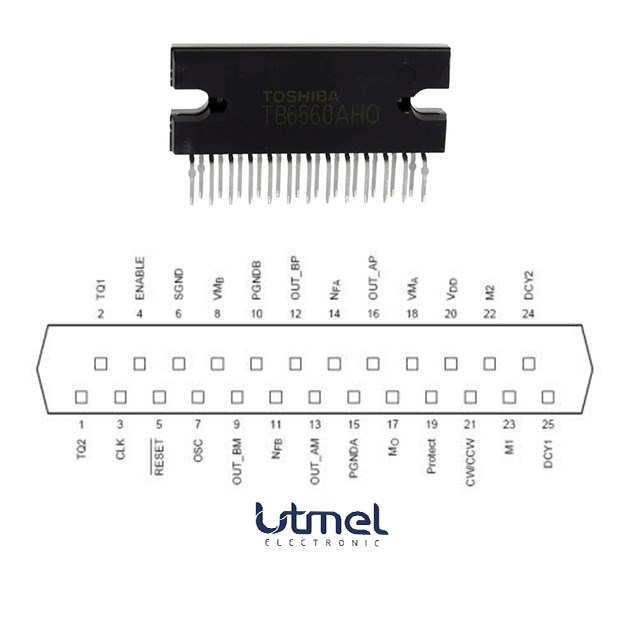 TB6560AHQ:PWM chopper-type stepping motor driver IC
17 April 20251733
 W25Q16JVSSIQ IC: Features, Applications and Datasheet
16 November 20231115
 Semiconductor Industry Techniques Revolutionize Battery Manufacturing
06 November 20232388
 What is a Microcontroller?
30 October 2025117738
 Domestic SSD Master Chip Maker, Achieving a New Breakthrough in PCIe 5.0
27 April 2022705
 How are Integrated Circuits produced?
20 October 202526228
 ARM, FPGA, DSP and CPLD: Connection and Difference
15 March 20228403
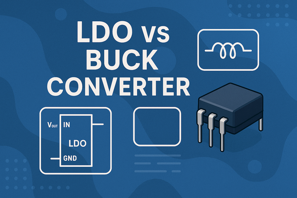 LDO vs Buck Converter: Which Power Regulator Is Best For Your Application?
16 May 20257605
 Kyoto University Successfully Demonstrates That SiC Can Also Work at 350°C
26 March 2022752
 What is a Fixed Inductor?
15 April 202113189
Microchip Technology
In Stock: 5089
Minimum: 1 Multiples: 1
Qty
Unit Price
Ext Price
1
$4.038542
$4.04
10
$3.809945
$38.10
100
$3.594288
$359.43
500
$3.390838
$1,695.42
1000
$3.198904
$3,198.90
Not the price you want? Send RFQ Now and we'll contact you ASAP.
Inquire for More Quantity
![KSZ8895MQXIA]() KSZ8895MQXIA
KSZ8895MQXIAMicrochip Technology
![USB2514BI-AEZG]() USB2514BI-AEZG
USB2514BI-AEZGMicrochip Technology
![USB2514B-AEZC-TR]() USB2514B-AEZC-TR
USB2514B-AEZC-TRMicrochip Technology
![MCP2515-I/ST]() MCP2515-I/ST
MCP2515-I/STMicrochip Technology
![MCP2515-I/SO]() MCP2515-I/SO
MCP2515-I/SOMicrochip Technology
![ENC28J60-I/SS]() ENC28J60-I/SS
ENC28J60-I/SSMicrochip Technology
![KSZ8873MMLI]() KSZ8873MMLI
KSZ8873MMLIMicrochip Technology
![MCP2200-I/SO]() MCP2200-I/SO
MCP2200-I/SOMicrochip Technology
![KSZ8863RLLI]() KSZ8863RLLI
KSZ8863RLLIMicrochip Technology
![KSZ8863MLL]() KSZ8863MLL
KSZ8863MLLMicrochip Technology


